
Abstract
Advances in laboratory instrumentation often increase the complexity, size, and cost of the device. The resulting complexity and cost, however, then reduce the accessibility of the device to many laboratories. We examine ways to use technological advances to simplify the design of laboratory devices, retaining the essential components that yield sufficient capabilities for routine uses. Inverted fluorescence microscopes, for example, have evolved into large complex instruments with exquisite imaging capability and are loaded with features requiring trained users and costing tens of thousands of dollars. This has limited their potential ubiquity within laboratories. For simple fluorescence microscopy applications, a much smaller and less expensive device with far fewer features would minimize the issues encountered with traditional inverted fluorescence microscopes. Advances in inexpensive complimentary metal-oxide semiconductor sensor technology have allowed its consideration as an alternative to the expensive charge-coupled device cameras currently used. Based on these advances, we have developed a compact, single-color, single-magnification device with a retail price an order of magnitude lower than current benchtop fluorescence microscopes. This device makes routine fluorescence microscopy applications immediately accessible to individual researchers and less well-funded laboratories. Tasks such as determining the presence of cells, their health, confluence, and fluorescent labeling or protein expression are compatible with such a simplified version. The low cost, small size, and ease of use of this device allows fluorescence microscopy to become more accessible for point-of-care medicine and at many points in the research process.
Introduction
Technology very often drives advances in scientific and medical research instrumentation. This often results in increasingly complex, large, and expensive devices, as layer after layer of features are built into the device. The cost, size, and complexity then limit the accessibility of the device to laboratories that are well funded, have the required space, and the personnel trained in their operation and maintenance. 1 It is possible for the evolution of instrumental analysis to lead to smaller, cheaper, and easier-to-use devices for those applications with a potential market size that can support the development costs. 2 The cellular telephone changed when and how we communicate by phone and is an excellent example of how increased access opens new markets. 3 Similarly, the miniaturization of blood glucose monitors allowed the development of portable, personal, affordable versions of these devices accessible to virtually every diabetic patient. 4 5 More recently, the development of an ultrasound imaging system based on a personal digital assistant has widened the accessibility of this diagnostic procedure to a significant degree. 6
A fundamental tool of biologists in general and cell biologists in particular is the microscope. Ever since Robert Hooke 7 in England saw the cells of a cork sample under his compound microscope, a prime mode of biological research has been simply observation of the minute. Antoni van Leeuwenhoek in the Netherlands developed his own single lens monocular microscope in 1674 to become the discoverer of single-celled animals, bacteria and protozoa. In the 400 years since the first compound microscope was built (around 1595), the underlying design of microscopes has changed very little: light travels from a source, through the sample, through tubes and lenses, to the eye. Lenses and mirrors bend light, and metal tubing maintains alignment and reduces extraneous external light. In 1850, Smith 8 in Louisiana thought to turn the microscope upside down, thus inventing the inverted microscope. The underlying design of the optics remained the same, but this single shift allowed observation of many more types of cellular preparations because of its ability to accommodate the various focal lengths required for petri dishes, flasks, microplates, and chambered slides. The image is acquired through the clear bottom of the sample container, rather than through a liquid—air meniscus that can significantly distort the image. Furthermore, at high magnification with short working distances, an inverted design allows the lens to be closer to an adherent layer of cells without submerging it in the cellular medium.
Technological advances have vastly improved the capability of microscopes during this time with the addition of multiple lenses, brighter light sources, multicolored filters, cameras, and positioning motors for automation. The addition of specific filters by Heimstadt 9 in 1911 allowed the imaging of fluorescent specimens, ushering in the entirely new field of fluorescence microscopy. As the capability of microscopes has grown, the number and sophistication of the tasks for which they are used has also grown. Cellular image-based assays have become the foundation of drug discovery research and to accomplish this, microscopes have become highly automated. The addition of automated positioning stages, autofocus, and scripting procedures for controlling the sequence and specifics of imaging experiments is common. Microscopes have been integrated with many other laboratory instruments through robotic plate handlers to become part of large automated screening systems. 10
The range of instruments that is available to the modern laboratory comprise a technologically diverse set. Many specialty microscopes are expensive, large, and complex to a degree that limits their potential ubiquity within laboratories. In our experience, as the cost and complexity of microscopy devices increase, the relation to corresponding market size generally defines a bell-shaped curve. At lower cost and complexity, and with smaller market size, are simple microscopes designed for education, routine tissue culture applications, and hemocytometry. 11 13 The largest market is found for devices of midrange cost and complexity, such as the benchtop inverted fluorescence microscopes (Nikon, Melville, NY) commonly used for high-resolution localization, immunohis-tological slide assays, toxicity, and high-content screening assays used in clinical and biomedical research settings. 11 At higher cost and complexity, with smaller market size in clinical and biomedical research settings, are multiphoton, total internal reflection fluorescence, structured illumination, and confocal devices. 1 11 12 We are interested in developing devices for the left-hand half of the curve; simple and affordable for applications in education, routine inspection, and developing world environments.
We sought to use recent advances in universal serial bus (USB) communications, light-emitting diode (LED) sources, and complimentary metal-oxide semiconductor (CMOS) sensor technology to design an inverted fluorescence microscope that would be inexpensive, portable, and easy to use. We were interested in increasing the accessibility of inverted fluorescence microscopes to all types of laboratory situations: on any benchtop, within incubators, in field applications, at point-of-care medical clinics, and in developing countries. Our goal was to produce a device at the very simplest level that would produce satisfactory images for routine cell inspection; for example, checking cell confluence in a tissue culture facility. Since beginning this development, the utility of such a device as application-specific versions for commercial kit vendors has also become apparent.
The decision to make this an open-source device is in keeping with its purpose and is expected to expand the current market. 14 As described in Thompson's article 14 for other open-source hardware, the uses and applications of our compact, simple, inverted fluorescence microscope are already expanding as future users envision it in use in their laboratory situations, develop applications, and suggest modifications that continue to refine the design.
Materials and methods
Light Source
Electric light bulbs have illuminated microscopes since approximately 1900. 15 The major challenges then and now are achieving adequate intensity, spatial uniformity, and spectral composition. Fluorescence microscopy requires a light source of greater intensity, because only a narrow band of wavelengths are absorbed by the fluorophore, the concentration and absorption coefficient of which can be low. Scattered excitation light can be a million times brighter than the longer wavelength fluorescence emission in a typical biological sample. To achieve sensitive fluorescence detection, the shorter wavelength excitation must have extreme spectral purity with minimal long-wavelength contamination. Lasers and arc lamps are used in most current fluorescence microscopes. Lasers offer the best spectral purity and extreme intensity, but their beams can be too small to efficiently and uniformly illuminate low-power fields of view, and their relatively large size, high cost, and low reliability are liabilities.
After recent advances in output, LEDs can provide adequate intensity and spatial uniformity for fluorescence microscopy in a compact, efficient, and robust package. 16 The remaining challenge with their use in fluorescence microscopy is to adequately attenuate long-wavelength emissions. Filtering can be done much the same way as with incandescent sources, such as using an epifluorescence filter cube consisting of a short-or band-pass excitation filter perpendicular to the LED beam, a dichroic mirror at 45° that reflects primarily the excitation wavelengths but transmits emission wavelengths, and a long-or band-pass emission filter to block any scattered light leaking through the dichroic mirror.
Fluorescence emission filters generally use interference in thin films to achieve a sharp cutoff and deep attenuation. These filters work best, however, when light impinges on them perpendicularly, and their characteristics diminish at other angles of incidence. Because many LEDs have broad emission angles, it is important to collimate the LED emission before the short-pass excitation filter. Some LEDs also have significant long-wave and infrared emissions, which if ignored, can result in reduced contrast (“fogging”) and sensitivity.
Filters are critical to performance and are not an element that has had recent advances that significantly reduce their cost. Optimizing our device capability at a single excitation wavelength and emission wavelength range using a singlefilter configuration greatly simplified the design. Our goal was to provide this device at a price that allows the purchase of additional units optimized to other emission and excitation wavelengths.
Advantages of CMOS Sensors
CMOS technologies have improved and matured to enable the development of image sensors with desirable characteristics competitive with scientific-grade charge-coupled device (CCD) imagers. CCD imagers provide low noise, wide-dynamic range images with sufficient frame integration. A CCD pixel comprises a potential well configuration of photoelectric semiconductor materials that accumulates light-generated electrons. The electrons are read out from the pixels in shift-register format by a sequence of clock pulses that transfers the accumulated charge from pixel to pixel, and then the charge of each pixel is amplified in an external circuit. Balancing the well depth during photosensing provides low noise, yet a wide dynamic range. Performance achievements, however, typically require significant physical interventions, such as cooling the imager. Moreover, clocking and amplification circuitry cannot be fabricated into the pixel array to create a monolithic device. Thus, CCD imagers are relatively large and consume large amounts of power.
In contrast, CMOS imagers are fabricated as arrays of active-pixel devices, that is, phototransduction and amplification of the resulting electrons are obtained by the built-in semiconductor configuration of each pixel. Furthermore, the clock and extensive image processing circuitry is patterned into the wafer containing the sensor to produce a monolithic device. This allows the very high-density sensor arrays (e.g., 16 Mpix) to be compact in format, with feature sizes of less than 1 μm possible, and to consume much less power, less than 10% that of CCDs. 17 Newer design features, such as pooling photocharge in n-doped subwells, greatly decrease dark noise and increase dynamic range, 18 such that, for many imaging scenarios, CMOS imagers now offer a competitive alternative to CCDs on the basis of both cost and performance. It is not surprising that CMOS imagers are found in many modern imaging devices, such as high-end digital single-lens reflex cameras, cell phones, and webcams.
In addition to the high pixel density (> 5 Mpix in a quarter-inch format), CMOS imagers provide wide dynamic range (>70 db), low dark current (> 10 fA/cm2), and high sensitivity (5 V/lux-s) in a $30 package. The equivalent performance characteristics in a blue-sensitive (40% quantum efficiency at 400 nm) back-thinned CCD array (considered standard for scientific imaging) are obtained for $5000. Because of their high pixel density and small feature size, use of a CMOS sensor proportionally reduces the required amount of image magnification by the objective, and thus simplifies objective design and performance requirements. CMOS imagers enable control of frame rate, photosensing integration time, and the format of the image frames output to the USB from circuit elements designed into the imager array, thus obviating the need for extensive accessory and support modules necessary to obtain computer-compatible images from CCDs. Thus, we have chosen to exploit the significant capabilities of CMOS imagers to obtain high-quality imaging in an easy-to-implement format.
Image Visualization
The image from our device is captured and displayed on an accompanying computer screen; there are no oculars. The decision to eliminate oculars held unforeseen ramifications. The human eye is an excellent photodetector (Table 1), and our visual neurocircuitry is sensitive and sophisticated in the detection of movement in particular. 19 When observed by eye through oculars, movement of the specimen during positioning and of the image during focusing presents little issue. We can easily follow, adjust to, and ignore movement as required. These same tasks while viewing collected images on the computer screen of any typical fluorescence microscope, however, can be very frustrating at slower frame rates. The image flickers and jumps if the specimen or focus is moved. Slower frame rates are often necessary to brighten images of dim fluorescent specimens by integrating over time, a capability of CMOS and other sensors that is an advantage over the human eye in this situation. As a solution to this for our device without oculars, focusing and slide positioning can be done easily in brightfield mode at a faster frame rate, and when the device is switched to fluorescence mode, the frame rate can be slowed if the image is dim. A software-controlled automatic frame rate adjustment on switching between fluorescence and brightfield mode enables a satisfactory transition. For reasonably bright fluorescent specimens, positioning and focusing can be easily performed in fluorescence mode on our device.
Radiometric detection limits of several light sensors
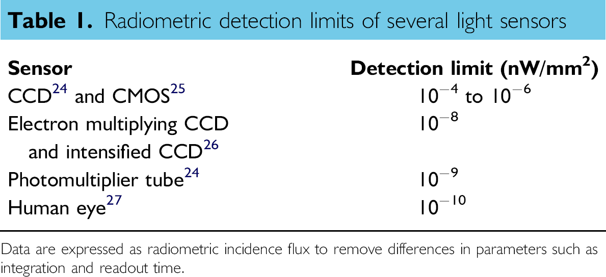
Data are expressed as radiometric incidence flux to remove differences in parameters such as integration and readout time.
Computer Control
The proliferation of inexpensive computing in the form of laptops and netbooks allows the control, acquisition, visualization, analysis, and storage of microscope images for a few hundred dollars. Communications via a data port required an interface that is ubiquitous to most personal computers, and USB was chosen. The major benefit of USB is that for the user it is largely a “plug and play” interface; very straightforward and easy to use. USB as a specification was developed originally in 1994 at Intel as an alternative to serial and parallel ports. 20 It has undergone three major versions beginning with USB 1.0 released in 1995 and began widespread use as version 1.1 in 1998 offering a data rate of 12 Mbits/s. By April 2000, USB 2.0 offered an increased data rate of 480 Mbits/s, adequate bandwidth for the user to focus the microscope in real time. In 2008, the USB 3.0 specification was completed, and earlier this year, the first consumer products were released offering effective data speeds of 3.2 Gbits/s. 21 An additional benefit of USB 2.0 specifications was the presence of 500 mA of current in high-power mode. Because LED current requirements are typically 300-400 mA, this allows the microscope to be powered through the USB cable alone. For simultaneous use of the excitation and brightfield LEDs or for a brighter excitation LED, a second USB connection for an additional 500 mA of power may be used. This greatly adds to the portability of the device when away from alternating current power. USB 3.0 offers 900 mA per connection, comfortably within the power requirements of a simple dual-mode microscope. 22
One challenge for the implementer of a USB interface is the voluminous specifications that define its rule set. Additionally, there are a number of variants of the interface that directly relate to bandwidth. As part of the development effort, a USB communications audit application was developed. Other versions of these applications exist elsewhere on the Web, but this version is written completely in CSharp, and we have made the source available to aid in the development of expanded applications. This application presents a list of all attached USB devices and hubs and provides other functionality not provided by previous offerings. These include a user interface to send and receive direct commands and responses to a USB device under WinUSB or the default human interface device library.
Results
The resulting device is a small simple box, topped by a stage with an opening for the light path to the lens. There are only three manual controls: a focus knob and two On/Off switches. The On/Off switches turn on and off the brightfield illuminator LED and the excitation LED for fluorescence mode. In the back are two USB ports (one for the brightfield illuminator and one to connect to a computer) and a power connection (Fig. 1). It is compact, portable, and easy to use, requiring that the user only turn on an LED, start the software, position the sample, and focus. This device has been simplified from typical fluorescence microscopes in that there is no filter cube selector, no light path settings required (ocular vs camera selection), no condenser adjustment for brightfield, and no external arc lamp to control. The image-capture software will be available for download onto the user's computers as a part of the microscope package. The software itself is designed to be simple and small enough that it will run easily on small inexpensive netbook computers that can follow the microscope into facilities that do not commonly house laptop or desktop computers.
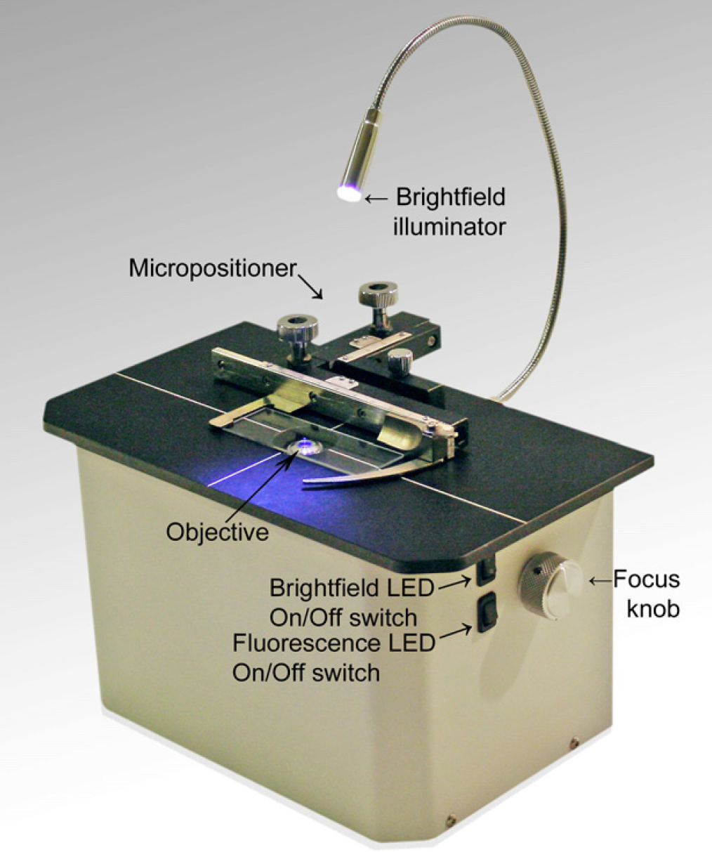
A simple, compact inverted fluorescence microscope. This device is small enough to fit easily on a bench top, desk, or in an incubator. The controls are easy to use, consisting only of a focus knob and two On/Off switches to control an optional gooseneck brightfield illuminator and the excitation LED for fluorescence imaging. An optional micropositioner is also included. A standard slide is shown clipped into the micropositioner for scale. Note the absence of a filter cube selector, a light path selector (ocular vs camera), condenser adjustment for brightfield, and arc lamp controls.
The microscope control application consists of a simple user interface enabling the adjustment of acquisition and image-capture parameters. It provides the user with a number of functions including selecting a frame rate, image output format, the manipulation and management of collected images including the editing of exchangeable image file format metadata and the ability to select areas of the image for cut-and-paste utility. User-selected configuration settings are preserved for subsequent invocations.
In addition, a simple time-lapse function allows the user to specify a frequency and duration of image capture with subsequent stitching of the individual images into a movie. This is valuable for visualizing the movement, growth, or proliferation of cells over extended periods of time. The ability to place the microscope inside a tissue culture incubator allows experiments that have previously only been available with expensive on-scope environmental chambers. The simple addition of a Web access utility like Webex allows remote monitoring of cell growth.
In the development of this microscope, standard benchmarks of magnification and resolution were defined using a micrometer and a commercially available calibration tool offered by Life Technologies (Carlsbad, CA). The TetraSpeck Fluorescent Microspheres Size Kit (Cat. No. T14792) presented multiple size and brightness beads on a single microscope slide and allowed direct comparisons with a traditional inverted fluorescence microscope. Design changes such as different LEDs, lenses, and filter sets were quantitatively evaluated for their effect on performance, and the overall performance was compared to current best practices.
The resolution of the microscope was estimated using standard methods. Figures 2 shows an image of one typical cellular preparation (HeLa cells with Chromeo 488 labeled α-tubulin) and a series of calibration images in both bright-field and fluorescence mode and the resulting point-spread function measurements from a fluorescence image. Point-spread function measurements are a convenient measurement of resolution that removes the artifacts associated with concepts such as magnification and pixel size. The imaging quality was compared with another standard fluorescence microscope. Figures 3 shows examples of images of a second commercially available cellular preparation, bovine pulmonary artery endothelial cells with AlexaFluor 488 phalloidin-labeled F-actin (Molecular Probes, Eugene, OR). Images of cells from the same slide were collected using our simple inverted fluorescence microscope and from a typical full-size, benchtop inverted fluorescence microscope for qualitative comparison.
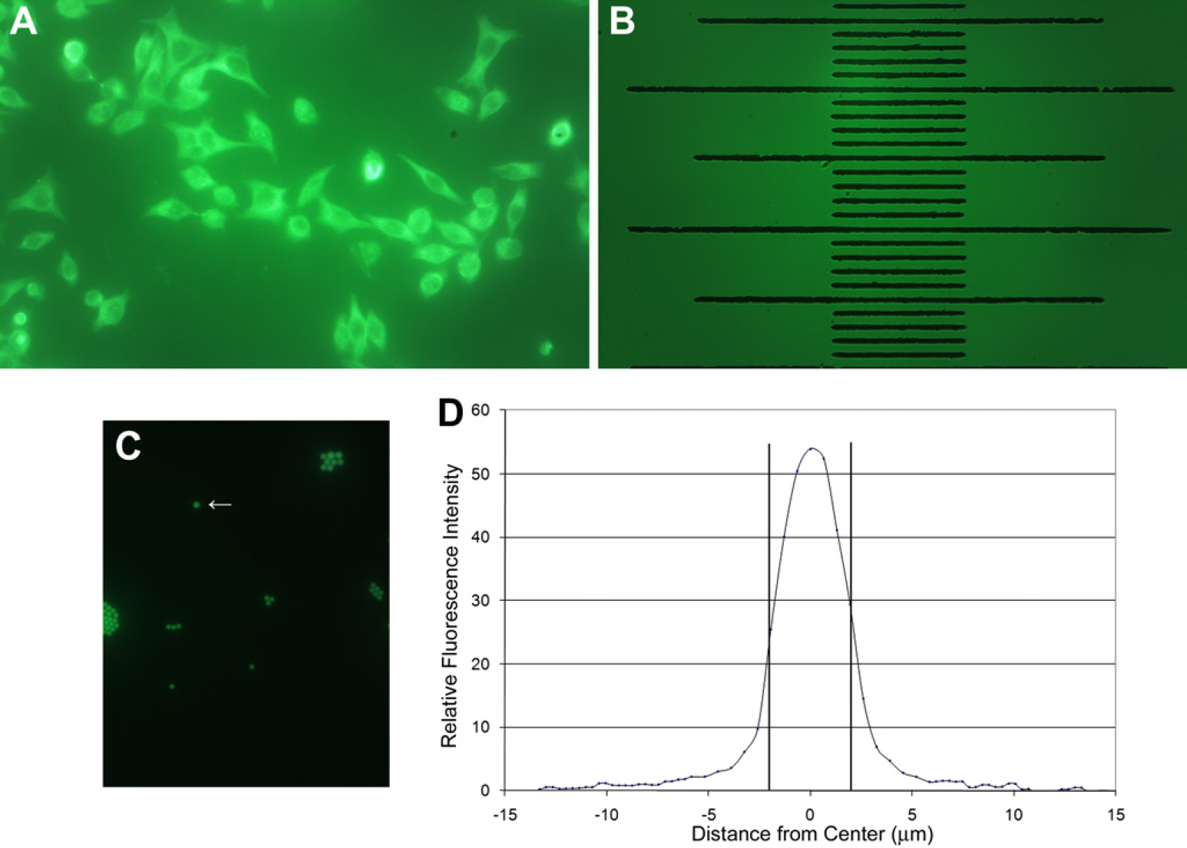
Magnification and resolution of the fluorescence microscope. (A) Fluorescence image using a 40 × objective of HeLa cells prepared using mouse monoclonal anti-alpha-tubulin in conjunction with goat antimouse IgG labeled with green-fluorescent Chromeo 488 (Active Motif, Inc., Carlsbad, CA). (B) A calibration image collected using a 40 × objective yielding an indication of magnification and measurement of field of view. The lines of the stage micrometer (Abbota, Corp., labshops.com, NJ) are 10 μm apart. The total vertical × horizontal field of view is 0. 261 × 0.415 mm. The images as captured by the camera and software are shown in their entirety in both (A) and (B). (C) An image collected in fluorescence mode using a 40× objective of 4.0
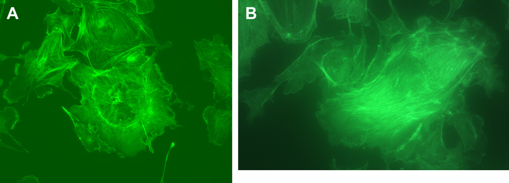
Cell image comparison. Uncropped images of bovine pulmonary artery endothelial cells labeled with MitoTracker Red CMXRos, AlexaFluor 488 phalloidin, and 4′,6-diamidino-2-phenylindole (DAPI) on a FluoCells Slide #1 (Molecular Probes) collected using (A) a Nikon (Melville, NY) inverted fluorescence microscope (Eclipse TS100) with a 40× objective and a standard green fluorescent protein filter set using a Spot camera (Diagnostic Instruments, Inc., Sterling Heights, MI) with a 20-s exposure and (B) our inverted fluorescence microscope with a 40× objective in fluorescence mode using a frame rate of 1.8 frames per second (approximately 0.5-s exposure). Note: The rapid collection frame rate of 1.8 frames per second easily allowed focusing and positioning of the sample while in fluorescence mode.
Future Improvements
The initial 488-nm fluorescence microscope can be built in several versions with other excitation colors and corresponding filter sets. The strategy is to simply have the user ask for versions optimized with different excitation LEDs and filter sets if they would like to image fluorophores that are excited and emit at other wavelengths. The images presented here were collected using a version of the device outfitted with a 40× objective. Versions with 10× or 20× objective are also available.
Future developments are envisioned both internally and through a Creative Commons license, which will encourage a community of outside developers to address specific applications and improvements. 14 23 Some additional features would necessarily increase the resulting retail price somewhat. We envision features such as autofocus, automated positioning stage, wireless communications, switchable two-color versions, and application-specific software.
Conclusions
We have successfully used recent advances in USB, LED, and CMOS technology to create an inverted fluorescence microscope with a dramatically simplified design. This device quickly and easily produces satisfactory single-color fluorescence and brightfield images. The resolution, magnification, and sensitivity have been optimized to produce an image most useful for routine fluorescence microscopy tasks, including inspection of cell presence and distribution, cell confluence, general cell health, fluorescent protein expression, and label brightness. As an open-source device and through encouragement of development of applications by users, proposed applications for this device have already expanded to include arenas such as education and commercial kit vendors. The goal was to increase access to fluorescence microscopy in many more point-of-care medical and research situations than previously possible. We achieved this goal in two ways: this device is compact and portable, and it will be immediately accessible to a wide range of laboratories with a retail price an order of magnitude lower than current standard benchtop inverted fluorescence microscopes.
Acknowledgment
The authors thank Paul Steinbach, PhD, at the University of California, San Diego for evaluating the performance of an earlier version of this device and providing valuable suggestions for modifications.
Competing Interests Statement: The authors certify that all financial and material support for this research and work are clearly identified in the manuscript.