
Abstract
DNA-based fluorescent microarrays (sometimes called “biochips”) are fast becoming the preferred tool for studying a variety of complex biochemical phenomena ranging from multiplex mutation detection, to gene mapping and expression monitoring, to high throughput screening for new drug candidates. Fluorescence is a low energy phenomenon. The need for rapid, high resolution, wide field imaging of fluorescent microarrays calls for a specialized microscope architecture. We now describe the design of a “Flying Objective” epi-fluorescence microscope that is ideally suited to this application, and compare the performance of this novel instrument with two other commercial epi-fluorescence microscopes designed to read DNA microarrays.
INTRODUCTION
The Human Genome Project is generating an enormous and increasing amount of information concerning potential genetic targets for further study. At the same time, new tools of combinatorial chemistry are being used to synthesize large libraries of different molecules. Instead of thinking about individual biochemical reactions, scientists are rapidly adopting a new paradigm in which many reactions are monitored at once, enabling the study of complex pathways and systems. Investigators involved in basic genomics research and drug discovery, however, face major bottlenecks in their ability to effectively gather and analyze all of the data from all of the experimentation that is now possible. Microarray technology has the potential to play a key role in the future of biological research by offering a massively parallel approach to the study of biochemical reactions, thereby shifting the bottleneck from data acquisition to data analysis.
Microarrays are ordered two dimensional fields of spots with a diameter between 50 and 300 microns. Typically the space between spots is equal to the spot diameter. Microscope slides, 25×75 mm or 1×3 inches, are the current standard substrate on which arrays are manufactured. In order to study effectively all of the parameters which impact microarray analysis, there is a pressing need for an affordable instrument that can rapidly and accurately scan these substrates and determine the presence and quantity of fluorescence signal at each spot in the array.
It seems almost paradoxical that the Optical Rotating Computer Memories that Terastore is scheduled to start shipping next year at about $1,000 incorporate a microscope with a resolution superior to that of the most expensive and advanced Oil Immersion Confocal Microscopes selling for well over $100,000. Adding insults to injuries, the Optical Memory device addresses a field of view of many square inches while the microscope can only address a few tens of square microns at a time.
The architecture of the “Flying Objective Fluorescence Epi-Confocal Microscope” described herein attempts to bridge this incongruity. This novel concept is applicable to a broad class of optical instruments.
BACKGROUND
The concept of a Flying Objective Microscope is quite old and is at the root of a number of instruments both driven by rotating or oscillating motors (1, 2) and by linear motors (3, 4). Unfortunately, the concept of a flying objective microscope was explored long before it could be made practical and economical. The critical features of this flying objective microscope are a novel objective concept, a periscope construction, a low cost moving magnet scanner motor and a simple focussing slide stage. Early designs (5, 6) built with CD ROM optical heads are grossly inadequate for this application.
SYSTEM PERFORMANCES
Alexay et al.(7) have tabulated the criteria for analysis of fluorescent samples. This material is reproduced here as Table 1. Included are his data for the Molecular Dynamics / Amersham (Sunnyvale, CA) AVALANCHE system. We have compared this with published data for another scanning system, the ScanArray 3000 (General Scanning, Inc., Watertown, MA), and a flying objective system, the GMS 418 Array Scanner (Genetic MicroSystems Inc., Woburn, MA). Alexay judiciously points out that uniform performance over the entire slide is “critical for precise results”. Consistent data at all locations of the field of view and for all wavelengths is the critical requirement. It should be noted that microarrays are normally imprinted on an 18 mm wide region approximately centered on a slide 25 mm wide. The FLU-AVALANCHE makes two passes to capture an image of a typical array and the two stripes are then digitally integrated into one image which yields an actual scan speed of 20 Hz.
Specifications for a fluorescent measuring system
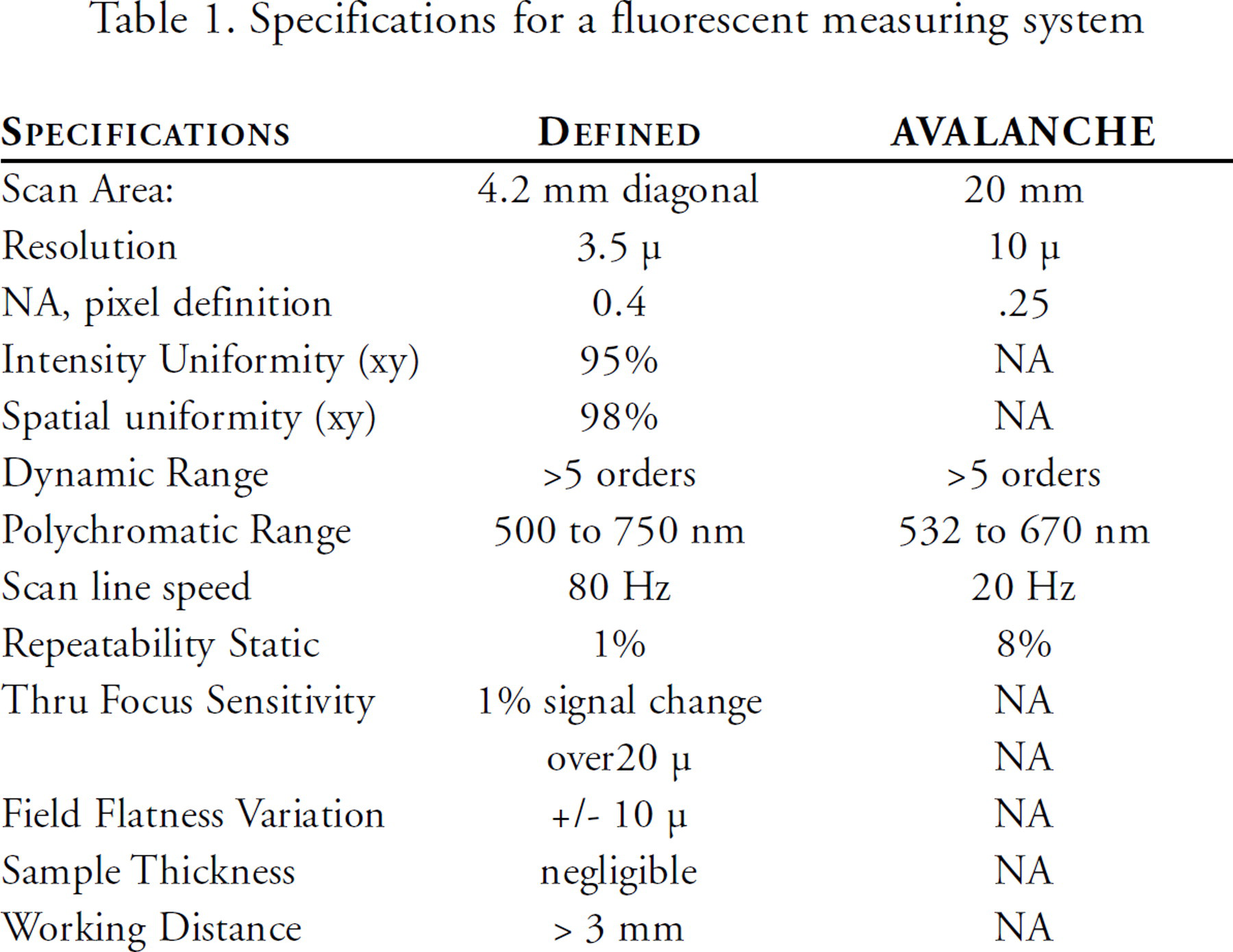
The data in Table 1 for the AVALANCHE is consistent with that of a low NA confocal microscope and as such achieves a large spot size and good background noise rejection but with a very narrow depth of field. The field flatness variation of the lens is quite large 40μm, so that the total signal error is equivalent to that of the ScanArray 3000 or the GMS 418 Array Scanner. The slide is held on a dependent motorized XYZ stage insuring proper slide location.
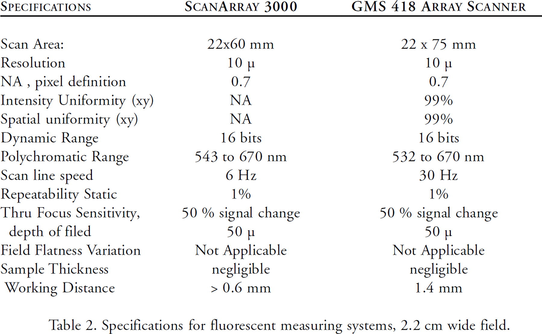
The GMS 418 Array Scanner described here (Figure 1) was designed and built with these criteria in view mediated by practical and cost considerations. It has field stops at the detector rather than a pin hole and improves the depth of field. The published performance specifications for both the GMS 418 Array Scanner and the ScanArray 3000 are listed in Table 2.
Specifications for fluorescent measuring systems, 2.2 cm wide field.
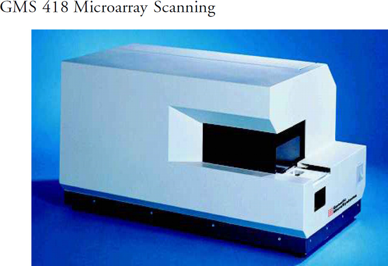
GMS 418 Microarray Scanning
OPTICAL SYSTEM DESIGN
The requirement for large dynamic range leads to a single detector design, thus eliminating multi detector systems such as linear or 2D CCD. The critical significance of repeatability and uniformity is best achieved where every slide location is addressed in an identical, and preferably telecentric, manner for both excitation and collection. This requirement has been answered by the Minsky (8) original confocal design and repeated frequently such as in the ScanArray 3000. It can best be described as a XYZ table located under a confocal microscope. Its major shortcoming is the hopelessness of achieving reasonable speed with an XY table. The ScanArray 3000 is built with a galvo driven fast axis mounted on a slower stepped Y-axis. The acceleration of higher scan rate may jeopardize the integrity of the microarray. This yields slightly more than 1/2 hour read time for a full slide at 2 wavelengths.
Faster microchip scanner designs, such as the AVALANCHE (Molecular Dynamics) uses a sophisticated 9 element field flattening lens with a rather low NA, 0.25, and consequently poor collection efficiency, about 10% of that of the GMS 418 Array Scanner, and a very narrow field of view, 1 cm. It is assembled without bonding agent in order to minimized fluorescence perturbation of the lens itself.
CLASSICAL SCANNING SYSTEMS DESIGN
The difficulties associated with both the classic microscope geometry of the Minsky design and the field flattening lens approach used in the AVALANCHE are analyzed by Alexay et al.(7). This study brings out a number of important features of both of these architectures.
The Minsky design offers a cost benefit as it is built around a commercial microscope objective (with 6 elements) but has great speed and practical limitation. The working clearance of high power objectives is quite small and the slide needs to be held reliably to avoid catastrophic interference in a dynamic environment. The slide anchor mechanism must also be light enough to permit a reasonable scan rate without excessive vibration. Finally, high acceleration may affect the experiment on the slide.
Alexay also analyzes the field flattening lens design. He gives construction details and performance of the very large 7-element lens required. He also identifies the drawbacks of this approach: high costs of both the lens and the mirror scanner and a limited field of view. Its major benefit is to offer a high-speed instrument and a simple, reliable slide handling method.
FLYING OBJECTIVE SCANNING MICROSCOPE
The critical specifications of uniformity, scan area, wavelength and collection efficiency dictate a unique optical solution. The system of Figure 2 was selected by Genetic MicroSystems, and believed to offer the most desirable choice to attain the performance defined on Table 1. As all pixels are treated in an identical manner it offers a high degree of uniformity of measurement across the field of view.
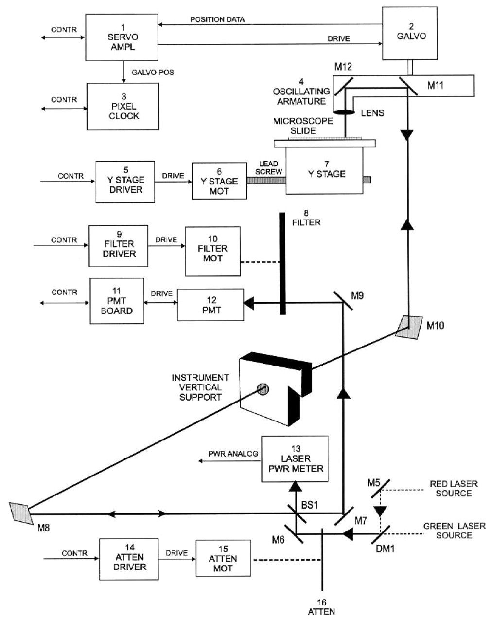
Optical System layout for the Epi-Fluorescence Flying Micro Objective GMS 418 Microarray Scanning System
A micro anamorphic one element lens is carried on a balanced arm that extends perpendicular to the shaft of an oscillating motor fitted with a position transducer. The arm also carries mirrors that receive laser light near the axis of the galvanometer via a periscope and send it out the length of the arm, and down through the lens. The arm must be dynamically balanced.
The field of view of the objective is only slightly larger than the spot size and the optical system is always on axis. Consequently this optical design eliminates all the common sources of lateral or chromatic aberrations.
The objective is built with only 2 optical elements, and only one is moving. The second one, located as close as practical on the stationary side of the periscope, corrects axial collimation and chromatic imperfections of the first element without adding any inertia. The transmission efficiency of this design is greater than 90%. No bonding agents are used in the optical path. These are the most common source of autofluorescence noise and limit short wavelength performance.
As the moving lens weighs only a fraction of a gram, the load on the galvanometer is modest. The drive signal is a 15 Hz triangular wave. Data is acquired both during the CW and CCW trajectory and synchronized via the position pickoff. This produces 30 scan lines per second and minimizes the torque requirement of the driver. The system is designed for a 75% duty cycle for image acquisition (25 ms with 2,200 pixels or 11.33 (s per pixel) and 25% for slide advance (8.33 ms between scan lines to step the slide 10 (m in approximately 16 steps).
THE PERISCOPE
The oscillating optical sub system is coupled to the stationary beams through a “periscope” on axis with the armature of the scanner. This does not require critical alignment as the light beam at this stage is collimated and the motions are periodic. Any misalignment would be reduced by the magnification ratio.
STAGE, SLIDE HANDLING, AUTO-FOCUS & ROBOTIC INTERFACE
The slide handling is a critical aspect of all microscopes, especially when auto loading is concerned. The industry standard has defined slides and stages such that slides are supported from their back and brought into focus. A number of automatic focusing algorithms have been standardized and are well accepted.
A low numerical aperture (NA) optical system such as that of the AVALANCHE, has a depth of field an order of magnitude greater than that of the other scanners and can accommodate all slide thickness without adjustment (but also has fluorescence collection efficiency lower by the same ratio).
The ScanArray 3000 handling mechanism forces the microscope slide against stops in order to bring in focus the surface to inspect. This excludes the use of cover slips, fluids or any function over the glass as well as any non-glass substrate. It also complicates any auto-loading interface.
The GMS 418 Array Scanner offers a simple and novel slide-handling concept integrated with the flying objective design. The oscillating mechanism maintains the objective lens in a plane normal to the axis of rotation. If the slide is held in a second plane, the two planes intersect to form a line. The design holds that line normal to the axis of rotation, and normal to the line of symmetry of the scan motion. Under these conditions, it is possible to tilt the plane of the slide to focus the slide and keep it in focus as it translates under the objective. Figure 3 diagrams this focusing method. It has a stepper motor (with manual override) for auto-focus. Focus is sensed by measuring the high frequency components of the light reflected by the sample.
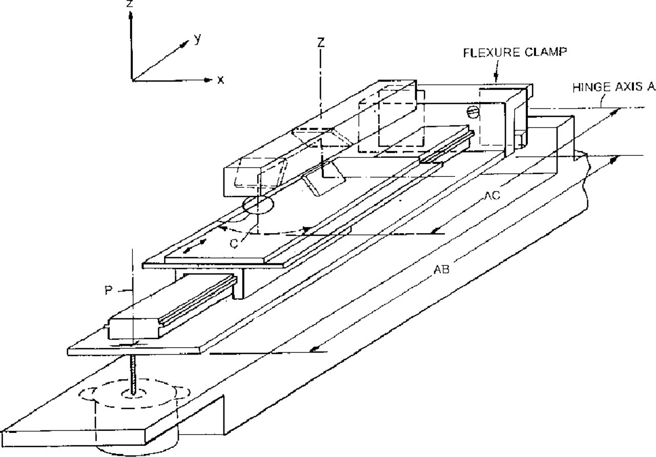
Tilt Plane Stage with Auto-Focus
CONTROL & SCANNING COORDINATE CONVERSION
Control of the microscope is accomplished via a PC based DSP controller board containing A/D's, D/A's and digital I/O. The user interface is a flexible yet simple Windows 95/98 GUI (Graphical User Interface). The GUI provides the operator an easy means for controlling the stage position and motion for inserting/extracting/scanning of slides, selection of excitation sources and power levels, and Photomultiplier Tube Gain (Anode voltage). The control software automatically selects the appropriate emission filter.
Once the desired scanning parameters have been set, a controller D/A channel outputs the triangular scanning drive signal to the galvanometer. A pixel clock, located in the microscope, uses the position feedback from the galvo to produce the needed pixel and line sync information to drive the A/D channels and control the motion of the stage between scan lines. Fluorescence and laser power signals are acquired for each pixel in order to enable normalization of fluorescence data to fluctuations of excitation power.
PMT and laser power signals are processed through matched, sophisticated high order, phase corrected analog filters before being digitized in order to provide enhanced signal to noise performance and anti-aliasing.
Since the collection lens trajectory is actually an arc rθ coordinate system), the final display and data files must be converted to Cartesian coordinate form. The conversion is performed automatically by the DSP processor after the completion of the scan. Therefore viewing and data analysis is accomplished using conventional means.
CONCLUSION
The GMS 418 Array Scanner is an application specific instrument demonstrating the capability of the Flying objective microscopy concept. Figure 4 is a portion of large array with many levels of varying intensity that demonstrates the range and resolution of the instrument. This concept offers an extremely attractive option when it is necessary to capture a high resolution image or data file of a large field of view, providing enhanced speed and sensitivity with an inherently low cost and reliable mechanical design. The basic concept has been incorporated with equal success in another large field of view microscope built with a 100 Hz scan rate and a 0.5-micron resolution that addresses a 1-cm square field.
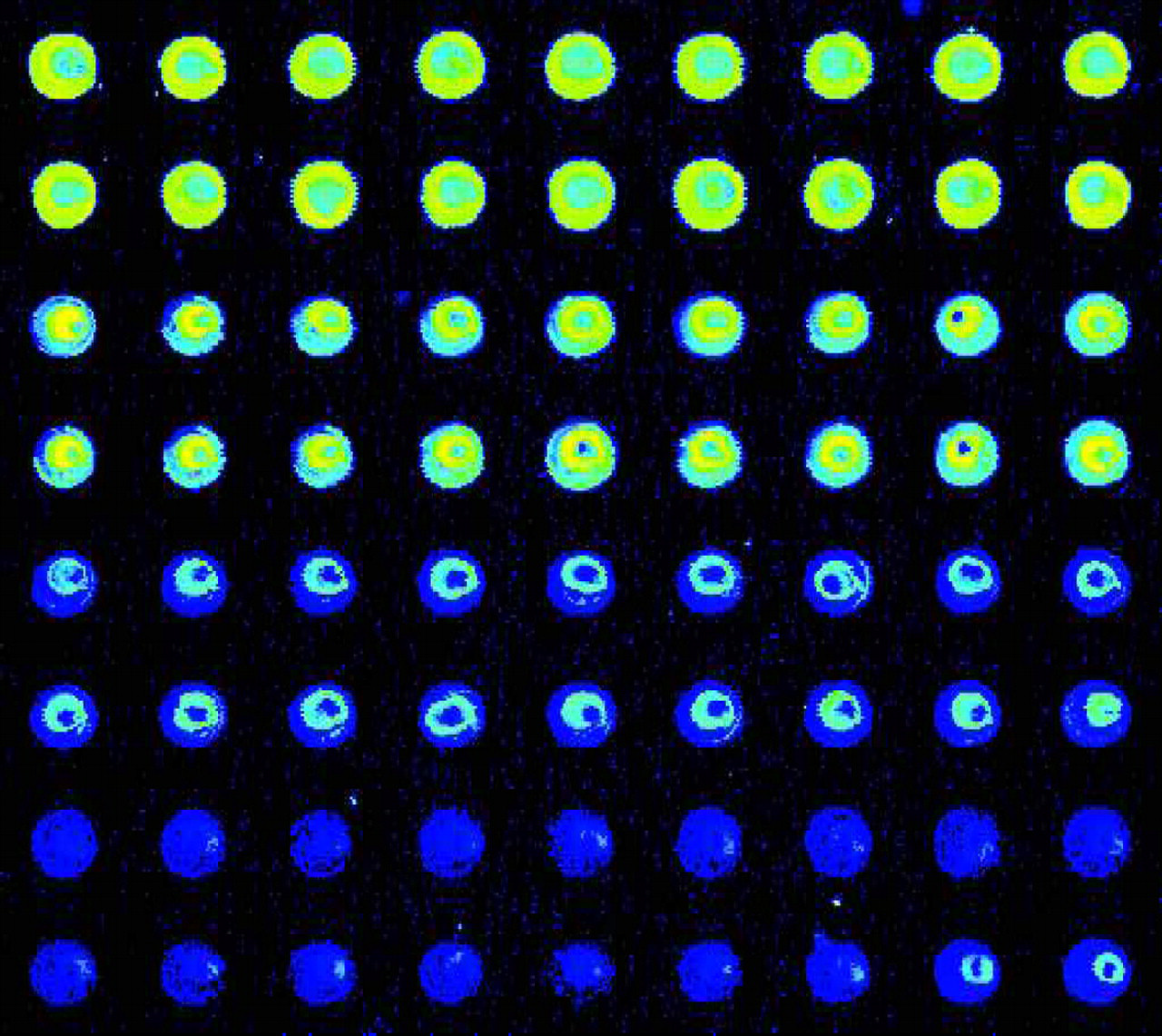
Portion of a typical array stained with Cy5