
Abstract
A mechanism for controlling the mixing of highly viscous biosamples at the microliter scale is presented. Existing methods for mixing biosamples using microstirrers or shaking microwells are only effective for non-highly viscous materials. The proposed mechanism mixes monoolein, a highly viscous biosample, with water/membrane protein solution in a microdevice called microcapsule using a microchannel and centrifugation. To achieve effective mixing, the design of the microcapsule along with the microchannel is presented and so is the hydrodynamic model describing the flow of viscous materials in the microchannel. The mixing process is analyzed according to the Reynolds number of the biosamples using computer simulation, which is observed during the experiment using digital images for further analysis. Finally, the new approach is verified by X-ray diffraction experiments with water and the Rh membrane protein solution, which are used to evaluate the effectiveness of mixing. Experimental results not only validate the proposed method but also determine the flow oscillation time in the microchannel to achieve effective and efficient mixing.
Introduction
In recent years, the technology of micromixing has attracted a great deal of attention because of the applications in life sciences, analytical chemistry, and food engineering. Here, micromixing means that the volumes of the samples to be mixed are at the microliter (1 μL = 10−6 L) scale. For example, in the field of life sciences, micromixing is involved in the process of membrane protein crystallization, which is a necessary step for determining the structure of the protein using X-ray crystallography. There are a number of methods that can generate high-quality crystals of proteins for the purpose of X-ray crystallography, and in general, these methods fall into two categories. 1 The first category is the in surfo method that was introduced 20 years ago. The method has been proved difficult to crystallize membrane proteins because it is attempted as for soluble proteins and thus detergents are needed to solubilize membrane proteins, which cause low success rate because of the conformational inhomogeneity of the membrane proteins. 2,3 The second category is those that use a lipidic cubic phase called the in meso method as an alternative. In the in meso method, an extended bilayer composed of lipid, detergent, and target protein is presumed to form. It constitutes the following two steps for growing crystals: 4,5 (1) mix two parts protein solution/dispersion with three parts lipid (usually monoolein [1-oleoyl-rac-glycerol, lot M-239-M8-R]), and the cubic phase forms spontaneously, (2) add precipitant/salt and incubate, and crystals form in hours to weeks. All operations take place at 20 °C. 5
The in meso method was proved effective for the purpose of crystal growth. 1 The method however requires a highly viscous lipid (monoolein) to be mixed with the protein solution (such as bacteriorhodopsin). Mixing in this manner produces a biosample having the cubic phase structure, which is the medium required for crystal growth. According to the water-composition graph of the monoolein—water system shown in ref. 4, the relevant phases such as the Pn3m cubic phase could form at 20 °C when the weight of the water is between 39% and 41% of the total (Fig. 1). The cubic phase is then dispensed into an array of wells on a plate as part of the crystallization setup. 1,5,6 The crystal formed in the wells can be harvested and used to determine the 3D structure of the protein using X-ray crystallography. 7 –11
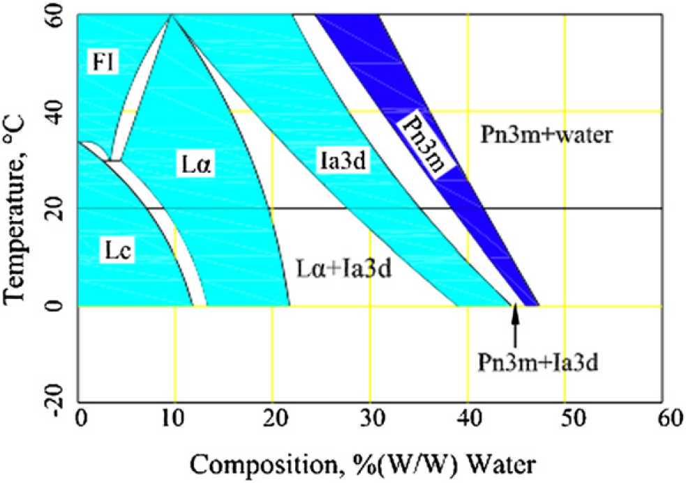
Water-composition phase diagram for the monolein and water system. 1
A robotic system for automating the delivery of viscous biosamples into arrays of wells has been built in our laboratory, 10 –14 which has significantly increased the efficiency and quality of dispensing. Unfortunately, the mixing of the lipid and protein was still done by hands using two microsyringes. 1 Even worse is that this manual process must be done one sample at a time, which is tedious and time-consuming.
In reviewing the literature, no work was found for mixing highly viscous materials at the microliter scale. Conventionally, shaking has been a way for mixing at a small volume scale since 1940s. 15 The approach is still widely used in the laboratories today for various purposes. A shaking system includes either shake flasks or microwell plates. Shake flasks may have a volume ranging from 10 to 500 mL 16 and can be made out of glass or plastic. Some have baffles to aid mixing. Liquids in shake flasks can be agitated using either orbital or linear shaking. The factors that affect flask mixing include vessel size, fill volume, shaking frequency, and liquid viscosity. Microwell plates on the other hand have been widely used in life sciences for more than 50 years. They can handle mixing in parallel and at a scale ranging from 0.1 to 5 mL in each well. 17,18 In general, orbital shaking of the entire plate is the most common method although mixing can be achieved using pipette aspiration or magnetically agitated stirrer bars. 19 The number of wells contained in a microwell plate is typically 6, 12, 24, 96, 384, 1536, or 3456. Unfortunately, plate shaking is still primarily used to handle low-viscous solutions, such as bacteria, fungi, and mammalian cells. For highly viscous biosamples, shaking is not effective.
Stirring is a common technique for mixing, which consists of a motorized agitator to cause the liquid to move or shift with a turbulent motion. The technique has been used in chemistry, food, biology, and pharmaceutical industries. In recent years, efforts have been made to design miniature stirrers and drivers such that the volume of the solutions could be reduced. A number of methods using microstirrers for mixing at the milliliter level were found. Lamping et al. 20 designed a miniature bioreactor for automated bioprocessing, which has three mechanical microstirrers (impellers) to mix the samples, and the working volume of the bioreactor is 6 mL. Commercially available bioreactors on the other hand can be as small as 10 mL, 21,22 which are also equipped with microstirrers. Furthermore, the stirrers could be driven by either electric motor or magnetic field. The latter is more attractive for miniature bioreactors because no physical coupling is needed between the microstirrers and the drivers. 21 Unfortunately, all the reactors as reported in ref. 20–22 are designed for nonviscous solutions (viscosity is significantly less than 3000 cP). The major challenge in using the microstirrer is that the viscous sample could stick to it when the stirrer is moved.
Another method for liquid mixing is by mechanical channels, which use T-shape, 23 Y-shape, 24 and slit-type interdigital homogenization, respectively. 25 Mechanical-channel mixing is designed for mixing low viscosity and high volume liquids, which are pumped through the channel continuously. It is not suitable for mixing highly viscous biosamples at the microliter scale. The literature suggests that mixing high viscosity (>3000 cP) and lower volume (<10 μL) biosamples, such as lipid dispersions for crystallization of membrane proteins in a high-throughput manner, represents a great challenge and has not been seriously addressed by either the life science or control community.
In this article, we present an approach for mixing a highly viscous biosample (monoolein) with water/Rh membrane protein solution at the microliter scale. The method makes use of a microdevice that is structured as a two-compartment microcapsule built in with a microchannel, through which the water can travel back and forth under centrifugation. The compartments serve as a container for promoting and mixing biosamples. Because of the centrifugal force, one sample (the water) flows through the microchannel to mix with the other without any mechanical parts to stir the samples. The combination of these innovative ideas enables the effective mixing of highly viscous biosamples.
This work is based on our previous effort, which has been published as a conference article. 26 In the previous work, the hydrodynamic model of the flow of viscous materials in the microchannel was developed, and the flow of viscous biosamples in the microchannel using centrifugation was described. 26 In this article, we expand the results in ref. 26 to address the issues related to the control of centrifugation and the mixing process. We will present the physics of the flow of viscous materials in the microchannel, the control of the centrifugation, the analysis of the mixing process through computer simulation, and the evaluation of the proposed mechanism through experiments including the use of X-ray diffraction.
The article is organized as follow. The design of the micro-capsule is introduced in the Design of the Microcapsule for the High-Throughput Mixing section. The hydrodynamic model of the flow of viscous materials in the microchannel and the control of the flow of viscous biosamples in the microchannel are described in the Hydrodynamic Model of the Flow in the Microchannel section. The mixing of monoolein and water system in the microchannel is analyzed in Hydrodynamic Model of the Flow in the Microchannel section with the aid of computer simulations. In the Analysis of Mixing Process of Monoolein and Water section, experimental processes and results using X-ray diffraction are presented. Conclusions are presented in the Experiments section.
Design of the Microcapsule for the High-Throughput Mixing
Design of the Single Microcapsule for Mixing
The microcapsule has two functions. First, it houses the biosamples in a compartment, where the crystal can grow. Second, it provides means whereby the contents of the capsule can be mixed in a simple and programmable way. To simplify the fabrication, the microcapsule is designed to have a cylindrical shape. To accommodate the above two functions, the basic structure of the microcapsule is shown in Figures 2. It has two compartments and a microchannel connecting them. The compartments are for holding the biosamples, whereas the microchannel is for the samples to flow back and forth between the two compartments. Mixing is achieved when the materials flow through the microchannel together as shown in Figure 2D, or the turbulence flow of one sample (the water) diffuses itself into the other sample effectively. Each compartment has an access port for loading and unloading samples.
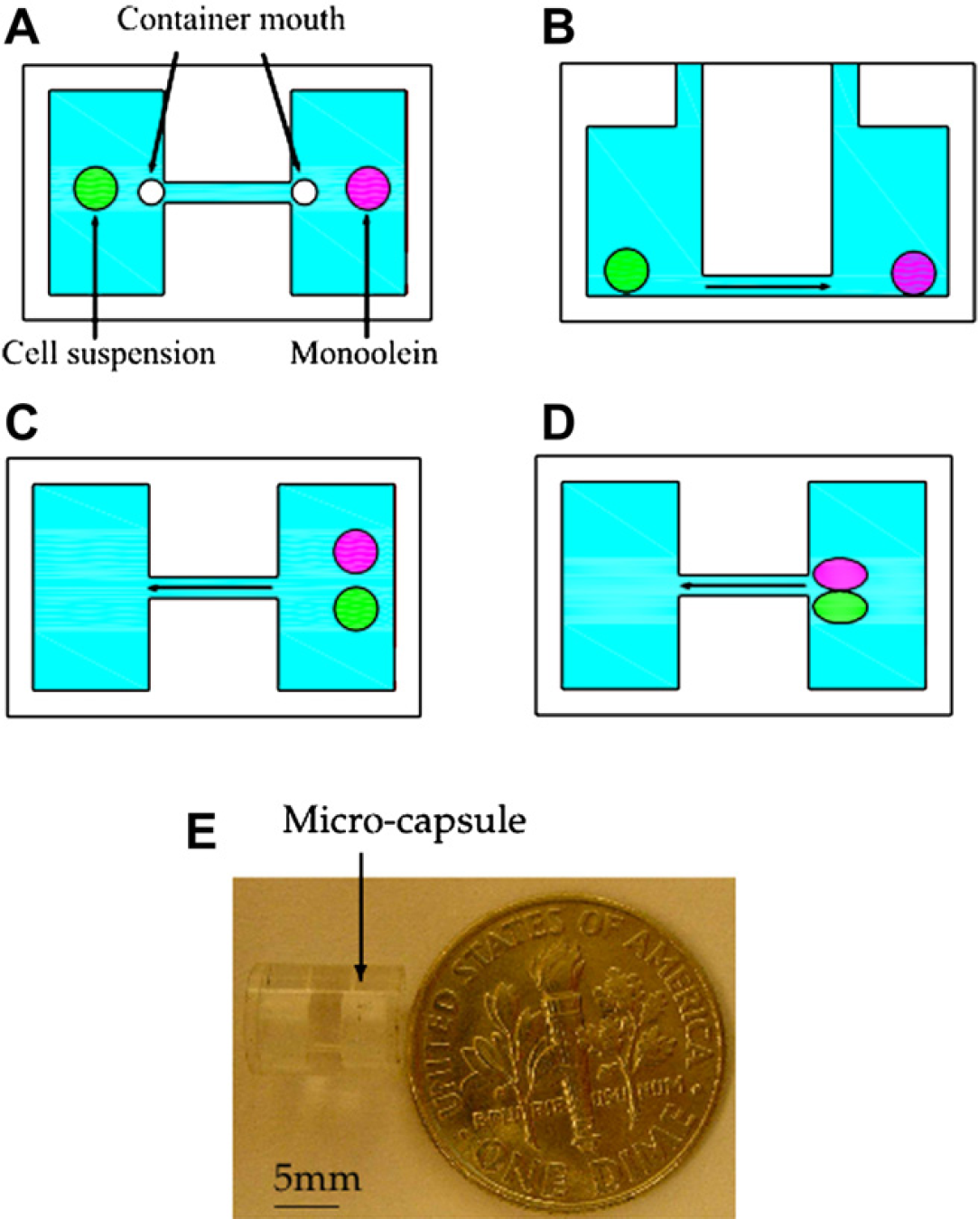
Microcapsule for mixing two biosamples cell suspension and monoolein: (A), (C), and (D) are the top view, (B) is the side view, and (E) shows the actual microcapsule. Note that a microchannel connecting the two chambers and each chamber has a mouth to serve as the access port.
Two considerations determine the dimensions of the microcapsule. First, the size of the compartment should be compatible with the volume of the biosamples to be handled. Then, the length and diameter of the microchannel should enable adequate flow of the samples for effective mixing. In general, there are two types of flow in the microchannel, laminar or turbulent, which are differentiated by a measure called Reynolds number (Re). The Reynolds number is the ratio between inertial (


In Eq. (1), ρrH is the fluid density, d is the channel diameter,

Laminar flow, which is characterized by smooth and constant fluid motion, occurs at low Reynolds number, where viscous forces are dominant, whereas turbulence is characterized by random eddies, vortices, and other flow fluctuations that the flow generates. Turbulence flow is more effective for mixing because the random eddies or vortices can increase greatly interfacial area of two samples. Generally, micromixers are characterized by geometries with a low Reynolds number. In such microscale, turbulence flow is hard to achieve, especially, for highly viscous materials or low velocity, and mixing relies on diffusion. However, if a special design is considered, such as a microchannel, driving agitator, or magnetic bar, diffusion time could be reduced or turbulence may even be generated.
In our designed capsule, the long and narrow channels are used for water to generate the turbulence while the force driving the flow is by centrifugation. The turbulence of the water enables it to jet into the monoolein compartment, and monoolein can be smashed by water for diffusing. The viscosity of the mixture such formed in the monoolein compartment is decreased because a low-viscosity sample (the water or the membrane protein solution) mixes with a high-viscosity sample (monoolein). 29 –32 When the flow direction is alternated, the remaining water in the monoolein compartment comes back by centrifugation and is ready for a new jet again. After a few times of alternation, the viscosity of the mixture is decreased to such a low level that it can be shaken in the compartment for continuing mixing under centrifugation until the homogeneous mixture is achieved. Figure 3 shows a microarray plate that can achieve parallel operation of multiple capsules installed on the plate.
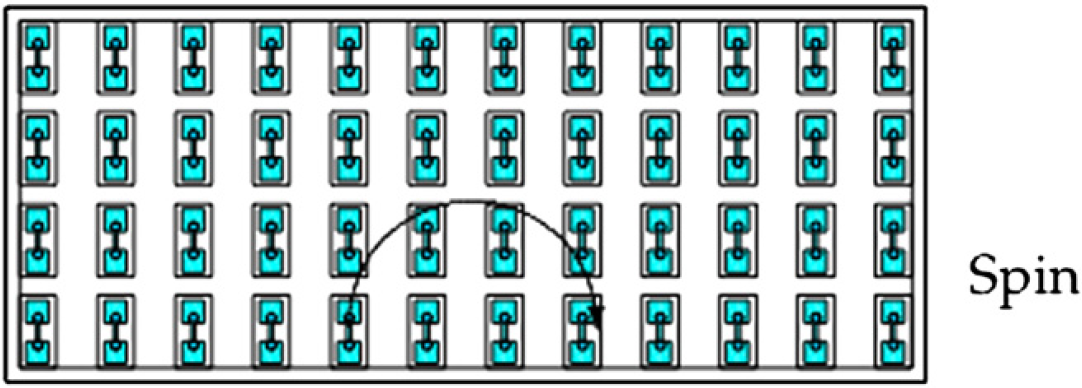
The plate with an array of microcapsules spins in a centrifuge.
We consider the length of the microchannel to be about the same as that of the compartment, and the volume of the compartments around two to six times the volume of the biosamples. These considerations are all ad hoc so long as the compartments can hold the biosamples, and the microchannel can produce turbulence flow under the available centrifugation device. In the experimental studies, our prototype microcapsules have two compartments each with a length of 2.5 mm and a diameter (42) of 4 mm. That will create a volume of 31.4 μL. The microcapsule is thus suitable for holding 5–15 μL biosamples. Subsequently, the microchannel is designed to be 2-mm long, and the diameter is chosen to be 0.4 mm for which the reasons will be discussed in detail in the Analysis of Mixing Process of Monoolein and Water section. The other dimensions of the microcapsule are shown in Figure 4.
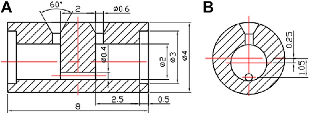
The dimension of the microcapsule: (A) front view and (B) side view where the units are in millimeters.
Design for the High-Throughput Purpose with Multiple Microcapsules
Figure 5 shows the mechanism for high-throughput mixing of a large number of microcapsules. It consists of a round disc installed with 16 plates along the edge. Each plate has multiple microcapsules arranged in an array of 4 rows and 12 columns as shown in Figure 3. The question is if each microcapsule will receive the same driving force when the disc rotates for the centrifugation purpose. To answer the question, the following analysis is in the order.
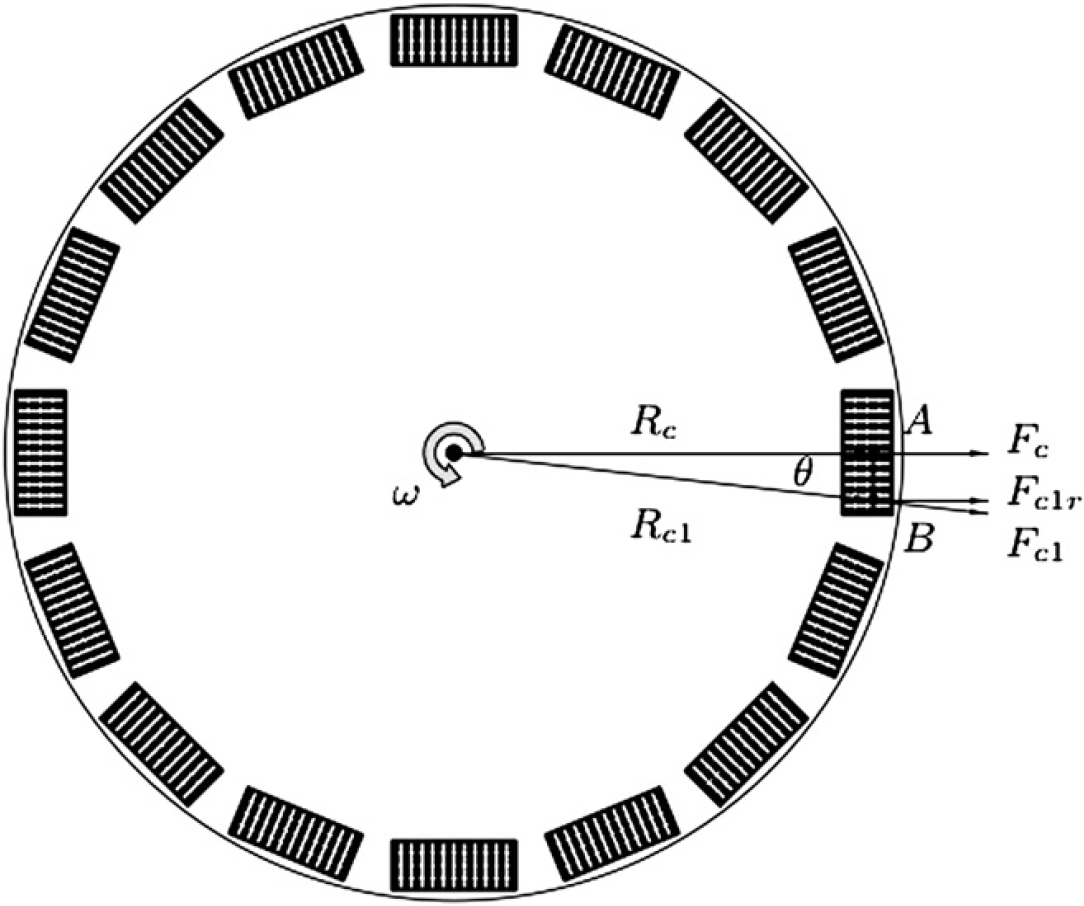
The centrifugal forces applied to multiple plates for high-throughput mixing.
Consider two capsules on a single row A and B. A is closest to the center of the disc, where the axis of spin is, with a distance R c , whereas B has a distance R c1 . The two distance vectors form an angle θ. The relationship between R c and R c1 can be defined by the following equation:


From F

Eq. (5) indicates that the centrifugal force acting on any microcapsule of the same row is identical. However, the centrifugal forces acting on different rows are different because of the variation of the distance from the center of the disc, which may affect the uniformity of the mixing. To avoid this problem, two approaches can be taken. First, only a few rows are allowed on a plate such that the distance of each row from the center R
Hydrodynamic Model of the Flow in the Microchannel
The approach we propose is to let the biosamples travel though the microchannel such that mixing can be achieved. To understand how the biosamples flow through the micro-channel under the effect of the centrifugal force, we need to develop a mathematical model to describe the hydrodynamic behavior. Once the model becomes available, the type of flow, laminar or turbulence, can be recognized.
To develop the model, a brief description of viscosity is appropriate. From ref. 26, viscosity can be understood from a viscous material sandwiched between two flat plates separated by a distance y as shown in Figures 6. When the upper plate moves horizontally with a velocity v and the lower plate remains stationary, the velocity of the material decreases linearly from v at the upper plate to 0 at the lower. To create such a velocity gradient, a shear force F must be applied to the upper plate, which is proportional to the coefficient of viscosity, the velocity gradient (or shear rate) of the material dv/dy, and the area of the plate A:
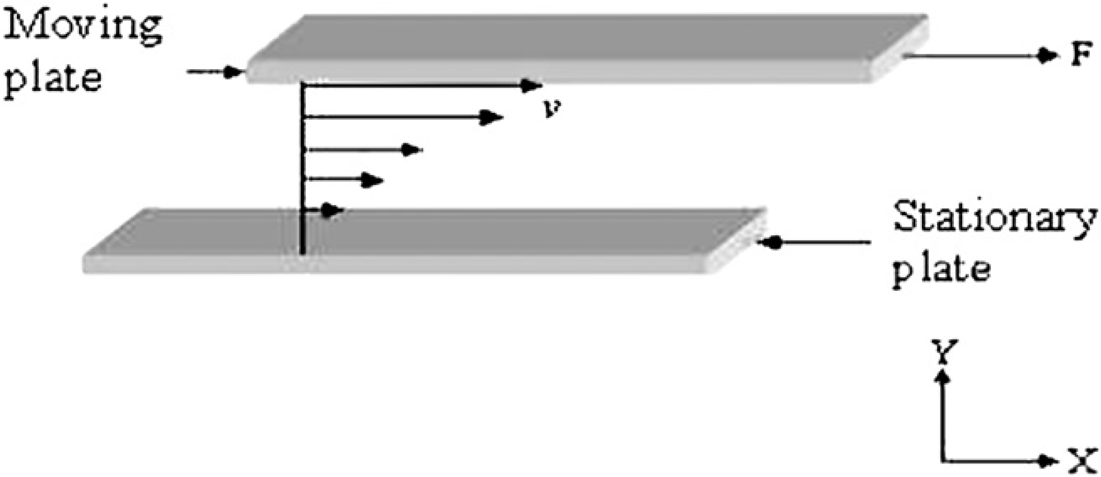
Two parallel plates move with relative velocity v when the space between is filled with viscous material.

The model of the viscous material flowing through the microchannel can be built based on the viscosity model of Eq. (6). Assume a microcylinder of length δl that is as long as the microchannel and radius δ within the microchannel (see Fig. 7). The axis of the microcylinder is coincident with the axis of the channel. The centrifugal force acting on the bio-samples in the microcylinder can be described as follows:
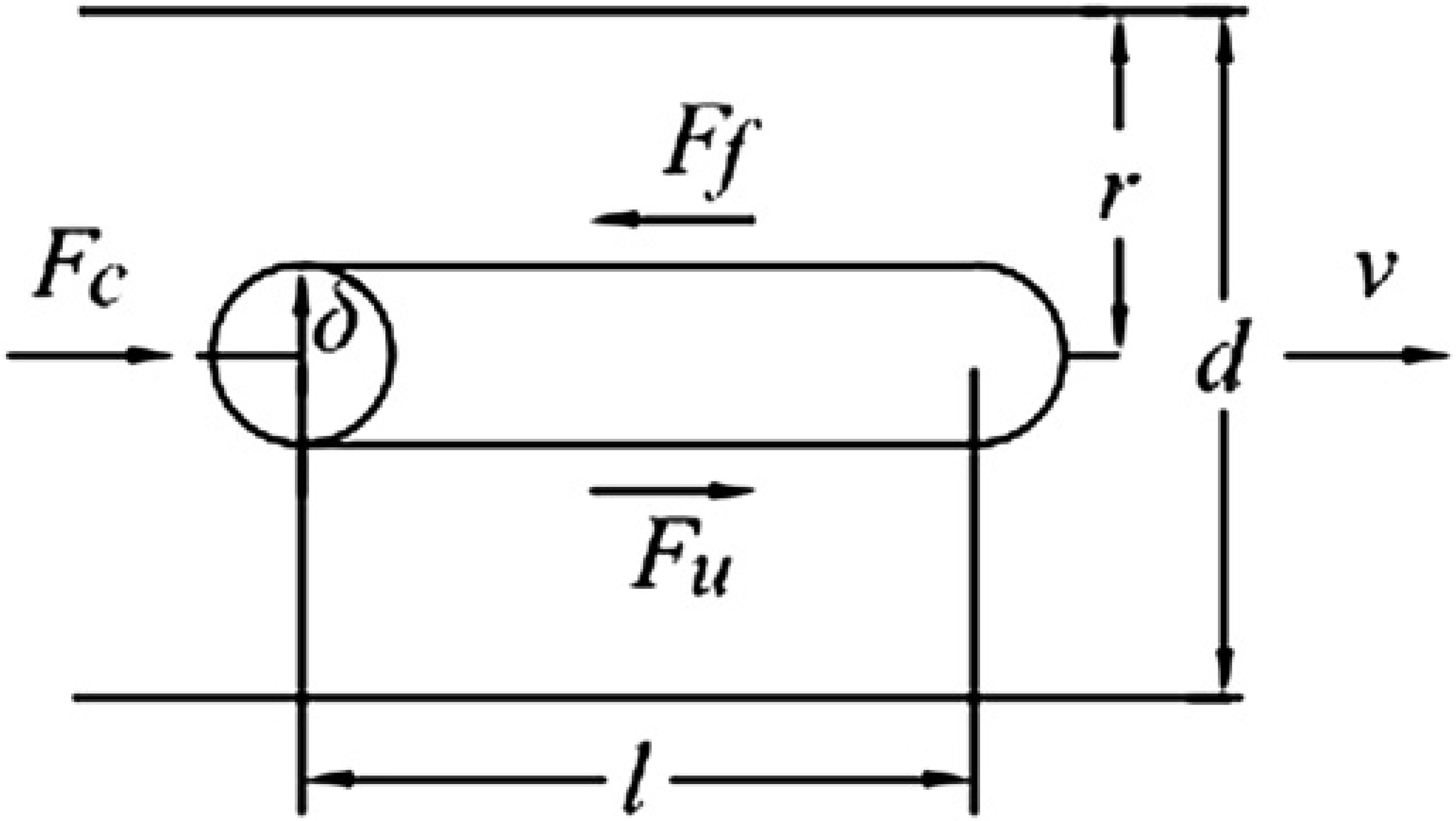
The hydrodynamic model of the flow of viscous bio-sample in the microchannel.

where m: mass of the biosample in the microcylinder; ω: angular velocity of the centrifuge; and R c: the distance between the center of rotation and the microcylinder.
According to Eq. (6), the sheer force F u, due to viscosity, is

There also exists frictional force between the surface of the channel and the viscous material because of the roughness of the surface. The frictional force F

where the undefined parameters are

Thus, when the material flows, the summation of the frictional force F
f
and the shear force F
u
must be equal to the centrifugation force F

From Eqs. (8) and (Eqs. (10)), we can obtain the velocity along the radius:

Based on the boundary condition that v = 0 when ρ = r, we can integrate Eq. (11) to obtain:

Eq. (12) shows that the velocity of the flow in the microchannel has a logarithmic distribution along the microchannel radius r. The maximum velocity is on the axis, and the minimal occurs on the wall of the microchannel where ρ = r.
In Figures 6, we can take a small circular area of dδ at a radial position δ to obtain dB = 2πδdδ. The flux through the circular area is

Substituting v in Eq. (13) by Eq. (13), one obtains:

Integrating Eq. (14), one obtains:

Thus, the average velocity in the microchannel can be expressed as:

Making use of Eq. (9), Eq. (16) becomes:

Eq. (17) indicates that the average velocity of the material is directly proportional to the centrifugal force and inversely proportional to the channel length and the liquid viscosity.
Analysis of Mixing Process of Monoolein and Water
As mentioned earlier, one important application of the current method is for crystallizing membrane proteins. It has been shown that the so-called in meso method is effective for crystallizing membrane proteins and has been used in the field of biochemistry for a long time. 4,5 The key of the in meso method is the homogenous mixing of protein with lipid and the formation of the cubic phase. There are several different types of the cubic phase, for example, Lc, Lα, cubic-Ia3d, and cubic-Pn3m as shown in Figure 1. Each has its own characteristic low-angle diffraction pattern under the X-ray, 2 which is used to index the corresponding space group (Pn3m, Ia3d, etc). It is not clear which of the cubic phases is required for crystal growth, but the cubic-Pn3m phase predominates which crystals grow and has proved to be a useful medium for the growth of well-structured crystals of membrane proteins. 34,–36
In our work, we use pure water and membrane protein solution to mix with monoolein because the viscosity of the water is very similar to that of the membrane protein solution. Monoolein on the other hand is a mixture of glycerides of eleic and other fatty acids, consisting mainly of monooleate. Its density is similar to honey, but its viscosity is much higher than the latter. Fundamentally, we need to understand how water or monoolein flows through the microchannel under centrifugation.
The relationship between the average flow velocity (


The centrifugal force is expressed as below:

From Eqs. (18) and (19), the Reynolds number can be calculated:
In our work, 200 g (n = 800 rpm) of the relative centrifugal force (rcf) and 90 s of the duration time are used for each mixing. There are two reasons for this use: one is that 200 g rcf is a low laboratory centrifugation and easy to operate, and the other is that the combination of 200 g rcf and 90 s is enough for the samples to flow through the same micro-channel. 26 If these parameters can mix monoolein with water well, a larger centrifugation or longer duration is also qualified for the mixing. For the given dimension of the microchannel and the spin speed n = 800 rpm, the 5-μL water flowing through the microchannel has a Reynolds number of 3200, but the Reynolds number for monoolein is rather small (less than 100) because of its high viscosity. In fact, the velocity of monoolein is close to zero in the microchannel (<10−6) according to Eq. (17). Thus, our mixing strategy is to let water travel through the microchannel in a high velocity to mix with monoolein by diffusion as discussed in the previous section.
Analysis of the Microcapsule Design
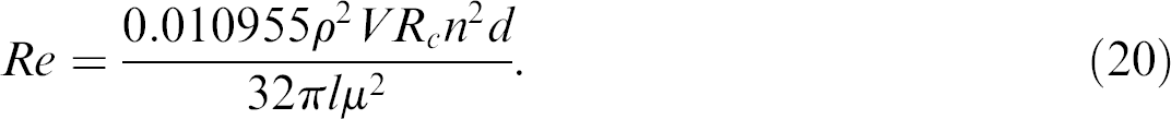
According to the Reynolds number, the length and diameter of the microchannel should be optimized to guarantee the turbulent flow of water. For the turbulent flow, the Reynolds number of water should be greater than 2300. Based on Eq. (20), the ratio of the channel diameter and length must satisfy the following equation for the turbulent flow:
In the design of the microcapsule, the length of the microchannel is selected using the following principle. It is fundamentally constrained by the dimension of the microcapsule, which is determined by the space limitation of the plate that holds the microcapsules and the volume of the biosamples to be mixed. According to the space limitation, the size of the microcapsule is determined. Then, the volume of each compartment in the capsule is determined according to the volumes of the two samples to be mixed, that is, the former should be greater than the latter. As a result, the distance between the two compartments can be determined by the two factors, the volumes of the biosamples, and the size of the plate. For our applications, the length of the microchannel is selected to be 2 mm as cited earlier. Once the length of the microchannel is selected, only the diameter of the microchannel can be optimized to reach effective mixing. In the following, we discuss how the diameter of the microchannel can be optimally selected.
For effective and efficient mixing in the microcapsule, two factors are critical: turbulence flow and enough smashing time. First, the flow of the water in the channel should be turbulence because turbulence flow generates large eddies and vortices, which can smash the viscose biosample for effective mixing. Second, the jet of the water should be as long as possible. The reason is that mixing is more effective when a constant volume of water can smash the viscose material for a longer time. To satisfy the first factor, the diameter of the microchannel should be greater than 0.288 mm for turbulence flow according to Eq. (21). The second factor needs the diameter to be as small as possible because that will prolong the time of flow. Consequently, there is a compromise between the two factors, that is, the optimal design is to push the diameter to the lower bound as much as possible such that the flow of the water is turbulence while the time of flow is long.
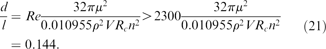
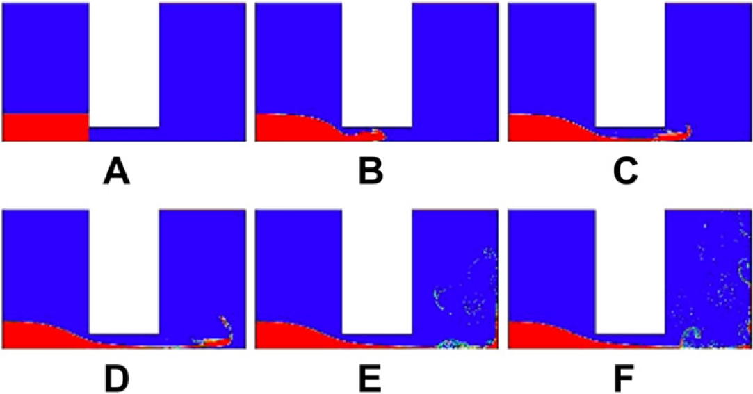
To prove the theory of the optimal diameter of the microchannel as just described, three different sizes of the diameter, 0.2, 0.4, and 0.8 mm, are used to simulate the flow of the water through the microchannels by Computer Fluid Dynamics simulation package called FLUENT. It is clear that 0.4 mm is closest to the lower bound of the diameter that is 0.288 mm. The results are shown in Figures 8–Figures 10, respectively. Figures 8 shows less eddies and vortices because the flow is laminar as the diameter is less than 0.288 mm. In comparison, the flows depicted in Figures 9 and Figures 10 are turbulence. Figure 10 shows a larger flux flowing through the microchannel than the flow in Figure 9, which means that the water will be more quickly exhausted in the 0.8-mm diameter. Figure 9 shows that the 0.4 mm can guarantee eddies and vortices and as the same time the water can jet for a longer time than the 0.8-mm diameter for the purpose of smashing, which means more effective mixing.

The water flowing through the microchannel of 0.2mm diameter at: (A) 0 s, (B) 0.0001 s, (C) 0.0002 s, (D) 0.0003 s, (E) 0.0004 s, and (F) 0.0005 s, which show laminar show.
The water flowing through the microchannel of 0.4mm diameter at: (A) 0s, (B) 0.0001s, (C) 0.0002s, (D) 0.0003s, (E) 0.0004s, and (F) 0.0005s, which show turbulence flow with large eddies and vortices.
The water flow process through the microchannel of 0.8-mm diameter at: (A) 0s, (B) 0.0001s, (C) 0.0002s, (D) 0.0003s, (E) 0.0004s, and (F) 0.0005s, which show turbulence flow, but the flux of the water is quicker than the 0.4-mm diameter as the water level is lower in (F).
In addition, in the multimicrocapsules plate, the Reynolds number of the shortest centrifugal radius row is 2816 according to Eq. (20), which still guarantees the turbulence flow of water.
Analysis of the Mixing Process
The available literature reveals that the most common and simplest way to determine the quality of mixing is by the flow visualization technology such as photo or video techniques to monitor the mixing process. 37 To make sure that the mixing progresses according to what has been analyzed, we propose to perform a real mixing experiment in which dyed water is used for clear observation and observe the process using digital images. The water is initially dispensed into the right compartment and monoolein the left as shown in Figure 11A. For convenience, each flow motion of the samples under centrifugation is called one time of mixing (TOM), and digital photos are taken at the end of a TOM. Figures 11B#x2014;J shows the sequence of the mixing process including eight TOMs under centrifugation. The whole mixing process is divided into three stages. In the first stage, the water travels from its compartment through the microchannel to reach monoolein in the left compartment. Because of the turbulence flow of the water, the water turns itself into eddies and vortices, which are jetted into the monoolein compartment and smash monoolein against the wall as shown in Figure 11B. Because monoolein has a hydrophilic region in the molecular structure, 1 which can easily bond with water, the viscosity of the mixture in the right compartment thus can be reduced.
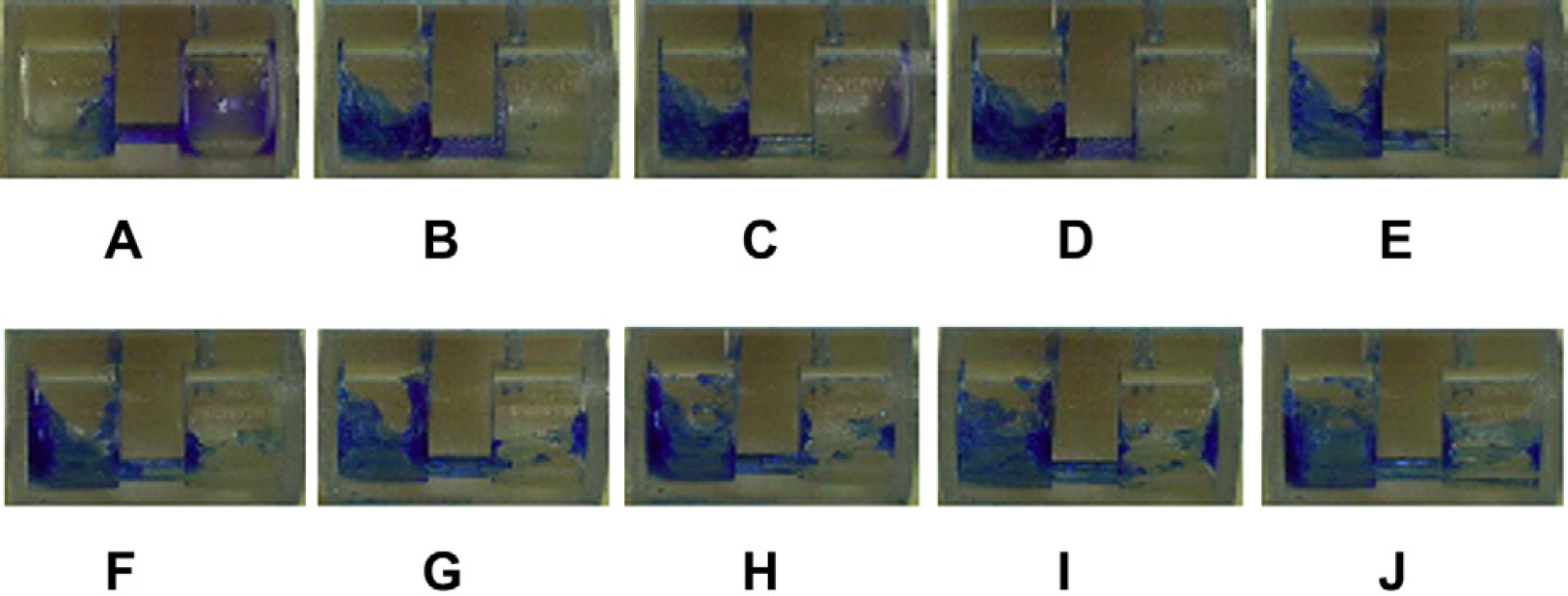
The mixing process: (A) monoolein and dyed water are dispensed in the left and right compartments, respectively, (B) the first mixing (centrifugation: from right to left), (C) the second mixing (centrifugation: from left to right), (D) the third mixing (centrifugation: from right to left), (E) the forth mixing (centrifugation: from left to right), (F) the fifth mixing (centrifugation: from right to left), (G) the sixth mixing (centrifugation: from left to right), (h) the seventh mixing (centrifugation: from right to left), (I) the eighth mixing (centrifugation: from left to right), and the ninth mixing (centrifugation: from right to left).
In the second stage, the mixture of monoolein and water oscillates in the left compartment for mixing as the direction on centrifugation alternates although it cannot flow back to the right compartment, which is shown in Figures 11B#x2014;F. Meanwhile, some remaining water continues to flow back and forth through the microchannel to mix with the mixture in the left compartment through jetting, which is shown in Figure 11C and E. However, the water shown in Figures 11C is less than that in Figures 11E, which means that more and more water has mixed with monoolein, and the volume of the remaining water is getting smaller and smaller until all goes into the mixture.
In the final stage, free water is all exhausted after four TOMs. The viscosity of the mixture becomes so low that the mixture can be shaken in the left compartment under the alternated centrifugation as shown in Figure Figures 11F-I. Although a little mixture travels to the right compartment under centrifugation as shown in Figure Figures 11G, most of them can flow back to the left compartment in the next mixing as shown in Figures 11H. In this way, the mixture repeats to shake in the left compartment until the homogeneous mixture is achieved. The question is how many TOMs should be used to achieve the desired mixing, which can be determined by the image analysis of the mixture, while theoretically it is not possible to determine an optimal TOM.
We used image intensity histogram as an effective approach to judge the homogeneity of the mixing. 38 To obtain the intensity histogram, the photos taken at the end of TOM = 4, 6, 7, 8, 9, and 10 are used and converted into an 8-bit grayscale bitmap (0–255). Figures 12 shows the intensity histogram of each of the sample images. At TOM = 4, 6, and 7, the histograms still have a wide distribution, whereas at TOM = 8, 9, and 10, the distributions become narrower and stable. The corresponding standard deviations of all the TOMs are shown in Figures 13, which shows that the standard deviation becomes stable after TOM = 8, which means 8 is the optimal number of TOM.
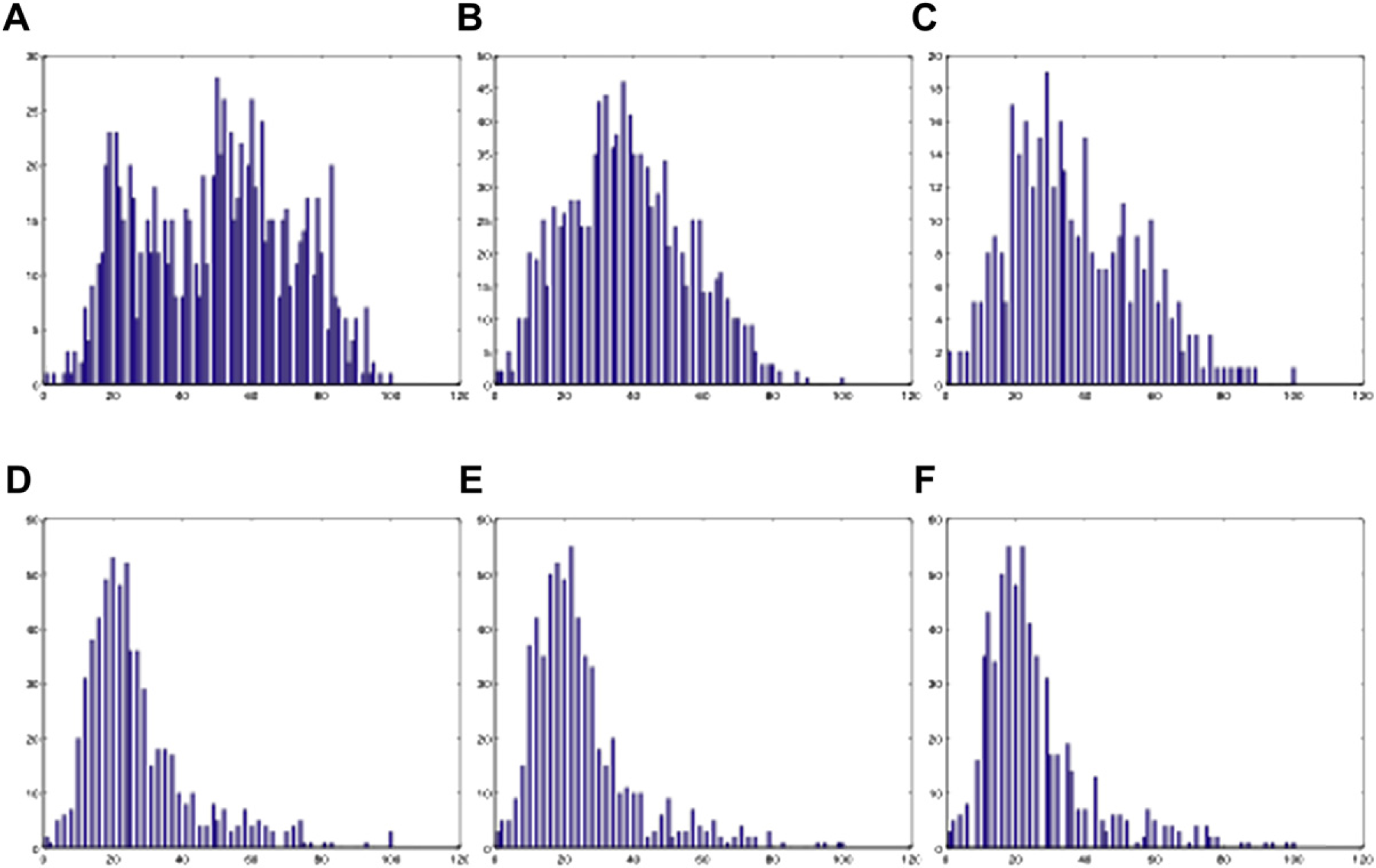
The 2D histograms at different TOMs with water: (A) TOM = 4, (B) TOM = 6, (C) TOM = 7, (D) TOM = 8, (E) TOM = 9, (F) TOM = 10. The unit of the horizontal axis is pixel intensity, and that of the vertical axis is the number of pixels.
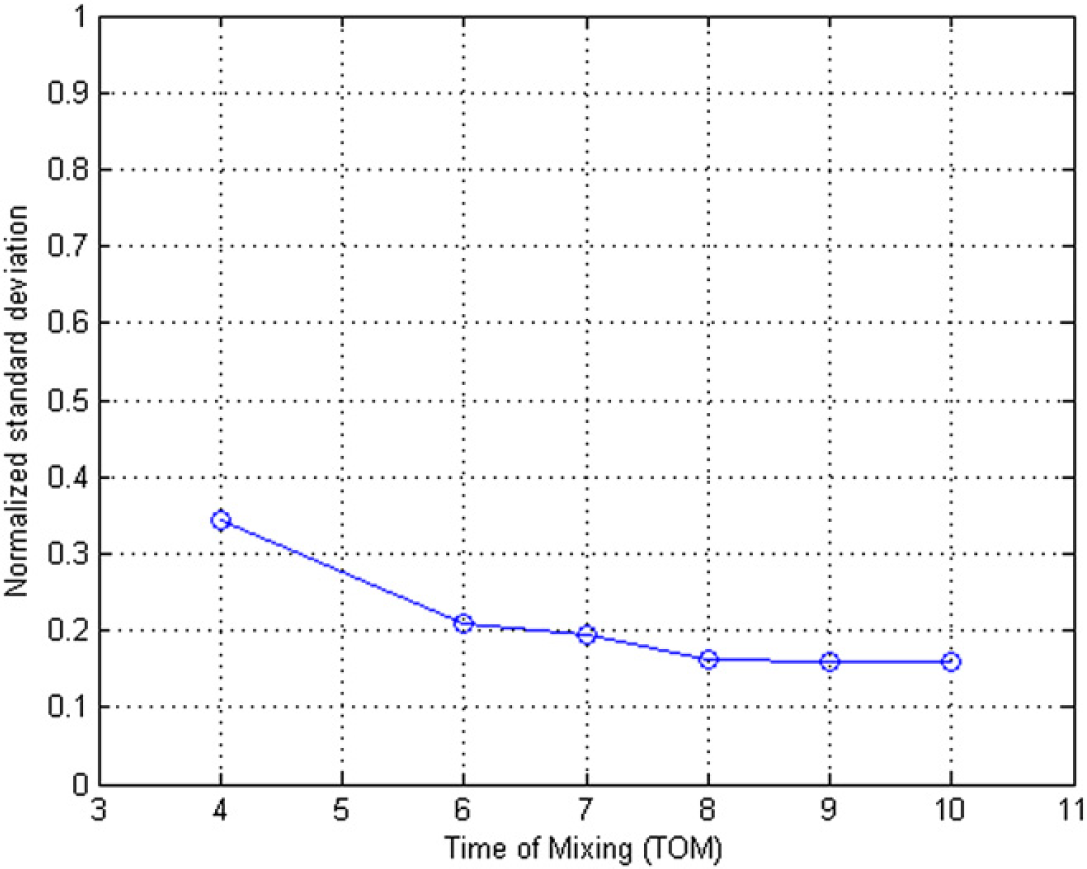
The corresponding 2D histograms standard deviations at different TOMS.
Experiments
In this section, we further test the optimal TOMs by examining the cubic phase of the mixed biosamples. Fundamentally, the mixture has to be homogeneous such that the cubic-Pn3m phase is uniformly formed. The goal is to reach the homogeneity by just enough TOMs. If too few, the desired cubic phase cannot be formed while too many, extra time, and energy will be a waste.
The method we use is to examine multiple samples taken from different parts of the mixture using X-ray diffraction because for a particular cubic phase there is a corresponding pattern of diffraction. If the mixture is homogeneous, every sample from the mixture should produce the same diffraction pattern; otherwise, the diffraction patterns between the samples may be different. According to the equilibrium temperature-composition phase diagram, 1,39 Pn3m can form after mixing of three parts monoolein with two parts water in homogeneity at 20 °C. For Pn3m, the pattern of diffraction is available as reported in ref. 35.
Experimental Preparation and Method


Experimental Results
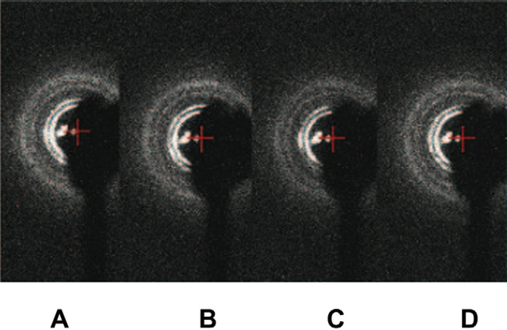
When the TOM is five, the four samples taken from the mixture are different. From the diffraction patterns, one can find four phases including water, Lc, La, and Ia3d as shown in Figures 14. The latter three phases reflect that the water percentage in monoolein is less than 40%, which is not surprising because the water has not all been homogeneously mixed into the monoolein. Figures 15 shows different phases for another four samples taken from the mixture at TOM = 6 including Lα, Lα+Ia3d, and Ia3d, which means that water percentage in monoolein is still less than 40%. Figures 16 shows different phases for four samples taken from the mixture at TOM = 7 including water, Ia3d, Ia3d+Pn3m, and Pn3m. One can see that after more TOM, Pn3m starts to form, but the biosamples are still not evenly mixed. Water still exists that has not been evenly and completely mixed into monoolein such that Ia3d coexists with Pn3m. Figures 17 shows the result of the four samples after TOM = 8. Again the four samples are randomly taken from the mixture in the microcapsule, and the X-ray diffraction shows the patterns of Pn3m for all the four samples. This proves that mixing has been evenly achieved. Table 1 shows the X-ray diffraction data of the three mixing results as shown in Figures 16D, Figures 17A and Figures 17B corresponding to a primitive cubic lattice with the unit cell axis. One can see that the spacing of the set of lattice planes (d), the reflection strength of lattice planes (intensity), the Miller indices (hkl), and the lattice spacing (a 0 ) are close to each other indicating the formation of the Pn3m cubic phase, whereas those for Figures 17A and B are almost identical. Because Figures 17A and Figures 17B are samples from the same mixing result, the data reveal a very even mixing after TOM = 8. Figures 18 shows the low-angle X-ray diffraction profile at TOM = 8.
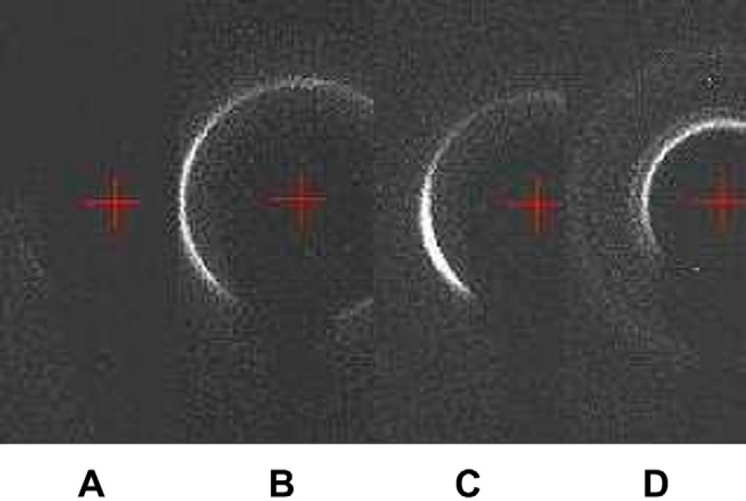
Low-angle X-ray diffraction patterns of the four samples taken from the mixed cubic phase in the microcapsule after five TOMs: (A) water, (B) Lc, (C) Lα, and (D) Ia3d.
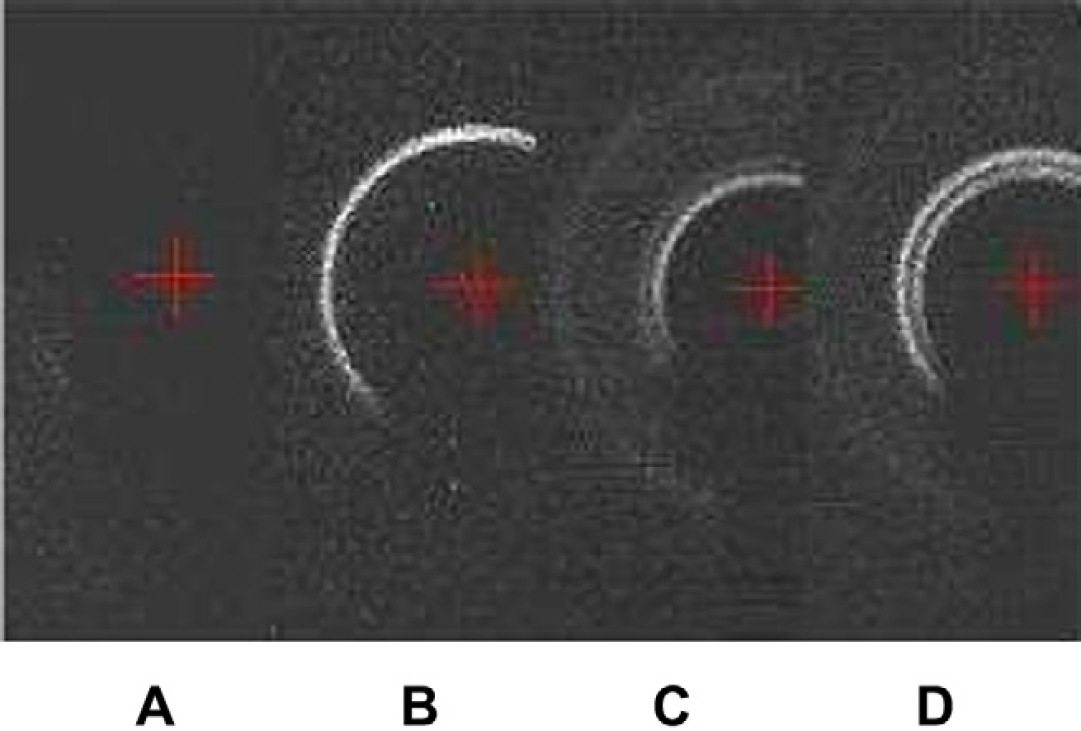
Low-angle X-ray diffraction patterns of the four samples taken from the mixed cubic phase in the microcapsule after six TOMs: (A) water, (B) Lα, (C) Ia3d+Lα, and (D) Ia3d.
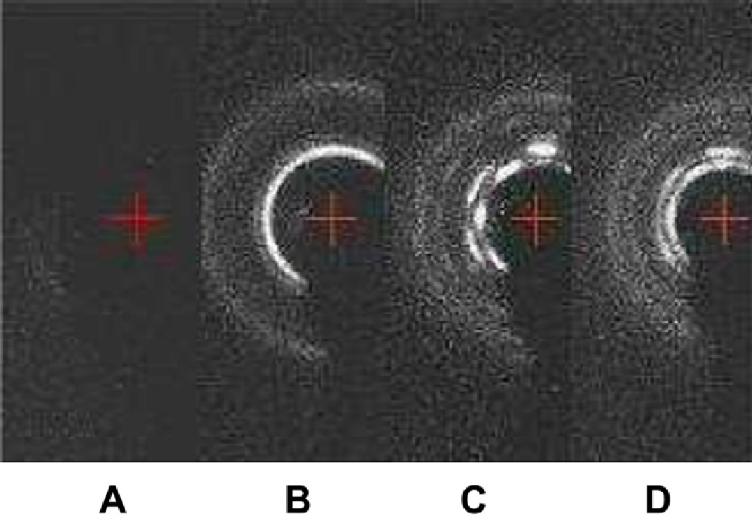
Low-angle X-ray diffraction patterns of the four samples taken from the mixed cubic phase in the microcapsule after seven TOMs: (A) water, (B) Ia3d, (C) Ia3d+Pn3m, and (D) Pn3m.
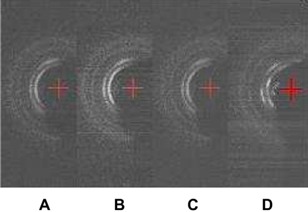
Low-angle X-ray diffraction patterns of the four samples taken from the mixed cubic phase in the microcapsule after eight TOMs. All shows Pn3m.
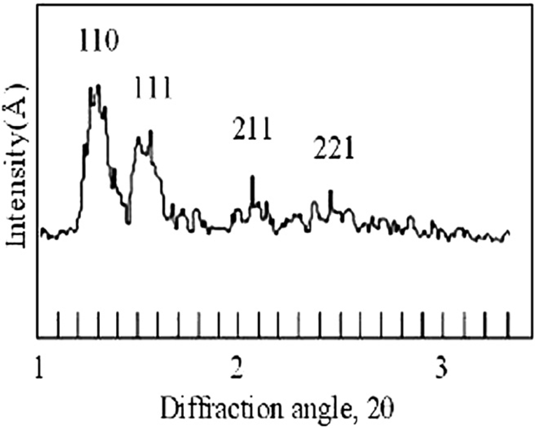
Low-angle X-ray diffraction profile obtained from monoolein and water mixing at TOM = 8.
X-ray diffraction Data
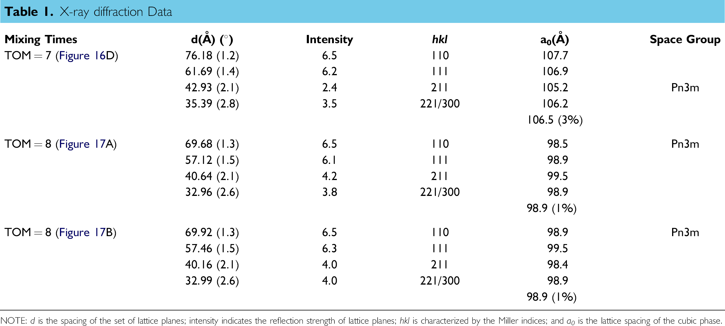
NOTE: d is the spacing of the set of lattice planes; intensity indicates the reflection strength of lattice planes; hkl is characterized by the Miller indices; and a 0 is the lattice spacing of the cubic phase.
Low-angle X-ray diffraction patterns of the four samples taken from the mixed cubic phase with the Rh membrane protein solution in the microcapsule after eight TOMs. All shows Pn3m.
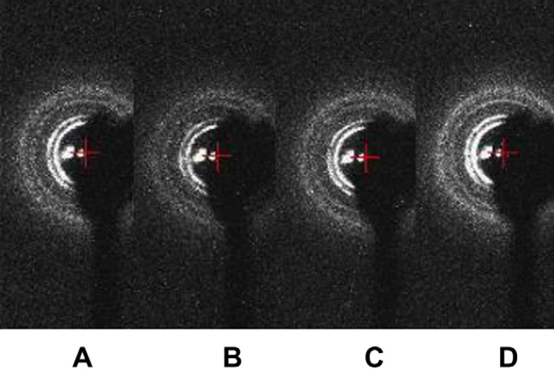
Low-angle X-ray diffraction patterns of the four samples taken from the mixed cubic phase with the Rh membrane protein solution in the microcapsule, which is on the row with alternately changed centrifugal radius after eight TOMs. All shows Pn3m.
X-ray Diffraction Data With Membrane Protein Solution
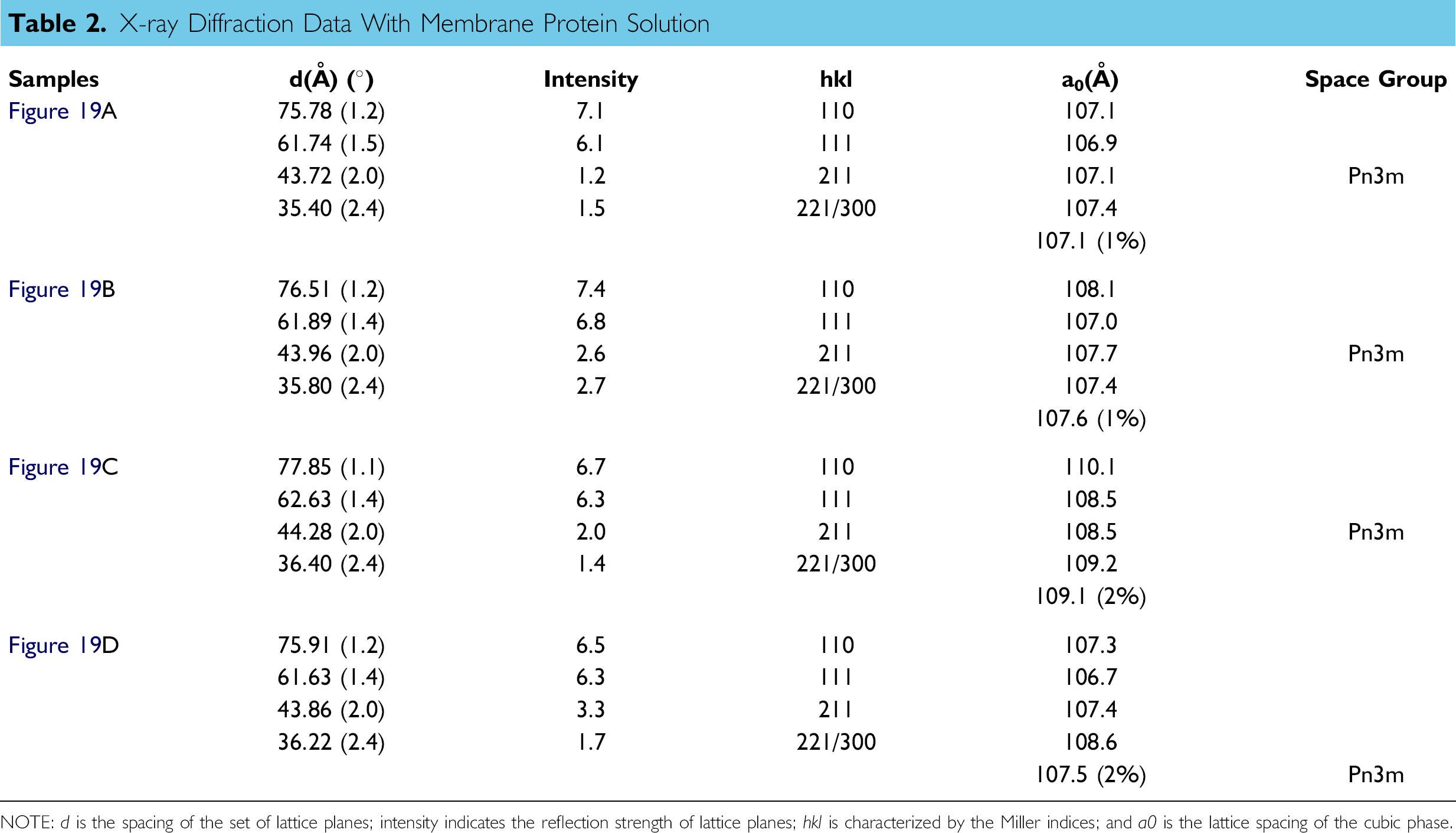
NOTE: d is the spacing of the set of lattice planes; intensity indicates the reflection strength of lattice planes; hkl is characterized by the Miller indices; and a0 is the lattice spacing of the cubic phase.
X-ray Diffraction Data With Membrane Protein Solution
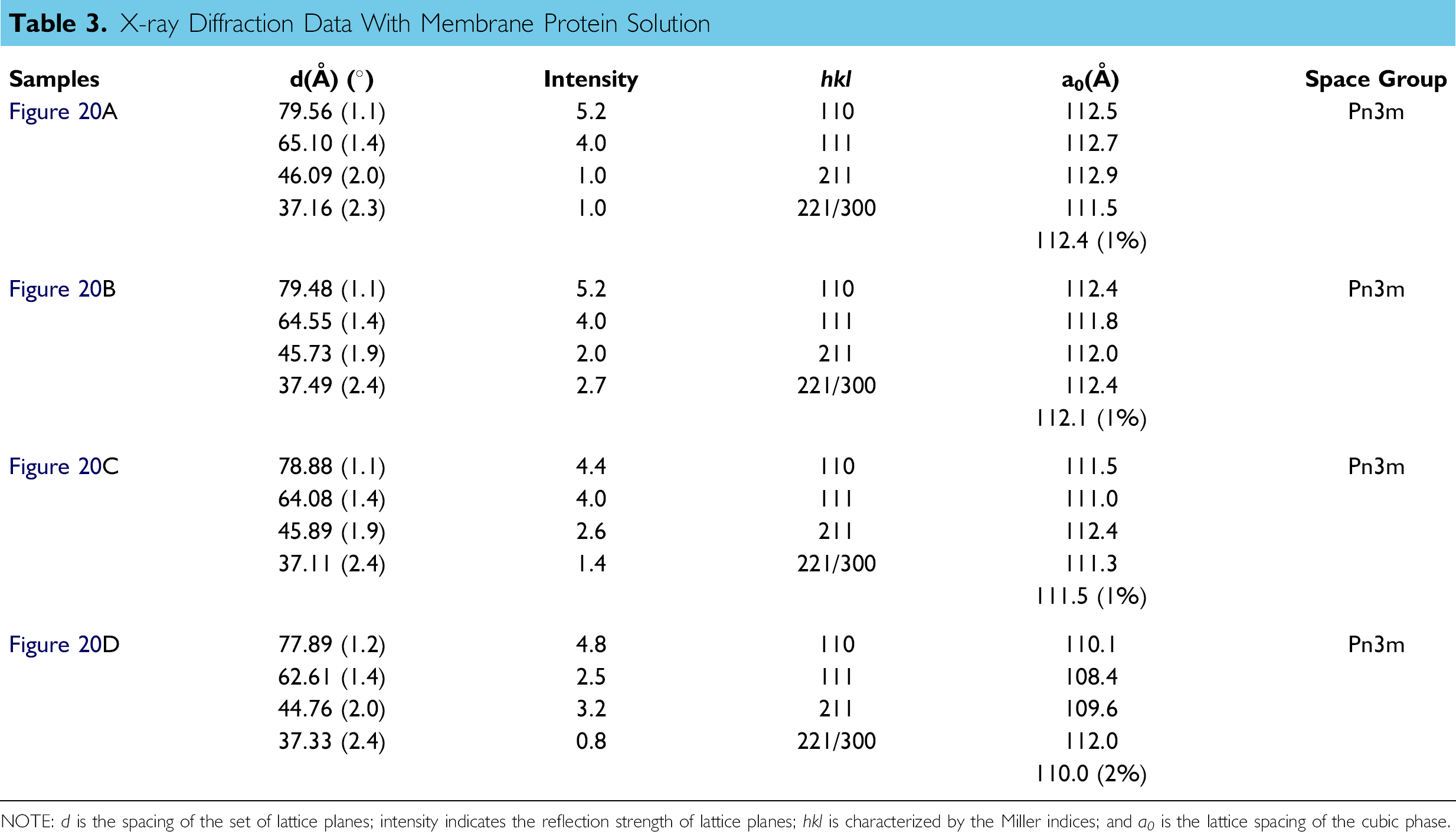
NOTE: d is the spacing of the set of lattice planes; intensity indicates the reflection strength of lattice planes; hkl is characterized by the Miller indices; and a 0 is the lattice spacing of the cubic phase.
The experiment results verify that the proposed method of mixing is effective. The optimal TOM was discussed with image histogram analysis and also verified by experiments. Here, optimality means just enough TOM to reach an even mixing, nothing less or more. As shown in the image standard deviation and experiments, eight is an optimal number for TOM because it will not get job done if less than eight and waste time and energy if more.
Conclusions
In this article, we have presented a mechanism for mixing highly viscous biosamples using a microdevice called microcapsule, which is structured with a microchannel connecting two compartments and centrifugation. We first present the design of a microcapsule for holding and mixing the biosamples in which a microchannel is built. The size of the microcapsule is designed in such a way that it is enough to hold biosamples and suitable for building a microarray plate for the high-throughput purpose. According to the requirement of turbulence flow and effective mixing, the diameter of the microchannel is determined, once the length of the microchannel is selected. To further facilitate microchannel mixing, the flow of viscous materials in the microchannel is studied. A mathematical model that governs the behavior of the flow is developed. To understand microchannel mixing with centrifugation, Reynolds number is derived based on the structure of the microcapsule and the dimension of the microchannel. Then, the mixing process is analyzed according to the Reynolds numbers of water and monoolein, respectively. It is shown that the flow of the water is turbulence. Turbulence flow of the water generates eddies and vortices that smash the monoolein in the other compartment to achieve effective diffusion. As the water continues to diffuse into the monoolein by alternating the direction of centrifugation, the viscosity of the mixture becomes lower and lower. Consequently, shaking of the mixture in one compartment becomes possible, which further improves the effectiveness of the mixing. Experimental results have shown that the invented mixing method is effective for mixing two biosamples with low and high viscosities, respectively. The article has also shown that the optimal TOM can be determined by visual observation method. Finally, this article has been using the cubic phase required in the in meso method as the target of study. The method however can be used to mix viscous biosamples of other kinds at the microliter scale.
Acknowledgment
This work was supported by the National Science Foundation under the grant IIS-0712845.
Competing Interests Statement: The authors certify that they have no relevantfinancial interests in this manuscript.