
Abstract
A highly sensitive biodetection technology using nanomagnetic sensors and magnetic nanoparticles (NPs) was developed. Absorption of magnetic NPs by the hybridized DNA alters the sensor resistance and generated electrical signals that can be directly measured with the off-die or on-die circuitry. Assays with DNA concentration down to sub-10 pM with a dynamic range of three orders of magnitude were demonstrated. The proposed biochip can be applied to other bioreaction detections, for example, protein assay, through different surface modifications.
Introduction
It has been demonstrated that affinity-based sensing, such as hybridization between complementary single-stranded DNA in microarrays or affinity binding of a matched antibody-antigen pair in immunoassays, plays an important role in life sciences, clinical diagnostics, and medical research. However, existing microarray technologies that detect fluorescent emission require a bulky and expensive instrument and may not be suitable for certain applications, for example, point-of-care disease diagnostics. Therefore, smaller, faster, and cheaper devices are highly desired. Biosensor technologies hold great promise to revolutionize the microarray platform because of its high sensitivity, multiplexing capability, and low cost.
Over the past decades we have witnessed a tremendous amount of research activity in the area of biosensors. Fundamental studies in biosensor development involve both biological recognition elements (BREs) and transduction devices. Enzymes, antibodies, and nucleic acids are three main classes of BREs used in biosensor applications, and advances in molecular biology and biochemistry have led to a much better understanding of these BREs.
Physicochemical transducers using different mechanisms, which may be optical, electrochemical, ther-mometric, piezoelectric, or micromechanical,1-5 are drawing a lot of interest. Magnetic biosensors are also under active development and may soon rival established biological detection methods that use surface-bond fluorescent tags.6, 7 Integrating transducer arrays and other laboratory functions on a single chip yields a low-cost system (lab-on-a-chip) that constitutes a promising tool for future biological diagnostics.
Magnetic Biochip Principle
Functionalized magnetic micro- and nanoparticles (NPs) have been studied extensively for biological applications, such as sample purification and cell separation.
8
The cells are first stained with a biotinylated primary antibody or ligand. Subsequently, the cells are magnetically labeled with streptavidin (SA)-coated magnetic beads. Under the magnetic field, the magnetic labeled cells (target cells) will be retained in the column, whereas the unlabeled cells will just flow through. Recently, using the magnetic particles as labels for DNA or protein detection has attracted considerable attention. The principle of the magnetic DNA detection scheme is illustrated in Figure 1.
Principle of using magnetic biosensor and magnetic nanotags. (A) Immobilization of single-stranded DNA with known sequence. (B) Hybridization of complementary target DNA. (C) Capture of magnetic NPs via streptavidin-biotin binding. The resistance of the sensor is altered by the magnetic field generated from attached NPs.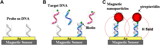
Single-stranded DNA receptors are immobilized on the surface of magnetic sensors. Oligonucleotides of unknown sequence are selectively captured by complementary probes. SA-coated magnetic NPs are then introduced and bind to the biotin of the hybridized DNA. Finally, magnetic field disturbances because of the NPs are sensed by magnetic sensors. The use of magnetic labeling provides the advantages of negligible interference from the sample background, long-term stability (no photobleaching, such as in fluorescent labeling), and easy miniaturization for large-scale molecular detection. There are many magnetic devices that can be used to detect the stray field from magnetic particles. For example, superconducting quantum interference devices (SQUID) have been demonstrated in a highly sensitive immunoassay application.9, 10 However, the high cost of the instrument and the difficulty of miniaturization limit the practicability of SQUID biosensors. Silicon Hall sensors 11 and micro-Hall sensors12, 13 can be fabricated as high-density arrays by the standard complementary metal oxide semiconductor (CMOS) process and are used to detect a single magnetic microsphere. Nevertheless, the assay measurements using Hall sensors are exiguous and their applicability has to be further examined.
GMR Biosensor
Giant magnetoresistive Schematic illustration of the GMR mechanism (top) and the equivalent circuits (bottom) of magnetic multilayers with antiferro-magnetic (right) and ferromagnetic (left) coupling. The carriers with spin parallel to the magnetization in ferromagnetic coupling have a longer mean free path.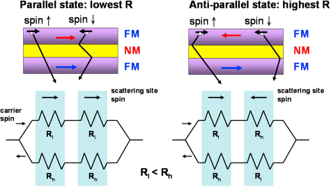
The best known structure to observe GMR effect is the spin valve structure. 16 In a spin valve, two magnetic layers are separated by a nonmagnetic conducting spacer, such as Cu, and the resistance of this sandwich structure depends on the relative orientation of the magnetization in the two magnetic layers. The direction of the magnetization in one of the layers (pinned layer) is always pinned by an exchange bias interaction with an antiferromagnetic or ferromagnetic layer, such as FeMn or IrMn. On the other hand, the magnetization in the second layer (free layer) can rotate freely when the magnetic field changes, which corresponds to a change in resistance. Because of its high sensitivity to small fields, the spin valve is now being considered as a promising candidate for biosensing applications.
Materials and methods
Sensor Design
The configuration of a rectangular spin valve sensor is shown in Figure 3. The pinned magnetization Schematic illustration of a spin valve sensor with a magnetic NP bound to the surface. The magnetic field configuration during the magnetic biodetection is also shown.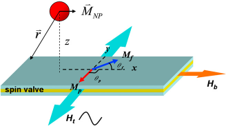

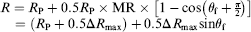
Absorption of magnetic NPs will change sinθf, thus changing the resistance of the sensor. To achieve the magnetization configuration in Figure 3 when we fabricate the spin valve sensor, the spin valve stack is deposited under the magnetic field in the transverse direction. Although both uniaxial anisotropics in the free layer and the pinned layer have the same preferred orientation for the full films, we can introduce a shape anisotropy to align the free layer magnetization in the longitudinal direction by patterning the spin valve sensor in a long strip. Furthermore, we can apply a direct current (dc) bias field along the longitudinal direction during the experiment to help orientate the free layer magnetization. This dc magnetic field also stabilizes the free layer and reduces the Barkhausen noise caused by multidomain nucleation and motion.
The biological active area is defined as the region where the actual molecular binding occurs. Using a standard photolithography technique, we can pattern an active area for probe oligonucleotides or antigens immobilization via cova-lent interaction. Despite some nonspecific absorption, most of the particles are mainly captured within this region. Li 17 first reported the signal dependence on the location of this region in. It was found that the signal from the particle on the either side of the sensor has an opposite polarity to the one on the sensor. The micromagnetic simulation can be used to address this point.
For the superparamagnetic nanoparticle, the Langevin function can be used to calculate the moment of the particle (μNP), which is

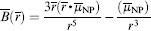
This value can be used in micromagnetic simulation and we can obtain the magnetization change of the free layer (Δsinθf) because of this field. For all simulations in this section, we will consider Δsinθf caused by a 10-nm diameter cobalt nanoparticle (μs = 7.54e-16 emu/particle). Figure 4 shows the simulation results of Δsinθf when we move the particle from the outside of the sensor to the center of the sensor. The sensor was assumed to be 2 mm in length and 300 nm in width for all three cases. For case 1, the distance between the particle and the sensor surface ( sinθf as a function of the position of a 10-nm Co particle.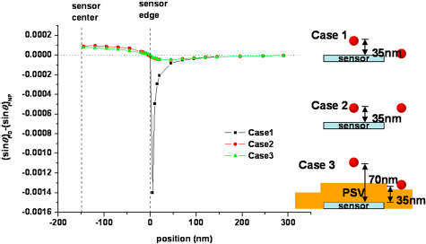
Surface Modification
Surface modification for DNA immobilization and hybridization has to satisfy two requirements. First, it should provide high specificity and clean background. Second, the surface modification process has to be compatible with the devices on the chip; thus it causes no damages to them. The detailed description of surface modification steps used for the discrete-type magnetic biochip can be found in Ref. 19 and will be briefly explained in this section.
The fabricated magnetic biochip having SiO2 passivation layer is first coated with polyallylamine (polyamine) and baked at 170
Magnetic Label
The magnetic NP for biodetection should at least satisfy these requirements. They should be superparamagnetic to prevent particle agglomeration. They should also show low saturation fields to minimize the required magnetic field during the measurement. Certainly, they have to be stable and biocompatible and provide low nonspecific binding, which is important for high signal-to-noise ratio. In all of our experiments, we used commercially available MACS beads (Miltenyi Biotec Gmbh, Germany) as magnetic labels. From the M-H measurement shown in Figure 5A, MACS particles exhibit a superparamagnetic characteristic, and the measured curve match well with Langevin function with a particle radius of 6A (magnetic core radius). The curve also shows a low saturation field; hence around 50% of the saturation moment can be obtained by applying a 100-Oe magnetic field. Single MACS particle has multiple iron oxide cores embedded in a polymer matrix, as can be seen in the Transmission Electron Microscope image (Fig. 5B). The hy-drodynamic size is ∼100 nm in diameter from the dynamic light scattering measurement.
MACS beads properties. (A) M-H measurement result which is fitted with Langevin function. Minot loop is shown as an inset. (B) Transmission Electron Microscope image.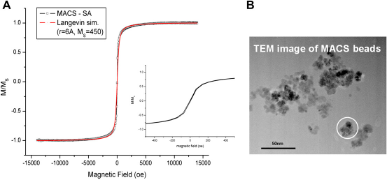
Measured Results and Discussion
To demonstrate the working biochemistry, we performed a full assay with different target DNA concentrations on dummy chips and inspected the particle coverage with SEM. Figure 6 shows the particle area coverage versus target DNA concentration for polyamine surfaces. Below certain coverage (∼11%), DNA diffusion limits the particle binding; therefore the coverage is proportional to the target DNA concentration. However, when the density of surface binding sites increases, the steric effect between particles starts to dominate the particle binding and the curve shows saturation. Here, we also include the similar experimental results using another popular surface modification method via thiol group and gold binding. It is interesting to note that two surface modification methods have different behaviors that might be because of very different probe DNA densities on the surface.
Particle area coverage versus target DNA concentrations for both polyallylamine (circle) and thio-Au (square) surface modification methods.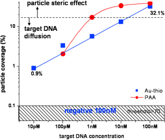
For all the following experiments, we supplied a 15μA dc plus a 10μA (peak) 1 KHz sinusoidal current to the spin valve sensors. The biasing current level was carefully selected so that the peak voltage of the sensor was below 1 V to prevent a passivation breakdown during the real-time measurement. A 208 Hz in-plane magnetic field with the amplitude of 85 Oe (rms) was applied, and we recorded the tone at 1208 Hz from the double modulation. 20
Our biochip used an indirect labeling technique. After hybridization was completed, we then placed the magnetic biochip into the test setup and recorded the signal change because of the magnetic nanoparticle absorption on the sensor surface. Real-time measurement results from sensors with different target DNA concentrations and their corresponding SEM images. The onset of the curves corresponds to injection of magnetic NP solution. The 10-pM curve did not have a rinse, resulting in salts left on the sensors.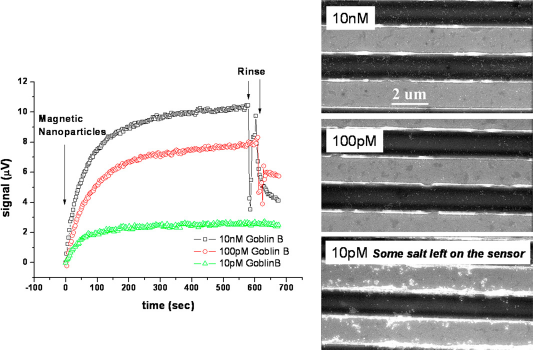
Conclusion
Footnotes
Acknowledgements