
Abstract
As a result of a rapidly increasing demand for accurate, cost-effective, and highly flexible multiplexed assay systems, the annual market for multiplex assays is currently billions of dollars and is expected to continue to grow exponentially. Presently, there exist two broad classes of surface-based multiplex platforms—those using fixed planar surfaces (fixed arrays) and those that are particle-based (liquid arrays). We present here a description of an “Arrayable Liquid Array” platform, based on Encoded Sortable Particle (ESP) technology that combines many of the advantages of fixed and liquid arrays. ESPs have significant advantages in throughput, scalability, mixing efficiency, and flexibility over existing liquid array platforms while also incorporating the detection and manufacturing benefits of fixed arrays.
Introduction
Multiplex Assay Technologies
In the bioassay space, there are two surface-based multiplex array platform types—“fixed” and “liquid.” 1 -3 Fixed array platforms are those on which assays are carried out on a shared, typically two-dimensional, matrix where assay identification is made by coordinate location. DNA microarrays (e.g., Affymetrix chips, Santa Clara, CA) are the most commonly used fixed array product. Liquid array platforms are those on which each assay is carried out on a separate support, such as a particle or bead, with the separate supports identified by a unique characteristic (e.g., code). Perhaps, the most widely used liquid array platforms are based on the use of fluorescently labeled beads (e.g., Luminex xMAP bead system) that can be decoded by flow cytometry-based readers. These two types of multiplex assay platforms occupy complementary portions of the multiplex landscape: liquid arrays dominating the under 500-plex space and fixed arrays dominating the over 1000-plex space. This division exists substantially due to economic considerations. Fixed arrays, or microarrays, are manufactured as a unit with a significant portion of the cost of the microarray inherent in the manufacturing process used to produce the microarray; consequently, the more assays per microarray (i.e., the greater the plex size) the lower the cost per data point. For liquid arrays, individual types of particles are generally produced in separate batch manufacturing processes with the result that the cost per data point remains relatively fixed independent of plex size. The economic crossover point—the point at which it becomes no longer cost-effective to increase the plex size of a liquid array, or decrease the plex size of a fixed array—typically occurs around 500- to 1000-plex, depending on the specific fixed and liquid arrays being compared.
David M. Rothwarf, Ph.D.

Liquid Array Advantages
Liquid array platforms offer a variety of advantages over fixed arrays. Most specifically, because each assay support comprises a discrete substrate, it can be generated in a separate reaction milieu; thereby allowing each assay in a multiplex analysis to be performed on a substrate that has been optimized for the specific assay. Not only can different particles in a common multiplex assay contain different surface chemistries for attachment, but different particles can also be made out of different materials, stored in individually optimized conditions and combined immediately prior to use. Additionally, liquid arrays are infinitely configurable. Because they are comprised of separate, discrete elements they can be reconfigured after manufacture (e.g., a multiplex assay can be augmented by adding additional particles), whereas, a fixed array, once manufactured, cannot be easily altered. For the end-user striving for a customized product, liquid arrays equate to simple mixing of the desired activated particles, while fixed arrays require a new manufacturing run.
Ideally, liquid arrays are easier to use and more adaptable to sample size and concentration. This is a consequence of the liquid array being more compact. Whereas fixed array assays require solution to be spread over a large flat surface, presenting difficulties in ensuring uniform temperature, adequate mixing and that the sample does not dry down during incubation, liquid array assays can be performed in small tubes or wells in a homogeneous solution and with much smaller volumes. Liquid arrays also offer advantages in the attachment of capture molecules (e.g., oligonucleotides or antibodies) because reactions can be carried out under a much wider range of solution conditions than available in the manufacture of fixed arrays. In fixed arrays, the volume of reagent delivered, its concentration, and its surface tension relative to the array surface are often dictated by the size of the spot and density distribution of the assay surface area.
Many of the advantages liquid arrays have over fixed arrays are negated in the case of DNA hybridization assays due to the unique properties of oligonucleotides, which have uniform and predictable chemistry, exceptional stability, and can be synthesized at low cost. These properties have allowed DNA arrays to be manufactured in a variety of ways, 4,5 including being “printed” (e.g., using Agilent ink jet technology, Santa Clara, CA), or synthesized in parallel directly on the array using photolithography (e.g., Affymetrix) or microelectrodes (e.g., Combimatrix, Mukilteo, WA).
Fixed Array Advantages
Fixed arrays have advantages over conventional particle-based liquid arrays in the areas of manufacturing efficiency, data collection, and spatial identification of assay location. Fixed arrays are manufactured as a unit in a single manufacturing process, whereas bead-based liquid arrays require separate manufacturing runs for each batch of beads. At high plex, this has significant financial consequences. For example, a 100,000-plex microarray is produced in a single manufacturing process while a 100,000-plex bead-based liquid array requires 100,000 manufacturing processes (one for each different type of bead). In the case of the bead-based assay, this would represent a significant investment in inventory, as beads are made in large batches. It would also make any design change prohibitively expensive. Although smaller batches of beads can be produced, as batch size decreases the cost per assay increases due to fixed costs, and because the bead-based platforms are already significantly more expensive on a per assay basis than microarrays at plex sizes well below 100,000, the situation is exacerbated as the plex size increases.
Analysis of fixed arrays is generally easier and less expensive than analysis of liquid arrays as a consequence of the assay sites being fixed in space, thus allowing optimal orientation of the assay areas with respect to the detection elements (e.g., optics, laser, etc). The relatively static position of assay site and detector also allows extended data acquisition times for fixed arrays, something that is difficult to do with rapidly flowing particles. And, unlike particles which can be lost during processing, the analysis areas of fixed arrays remain attached to the support throughout the process. These factors result in fixed arrays requiring lower redundancy than particle-based assays, especially those using flow-based detectors.
A third advantage of fixed arrays is that because the assay locations are identified by their spatial location they can hold a virtually unlimited number of assays (i.e., infinite-plex). By contrast, liquid arrays require that individual particles are encoded. The ideal liquid array will have an unlimited number of codes, the coding will be robust (error checking and preferably error correction), be rapidly decodable, occupy minimal space, not interfere with the assay, and be inexpensive to implement. In practice, such coding has not materialized despite a considerable number of different approaches having been used. Such methods include the use of fluorescent elements, chemical tags, nanocrystals, radio frequency tags, particles with unique infrared, raman, or diffractive properties, and particles with holes or notches (these and other approaches have been reviewed elsewhere). 3,6 However, thus far, only two particle-encoding technologies have achieved commercial success in the multiplex assay space. The first of these approaches uses fluorescently labeled beads (e.g., Luminex xMAP Technology, Austin, TX) that are encoded by varying the amounts, and thereby intensities, of two or more fluorescent dyes located within the particle. Although the codes are rapidly decodable and occupy minimal space, increasing plex size requires increasing the number of dyes and/or the discrimination between levels of intensity, which becomes progressively more difficult and expensive as the coding space increases. In addition, the coding method, because it is fluorescence-based, has the potential to interfere with the fluorescence-based assay signal. The other successful commercial liquid array platform uses 1-D bar codes that rely on spatially resolved features (e.g., Illumina's VeraCode technology, San Diego, CA). Although this provides the option of a much larger coding space, as well as error checking, the coding method requires more space, which necessitates either larger particles or decoding devices with greater spatial discrimination.
Encoded Sortable Particles
Encoded Sortable Particles (ESPs) are optically encoded microfabricated particles that can be manipulated using magnetic force. A typical ESP (Fig. 1) has a top and bottom layer made of silicon dioxide and a recessed well (bioassay area) that can be specifically and restrictively modified to attach suitable molecules for assays (e.g., DNA, protein, small molecule). These outer silicon dioxide layers completely encapsulate two middle layers: a magnetic layer and an encoding layer. ESPs are manufactured on commercially available photolithographic equipment and consist of multiple layers of material produced using techniques borrowed from the semiconductor industry. An exemplary process of fabricating ESPs is illustrated in Figure 2 with the ESPs on the wafer being shown in crosse–section and the released ESPs viewed from above. The key fabrication steps are summarized below:
The fabrication process begins with the preparation of a silicon wafer of the type used for semiconductor fabrication. The wafer is cleaned and a sacrificial layer is applied. The sacrificial layer holds the ESPs onto the wafer and is dissolved after production to release the ESPs from the wafer surface. The sacrificial layer in this example is copper.
The bottom layer of the ESP is then deposited on the sacrificial layer. In the ESPs shown here, the bottom layer is composed of silicon dioxide.
The encoding layer composed of titanium is then deposited. This layer is patterned using a photomask.
A magnetic layer composed of CoTaZr is deposited and patterned in the same manner as the titanium encoding layer. (In the crosse–sectional view shown in Fig. 2, the deposition of the magnetic bars would obscure the encoding bars, but in the figure they have been left visible for clarity.)
The top layer of silicon dioxide is deposited.
A recessed well (bioassay area) is patterned on the surface using ion milling and a suitable reactive surface is placed in the well.
The wafer is patterned by ion milling to carve out the individual ESPs.
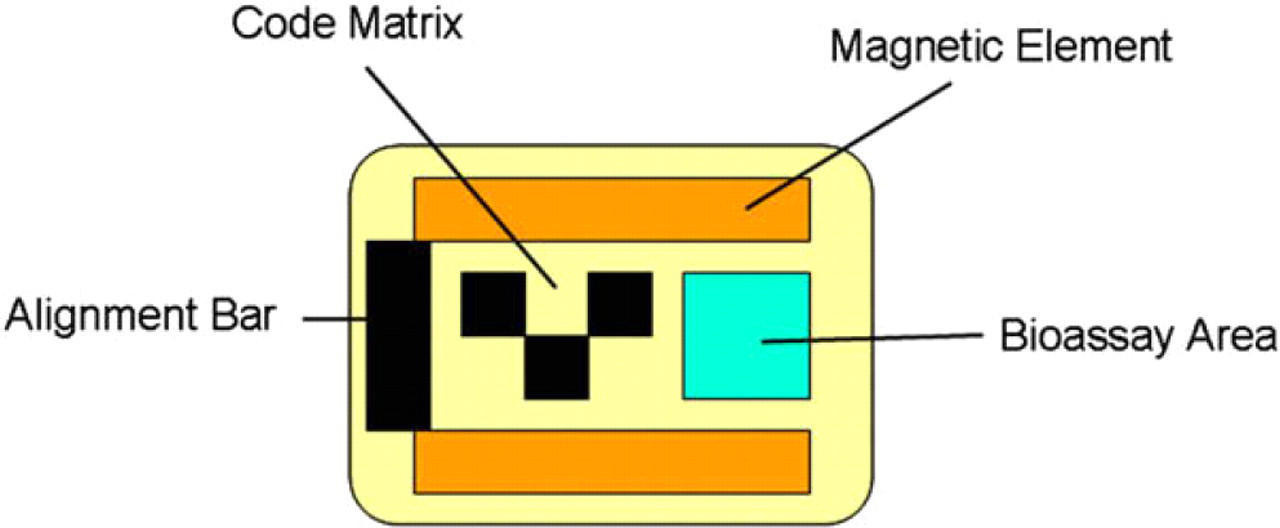
Representative Encoded Sortable Particle of 60 × 75 × 3 μM in dimension with 3 × 2 coding matrix, magnetic bars, and recessed bioassay area.
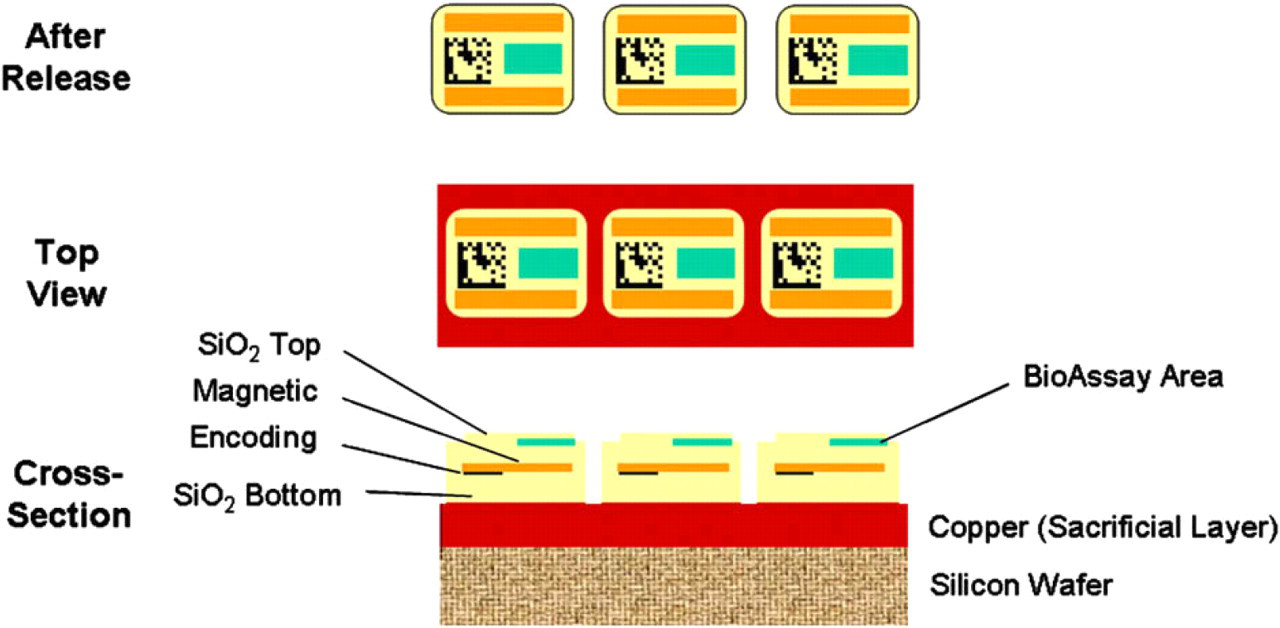
Structure and fabrication of Encoded Sortable Particles (ESPs). Three views of ESPs. Cross-sectional view depicts the layers of ESPs attached to a wafer after photolithographic production. The vertical axis in this cross-sectional view is enlarged ∼ 20-fold for clarity because ESPs are relatively thin with respect to their length and width. Top view represents ESPs still attached to the silicon wafer via the sacrificial copper layer. After release represents free-floating ESPs that have been released from the wafer by dissolution of the sacrificial copper layer with nitric acid. ESPs represented in this depiction are 60 × 75 × 3 μM.
Any pattern that can be produced on a photolithographic mask (i.e., any image that can be represented in a digital form) and any material that can form a thin film can be incorporated into an ESP. These thin films can be produced by a variety of processes including sputtering, chemical vapor deposition, electron beam deposition, thermal deposition, and plating. Consequently, an ESP can comprise a wide variety of features and is completely customizable.
If desired, every ESP location on a wafer can contain a different ESP design, although typically ESPs are made in groups of codes, with each code contained within a fixed region (die) of the wafer, and with thousands to millions of ESPs representing each code within each die. Figure 3 shows an example of 60 × 75 × 3 μM ESPs produced on a 10-cm diameter silicon wafer with 60 1 × 1 cm dies, each die containing ESPs with a specific code. The wafer is diced using dicing marks incorporated into the photolithographic design. The dicing streets are clearly visible in Figure 3 (left). Figure 3 (center) shows an individual die cut from the wafer. Figure 3 (right) shows a 160× magnification of a region of that die. Each die in this example contains over 10,000 ESPs.
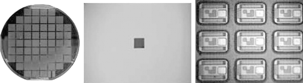
Left: Finished 10 cm diameter wafer with individual dies demarcated by dicing streets. Each die represents a specific coding group and contains over 10,000 Encoded Sortable Particles that are 65 × 70 × 3 μM. Center: An individual 1 cm square die cut from wafer and ready to be treated with nitric acid to dissolve the copper sacrificial layer to release the ESPs from the die into solution. Right: 160× Magnification of ESPs on the die before release.
Because of the nature of the manufacturing process, decreasing the size of each ESP does not significantly increase the cost per wafer; hence, decreasing the size of the ESPs proportionally reduces the cost per ESP. We are currently optimizing production of ESPs that are an order of magnitude smaller than those shown in Figure 3 with the goal of producing ESPs each with a volume less than that of a 6-μM diameter bead.
Magnetic Properties
ESPs contain bars of a Cobalt-Tantalum-Zirconium alloy (CoTaZr; 92:4:4). 7 The strong magnetic properties of CoTaZr result in ESPs responding thousands of times more strongly to magnetic fields than commercially available magnetic beads. This CoTaZr alloy is an isotropic high-permeability ferromagnet: it has no remanence (i.e., magnetic memory) and zero magnetostriction (i.e., no change in dimensions when placed in a magnetic field). Aside from responding much more strongly to magnetic fields than ordinary magnetic beads, ESPs are fundamentally different in the nature of their response. The magnetic bars in the ESP have a preferential axis of magnetization and, within a magnetic field, strive to orient their long axis in the direction of the field (Fig. 4). Hence, in addition to sharing the benefits of magnetic beads (e.g., ease of handling, washing, processing) the movement and arrangement of ESPs can be controlled.
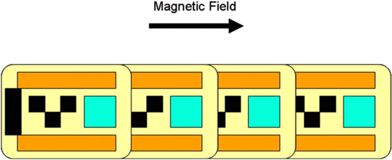
The magnetic bars (orange) in Encoded Sortable Particles (ESPs) have a long axis. In the presence of a magnetic field, ESPs align themselves in the direction of the magnetic field and form chains.
Ordered Arraying of ESPs
Because the magnetic bars in ESPs contain a preferential axis of magnetization, ESPs form chains along their preferential axis when exposed to an external magnetic field. Such chains constitute a form of arraying (Fig. 4). Capitalizing on this characteristic, embedding alternating ESPs (or specifically, just their magnetic bars) in a substrate provides a framework (i.e., an arraying chip) where free ESPs form chains with the embedded magnetic bars. ESPs are thereby arrayed on the fixed substrate as shown in Figure 5. The arraying chip substrate can be composed of any solid material; the arraying chip shown was produced on optical quality glass. Similar magnetic bar arraying chips have been used by other researchers to capture magnetic beads. 8,9 However, ESPs, unlike magnetic beads, have a preferential axis of magnetization and generate a magnetic field comparable and complementary to that of the magnetic bars on the arraying chip. Consequently, ESPs are not passively captured by the arraying chip, but are active participants in a highly efficient arraying process. Moreover, by placing the magnetic bars asymmetrically within the ESP (i.e., closer to the bottom than the top) as illustrated in Figure 6, even a greater level of magnetic control can be exerted on the ESPs to direct them to array in a particular orientation (e.g., all face-up or face-down) in an ordered fashion on a planar surface as shown in Figure 7. Consequently, an ESP-based liquid array exhibits properties of both liquid and fixed array platforms; the multiplex assay can be performed in solution and subsequently the ESPs can be arrayed on a 2D surface for analysis, becoming, in effect, an Arrayable Liquid Array platform.
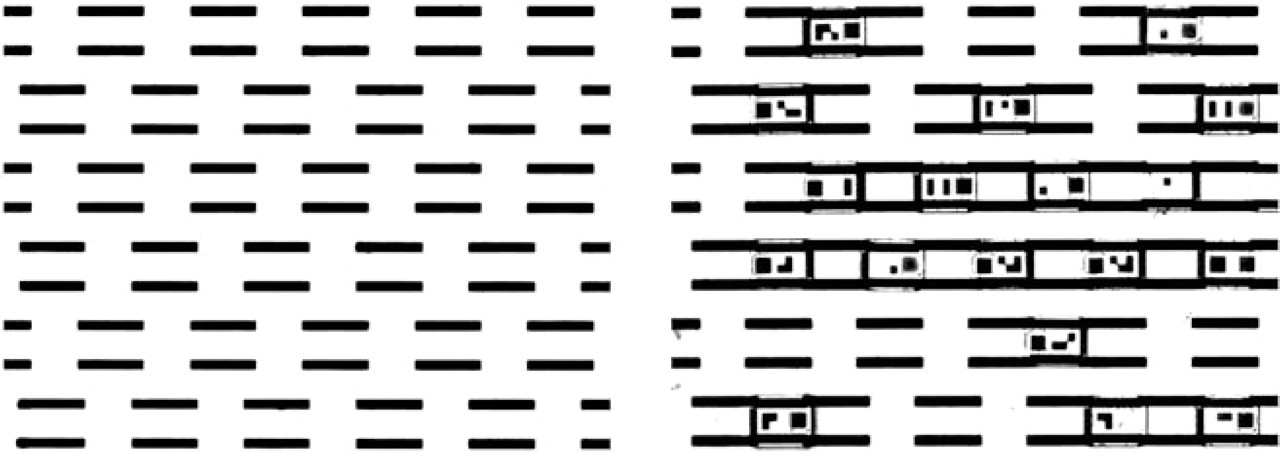
Left: Section of empty arraying chip. The arraying chip is effectively an alternating pattern of magnetic elements of Encoded Sortable Particles (ESPs) embedded in a fixed substrate, in this case, optical quality glass. Right: Section of populated arraying chip. Placing free-floating ESPs on the surface of the arraying chip and applying a magnetic field induces the ESPs to align themselves in a uniform direction and preferentially form magnetic chains with the arraying chip's magnetic elements resulting in the ESPs forming a fixed and ordered array.
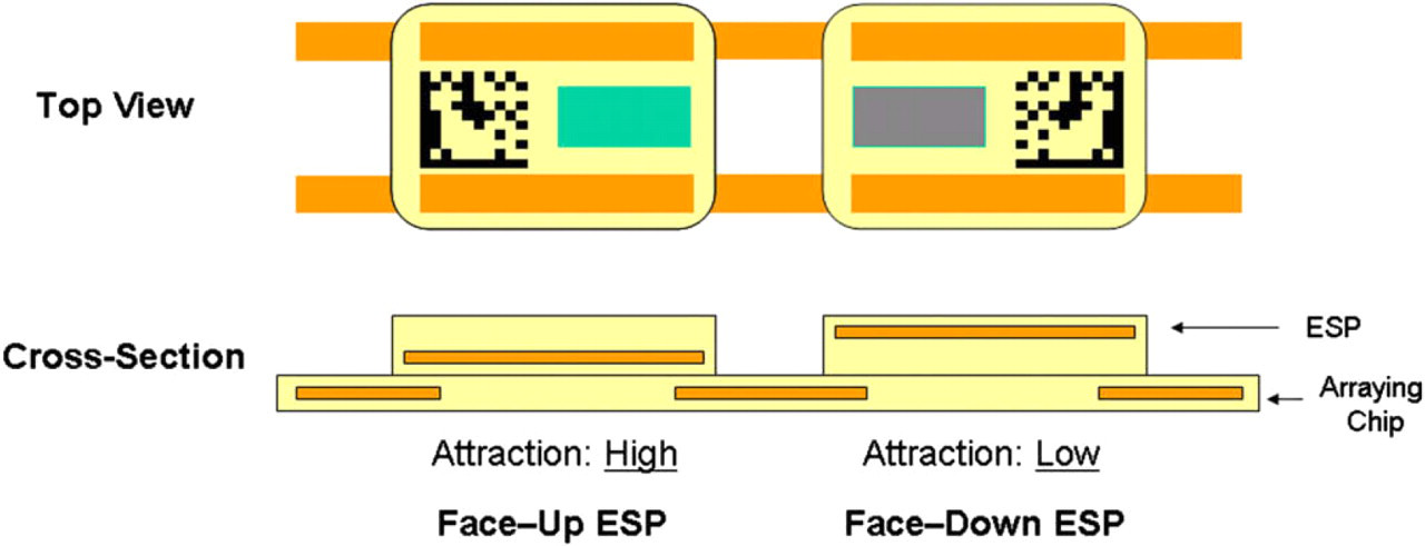
Schematic diagram of Encoded Sortable Particles (ESPs) arrayed on an arraying chip. ESP on the left is arrayed face-up. ESP on the right is arrayed face-down. As shown in the cross-sectional view, the magnetic elements in an ESP are positioned in a biased manner such that when face-up the magnetic elements are closer to the bottom of the ESP than the top. Because their magnetic elements are significantly closer to the magnetic elements in the arraying chip, ESPs that are face-up are more strongly attracted to the arraying chip than those that are face-down. This allows magnetic discrimination between face-up and face-down ESPs, whereby the ESPs can be ordered in an exclusively face-up or face-down orientation using magnetic forces.
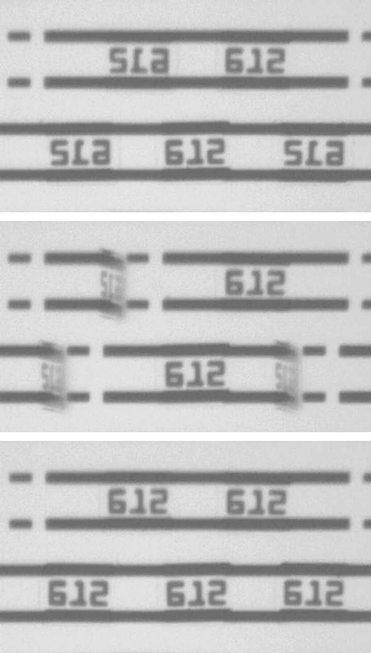
Frame grabs of arrayed Encoded Sortable Particles (ESPs) being arranged with respect to sidedness. Top: ESPs have been arrayed. They are a mixture of face-up and face-down ESPs. When face-up, the numeric code 612 is displayed. Middle: A magnetic field is applied allowing ESPs to be discriminated based on their difference in attraction to the arraying chip as described in Figure 6. Those that are face-down are partially lifted from the surface of the arraying chip. Bottom: After application of an additional magnetic field, the face-down ESPs have flipped in place and are all now face-up.
Encoding
Because ESPs have flat surfaces, they can harbor 2D bar codes that allow large amounts of information to be efficiently compressed into small areas. Although the ESPs shown in Figures 1, 3 –5 contain simple 3 × 2 bar codes, much more complex coding patterns such as the industry-standard DataMatrix, commonly used to encode data up to several hundred digits with extensive error correction capabilities, can be used. The schematic ESPs shown in Figure 2 contain a DataMatrix code that encodes for 1 million codes with error correction.
Advantages of an ESP-Based Liquid Array Platform
Ease of Handling
The magnetic properties of ESPs allow them to be quantitatively recovered after each assay and wash step in a manner similar to that used for magnetic beads. However, unlike conventional magnetic beads, ESPs respond almost instantaneously to an external magnetic field and ESPs can be easily manipulated over distances of several inches with small permanent magnets (e.g., Neodymium-Iron-Boron with no dimension larger than 1/8 in.).
Superior Mixing
ESPs are not conventional magnetic beads. In the presence of an external magnetic field, ESPs orient themselves with the field. One application of this characteristic is mixing—instead of clumping together when placed in a rotating magnetic field (e.g., as found on magnetic stir plates), as do magnetic beads, ESPs behave as miniature magnetic stir bars. If ESPs are placed outside of the central region of the magnetic stir plate, in addition to spinning in a chain-like fashion, they will also separate in response to the changing direction of the magnetic field in a manner analogous to the chaotic motion observed when a stir bar in a beaker is placed on the edge of a magnetic stir plate. As a result of this property, reactions involving ESPs can be carried out with excellent mixing in very small volumes without specialized equipment. By contrast, other liquid array platforms composed of dead-weight particles (i.e., with no internal forces) require significant extra volume to remain in suspension. Besides conserving valuable sample and reagent, this property can be used to maximize reaction rates as stirring has been shown to dramatically increase assay sensitivity in microarray immunoassays. 10 Moreover, magnetic particle-based mixing is particularly efficient. 11
Efficient Data Acquisition
The ability to fix ESPs on a surface in an ordered array allows ESPs to be decoded and their bioassay areas analyzed with equivalent efficiency as that for fixed array platforms. In combination with near quantitative recovery of ESPs during assay procedures, this should allow ESPs to use a redundancy rate comparable to that of fixed arrays.
Conserve Sample
Both the superior mixing properties of ESPs and their ability to be displayed in the manner of a fixed array reduce the number of replicates needed per assay, and, hence, the sample volume required. A third manner in which ESPs conserve sample is by restricting the reactive surface area. Excessively large reaction surface areas adversely affect reaction kinetics as well as decrease assay sensitivity by diluting the assay signal. These effects are generally partially offset by increasing the amount of sample used. In a typical liquid array, the reactive surface of the particle is fixed by the size of the particle, such that the entire surface of the particle is the reactive surface area; thus, particles requiring a certain minimum size for efficient manufacture, encoding, or manipulation result in assays that may be wasteful of sample. The ability to pattern the surface of the ESP to produce a specific bioreactive area decouples the size of the particle from the size of the assay surface, thereby conserving sample.
Coding and Throughput
ESPs use a 2D barcode encoded within the particle. Depending on the coding scheme used, the breadth of encoding for a 2D barcode may be tens to millions or more. Besides the obvious advantages of increasing multiplex levels, increasingly large coding spaces can also be used to increase throughput via encoding of not only the individual assays, but also the individual samples. Whereas encoding of the assay alone requires subsequent serial sample processing, coding of both the sample and the assay allows parallel processing. For example, consider a 1536-well plate assay with a 50-plex assay being performed in each well. If these were performed with 50 codes, one for each assay, processing of the samples in a serial manner would be required to coordinate sample and assay data. However, with a larger coding space the assays for the first well (sample) could be coded as 1–50, for the second as 51 e100, for the third as 101 e150, etcetera, for a total of 76,800 codes per plate. Following the initial sample binding step, ESPs from all 1536 wells could be pooled and processed as a single sample, greatly increasing throughput.
Scalable Manufacturing
ESP manufacture is on a per wafer basis allowing the process to be scaled to the desired plex size. For example, ifESPs are manufactured for a 10,000-plex assay, wafers could contain 10,000 different dies with each die containing a different type of ESP. To meet increased customer demand the number of wafers in a run can be increased, but, unlike other particle-based array platforms, with ESPs there is no need for excess inventory and there is no significant cost difference on a per assay basis between an ESP designed for a 50-plex assay and one designed for a 10,000-plex assay. However, as dies get smaller there will be increasing one complexity with respect to wafer dicing and die sorting due to the production of large numbers of dies/wafer with corresponding lower numbers of ESPs/die. Fortunately, the ESP manufacturing process is based on methods used in the semiconductor industry and there exist well-established processes and equipment for dicing and sorting wafer dies that allow post-manufacture wafer processing to be carried out in a fully automated, high-throughput manner (including optical inspection).
Flexibility/Versatility
Because of their flexible design, ESPs are compatible with virtually any detection or analysis protocol developed for fixed or liquid array multiplex assays. In contrast, the manufacture and design of fluorescently labeled particles are dominated by coding and decoding requirements that cannot be significantly altered. ESPs can be made out of virtually any material, in any shape, and can contain a wide variety of features. In addition, because ESP manufacture involves a multilayer fabrication process, the inclusion of additional features does not significantly impact cost, thereby permitting complex features (e.g., electrical or optical sensors) to be easily incorporated. This adaptability makes ESPs an ideal platform for assay development.
Summary
The ESP-based Arrayable Liquid Array platform is intended to provide broad-based applicability and optimization to virtually any assay type and multiplex level. Production via photolithographic techniques allows not only cost-effective manufacture with virtually unlimited variation, but also direct specification of the size and nature of the bioreactive area within the context of the ESP. The latter is of significant importance in achieving high levels of sensitivity. The magnetic properties of the ESP promote effective mixing, which minimizes sample volume requirements, and enables arraying of ESPs following solution-based assay, thereby optimizing particle recovery, and enhancing efficiency of analysis. The expansive coding space available in conjunction with the aforementioned characteristics makes the ESP-based platform an ideal candidate for high multiplex applications. By merging the advantages of fixed and liquid arrays, the platform is not only intrinsically versatile in construction of the array contents, as well as the array scaffold, but it is also cost-effectively scalable. This platform has the potential to be used in high-throughput discovery and clinical diagnostics, as well as in basic biomedical research.
Acknowledgments
This work was supported in part by grants from the National Human Genome Research Institute.