
Abstract
An elution—extrusion countercurrent chromatography workstation was designed and built in-house for fractionating crude natural product extracts. The engineering efforts of this project included both custom hardware and software integration. The resulting workstation operates four individual chromatography coils for natural product extract separation and purification. The workstation offers the ability to collect fractions into 16 × 100 mm borosilicate glass test tubes or allows for stream splitting of the coil effluent so that the fractions can be collected into both 16 × 100 mm borosilicate test tubes and a 96-well microplate. Solvent pumping for each of the chromatography columns is achieved through the use of syringe pumps. The workstation is controlled though a custom control software application, C_Cubed, written in Visual Basic 6.0 (VB6). Software architecture consists of three levels. At the lowest level, there are ActiveX dll device drivers that interface with the physical hardware. The middle layer is a custom scheduler allowing for multitasking of instrument movements. The upper level is composed of a Wizard-style user interface that mimics the scientific workflow. Finally, by using a software timer the software application was written to operate on a single thread, but exhibit multithreaded behavior.
Keywords
Introduction
Today's increasingly competitive business environment emphasizes the use of automation technology to improve laboratory productivity and to accelerate discovery while maintaining or improving quality. The application of laboratory automation has been one of several strategies that have been used to streamline processes involved in the discovery of new leads from natural products.
Nature has been a source of new medicines since antiquity. 1 A large number of today's drugs are still derived from natural product sources, such as microorganisms, plants, and marine animals. 2,3 The modern natural product drug discovery process involves screening libraries of natural product sources against one or more biological assays to identify those of particular interest. The active constituent(s) of these extracts is then obtained through a process known as bioactivity-guided isolation. This involves semipre-parative chromatographic separation of the extract followed by biological assay evaluation of the resulting fractions. Active fractions are then further separated and the fractions again examined for biological activity. This process is repeated until a pure compound is obtained.
One of several separation methods used is countercurrent chromatography (CCC). When compared to other forms of chromatography CCC is a relatively new and versatile separation technique, 4 –6 and has been used in the purification of natural products. 7 –11 It is characterized by the absence of solid materials and has been described as the support-free liquid stationary phase. 12 The chromatographic “column” in CCC is a continuous length of PTFE tubing wound onto a bobbin that is then mounted into a centrifuge. The CCC instrument rotates the coil in a planetary motion with the resulting centrifugal force creating an equilibrium where one phase of the biphasic solvent system is retained (stationary phase) and the other phase passes through the coil (mobile phase). The resulting solvent makeup is equivalent to performing a large number of sequential liquid/liquid partitions, and chromatographic separation results from the different distribution ratios of the chemical components of the solute mixture.
CCC is a particularly useful technique for the bioassayguided isolation of natural products because it is chemically gentle and avoids the possibility of irreversible adsorption of complex natural product structures to a solid stationary phase support that is characteristic of most other forms of chromatography. Additionally, at the end of the process, all liquids—stationary and mobile phases—can be evaporated to achieve full recovery of biologically active constituents.
Broad application of CCC has been limited for two main reasons: (1) the lack of generally applicable separation conditions, thus requiring narrow optimization of solvent systems for each separation problem and (2) the lack of broadly available hardware that is robust, integrated, and automated. A large step toward addressing the first of these concerns was the recent development of elution–extrusion countercurrent chromatography (EECCC). 13 This form of CCC effectively doubles the separation capability of any biphasic solvent system while simultaneously reducing the time required to conduct the separation. EECCC has been successfully used to fractionate relatively large numbers of plant extracts for natural products screening programs in a standardized, parallel fashion in our laboratories. 14
Some progress has also been made in addressing the second of the above concerns. Research into the fluid dynamics involved in the CCC process has resulted in more efficient and robust centrifuges. 15,16 One of these centrifuges contains four identical coils, which can be operated in parallel allowing for fourfold increase in sample throughput per unit time. However, industrialized use of these centrifuges still requires ancillary equipment such as pumps, detectors, and fraction collectors that are not commercially available from a single integrated source. Furthermore, most chromatographic pumps of the piston/check valve type typically used for HPLC are not capable of delivering reliable flow of biphasic solvent mixtures at low pressure (100 psi). Although typical fraction collectors can be used for CCC, accurate sampling of the occasionally biphasic coil effluent to obtain a bioassay sample requires some form of online stream splitting, and this is a feature not typically found on commercial instruments.
Due to this disjointedness of hardware it becomes cumbersome for chemists to use such instruments. As a result, an in-house engineering effort—both software and hardware—was undertaken to build a completely integrated CCC instrument to make the beneficial separation CCC technique easier to use and more widespread. The objective of the system was to have full computer control with flexible fraction collection and solvent pumping to perform the necessary chromatography.
Methods and Materials
By nature, hardware components of a CCC instrument are bulky, from different manufacturers, disconnected, and lack computer control. As previously mentioned, a typical CCC apparatus usually consists of a central CCC unit, a solvent pumping mechanism, and some type of fraction collection system.
The CCC coil consists of a single length of PTFE tubing spirally wound in multiple layers onto a bobbin, which is then mounted into a centrifuge. The pumping mechanism functions to force the liquid phases through the separation column. A fraction collector is used to collect coil effluent. Fraction collectors can usually collect only one fraction per collection vessel at a time and are often limited in the types of collection labware, such as test tubes or vials.
Although the engineering design specifics are outside the scope of this paper, an overview of the components and a general understanding of what the instrument does are essential to understand how the software was written. The components of the instrument include one four-channel flow through coil planet centrifuge CCC unit (Model DP1000; Conway CentriChrom, Inc., Williamsville, NY), five magnetic proximity sensors and four linear slides (NSK America Corporation, Ann Arbor, MI), four stepper motors (Intelligent Motion Systems [IMS], Inc., Marlborough, CT), four pressure transducers (Omega Engineering, Inc., Stamford, CT) rated to 100 psi, six control modules (Analog Devices, Inc., Norwood, MA), eight model C50300 syringe pumps (Kloehn, Ltd., Las Vegas, NV), and twelve three-way isolation valves (Neptune Research, Inc., West Palm Beach, FL). All hardware is controlled with a panel PC styled computer (Advantech, Inc., Taipei, Taiwan) (see Figs. 1–Figs. 3).
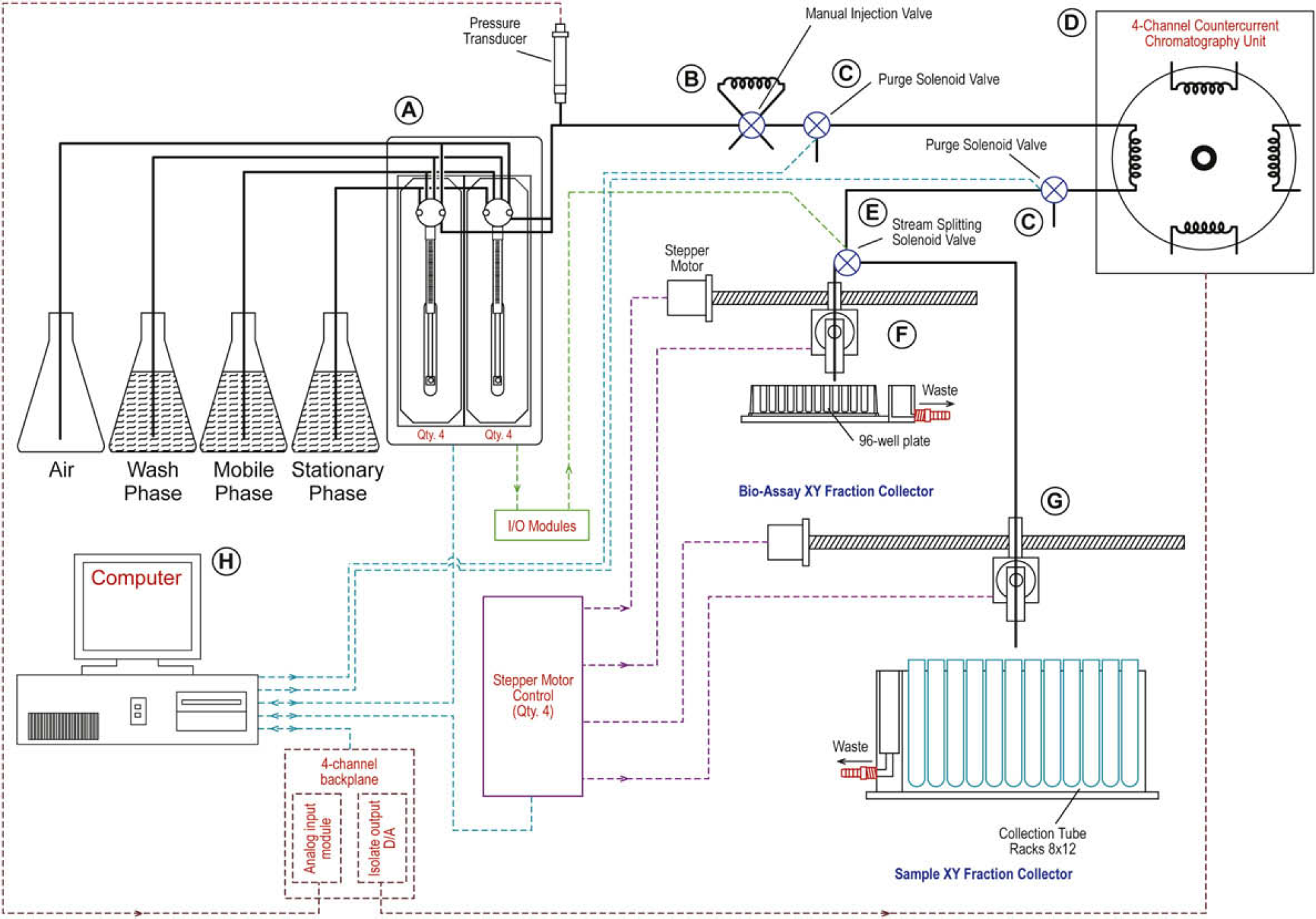
This figure displays a schematic representation of each of the major hardware components of the countercurrent chromatography (CCC). Working clockwise from the upper left of the diagram, (
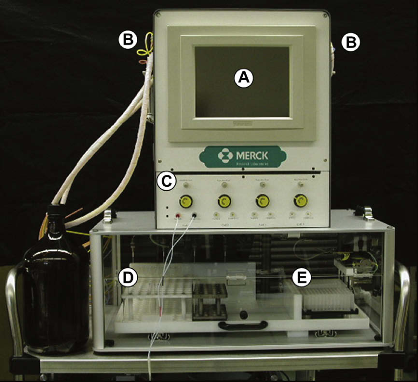
This figure is taken from the front of the countercurrent chromatography workstation built in-house for natural product separation and purification. The workstation was assembled to be mobile and was built on a movable cart. The figure shows the Advantech PPC-103 (
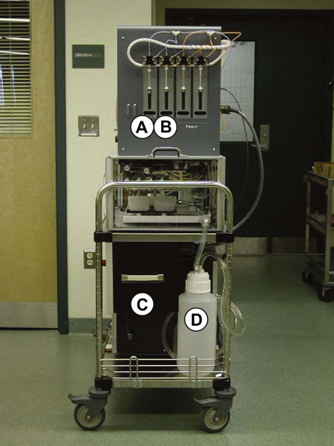
This figure was taken from the right side of the countercurrent chromatography workstation. The figure shows two (of four) Kloehn C50300 pump pairings. Pumps A and B operate in a “push/pull” fashion. Both pumps are connected to the same solvent source and while pump (
The coil planet centrifuge was equipped with two bicoils each containing two 165 mL PTFE coils. Each coil consisted of 1.68 mm I.D. PTFE tubing wrapped on central spool in a spiral manner resulting in 17 layers of tubing, 10 loops each, with a β range of 0.5–0.85. The instrument was rotated in the forward direction at 800 rpm throughout the entire separation. A biphasic solvent system of hexanes:ethyl acetate:methanol:water (3:5:3:5, v:v:v:v) was used with the lower phase being the stationary phase and the upper phase acted as the mobile phase. The mobile phase flow rate was 3 mL/min in the tail to head direction in both elution and extrusion modes.
The workstation was designed and built for the EECCC fractionation of crude natural product extracts. It contains four individual chromatography coils operated in parallel. Attached to each coil is a pair of syringe pumps, each having a 1 mm syringe barrel and each partnered to work in conjunction with the other. Operating in a push/pull fashion, the pumps push solvent through the coils during the course of a CCC run. Although one syringe aspirates, the partnered pump dispenses. After a dispense cycle for one pump completes, that pump switches roles to aspirate; conversely, the pump that was aspirating switches over to dispense mode. To insure the aspiration cycle completes before the dispense cycle of the partnered pump commences, the speed of aspiration occurs faster than the dispense speed. Operating a pair of pumps in such a fashion guarantees that there is always a full syringe barrel; therefore, continuous solvent flow.
In-line with each coil are three three-way isolation valves. Two of these valves, the precoil and postcoil, are used to control solvent flow and act as pressure relief valves. The syringe pumps cannot operate with fluid pressures that exceed 100 psi. If a pressure spike would occur, it would be identified by the pressure transducer. Subsequently, either one of the precoil or postcoil three-way isolation valves would be opened to direct solvent to the waste to relieve and relegate the pressure below the 100 psi limit.
The third three-way isolation valve is for in-line stream splitting of the eluate. Stream splitting provides the ability to simultaneously collect chromatographic fractions into two types of lab ware: 96-well microplates and 16 × 100 mm test-tube racks. The concept during stream splitting is that as the eluate passes through a three-way valve it can be directed (or split) in one of two directions: toward the test tubes or toward a 96-well plate (see Fig. 4). The frequency at which the valve position switches position dictates how representative the samples are in each of the lab ware. The frequency of the chopping and the size of the subportions are definable by the chemist through the software interface. The period of time that the valve spends in that position is calculated by first dividing the specified fraction volume by the solvent flow rate. That quotient is then divided by the frequency to give a time, in seconds, that the valve spends directing liquid to the 96-well plate.
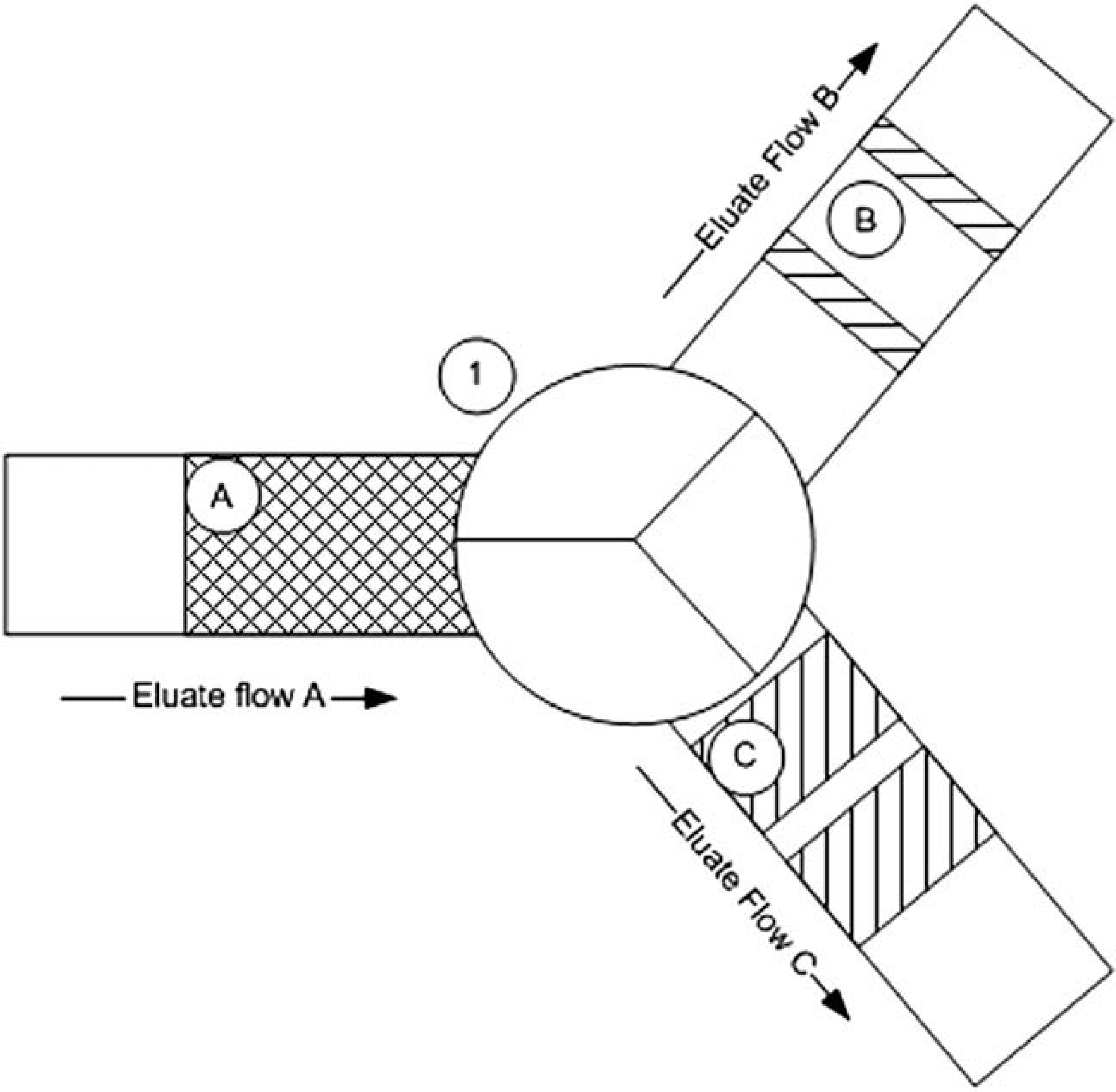
This figure depicts the concept of eluate stream splitting. As eluate from the countercurrent chromatography column flows (Eluate Flow A) into the stream-splitting valve (1) it is directed to one of two fraction collection devices: microplate or test tube. The stream-splitting valve directs a definable portion of Eluate A into the pathway for Eluate Flow B and/or Eluate Flow C. Before entering the stream-splitting valve, Eluate A is composed of Eluates B and C. Eluate flow in this diagram is from left to right.
The stream-splitting functionality eliminates the need to manually transfer aliquots of eluate from the test tubes to microplates, and if the functionality is turned off the whole fraction volume is collected into the array of test tubes. Typical fraction volumes in the 96-well plate range between 200 and 500 μL/well, while collecting in the test tubes allows for collecting 9–10 mL per test tube.
The computer controlling the workstation is an Advantech, Inc. PPC 103 touch screen with a panel mount. This computer offers space-saving benefits; the dimensions are 11 in. tall by 13 in. wide by 3 in. deep. It has four integrated COM ports, two PS2 ports, two USB 1.1 ports, one parallel port, and a touch-screen monitor with a maximum resolution of 800 × 600 pixels.
Software Architecture
One of the challenges of software engineering is to hide the complexity of the hardware from the user. The software for this project was architected on three distinct object-orientated tiers with all coding done in Visual Basic 6.0. Writing any software application requires the incorporation of different software components, and in this project, due to the custom nature of the instrumentation, each of the software components were written from scratch. The final result was a software application named C_Cubed.
The user interface sits at the highest level and exposes the appropriate functionality of the application to the user. The middle layer is a custom scheduler allowing for multitasking of instrument commands, database communication, and ancillary functionality. At the lowest level sit all of the device drivers for the sensors and hardware controllers.
The user interface is written as a Wizard-style interface that captures all of the settings for a particular separation run. It asks the chemist for specific information necessary to run the instrument. After all of the steps are completed the interface generates a text-based schedule file that the middle tier then uses to coordinate operation of the components.
The middle-scheduling tier contains all of the logic to interpret the contents of the scheduling file and to decide how best to route the commands to the various hardware components. It also checks sensors while the machine is in use to insure proper functioning.
At the lowest software level sit the device drivers for each of the hardware components. The device drivers are written as ActiveX dll's to control the Kloehn syringe pumps, IMS stepper motors, and Analog Devices control modules. They were designed to take the deliberate properties of each component and expose to the next highest tier an emergent property. For example, to use a syringe pump there are three separate software commands that must be sent to the physical pump in order for the pump to aspirate properly. The three separate commands are considered deliberate properties. However, the next highest software level does rely on these commands to instruct the syringe to aspirate. A function in the low-level ActiveX device driver called “Aspirate” combines the commands to make them emergent.
Additionally, reuse of code is a high priority for any computer programmer. The design efforts of C_Cubed were focused on allowing reuse of code for future software projects. The software was written to be flexible, as well as usable for future applications.
A Wizard-Style User Interface
One of the key goals was to make the control software as simple to use as possible. During software development, a great deal of effort went into making an easy to use and functional piece of software. A Wizard-styled interface was the best approach to make the workstation straightforward for a chemist to operate (see Fig. 5).
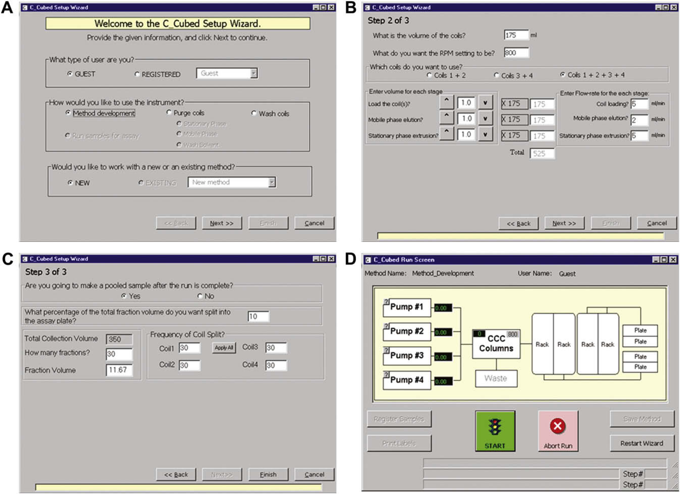
This figure shows the four screens of the Wizard interface used on the touch-screen application. In screen A, the application determines how the countercurrent chromatography (CCC) will be used. It first determines what type of user is working with the instrument, how the instrument will be used, and whether a previously saved method will be run. Once the user touches the “Next” button screen B is displayed. In screen B, all of the physical properties of the CCC coils are entered, how many coils will be used for the separation, as well as what the solvent flow rate will be for the run. After the user clicks “Next” again, screen C is shown and fraction collection information for the run is gathered. Variables such as the number of fractions to collect, the fraction volume, and how frequently the eluate stream will be split (see also Fig. 4) are examples of information the user must specify. The schedule file for the run is created when the user clicks the “Finish” button on screen C, after which Screen D is then shown. Screen D, also known as the Run Screen, gives feed back to the user while the workstation is in operation.
Each CCC method consists of four distinct stages: stationary phase filling, sample introduction, mobile phase elution, and stationary phase extrusion. All of the coils are first loaded (filled) with stationary phase solvent during the initial stage. A sample is then introduced into the separation column in the second stage. The third stage is mobile phase solvent elution, which carries the sample through the coil and provides a separation gradient. The final stage is a stationary phase solvent extrusion where the contents of the coil are forced out. Each stage can vary by solvents used, volumes, and solvent flow rate.
Other variables that were incorporated into the instrument include the number of coils to be used in a run (either two or four), the volume of liquid the coils can hold, which pairing of coils to use, number of fractions to collect, the volume of fractions, whether to perform stream splitting, and the frequency of the splitting. The workstation can also be used in four different modes: purging, washing, method development, and assay fractionation. Each mode requires a unique combination of the variables described. For instance, method development has a purging/washing step, whereas separation of real samples requires all of the variables for a method development run. C_Cubed's wizard was designed around this hierarchy and will change the number of Windows forms the user interacts with based on the way the chemist wants to use the instrument.
The user interface to C_Cubed was designed to use only the touch screen and to collect all of the information necessary to configure the workstation. A computer without a mouse or keyboard presented problems for entering numeric data that was necessary for each type of run. Likewise, entering text was a challenge. The data entry problem was solved by developing a keyboard control for the interface, similar to those that appear on any personal data assistant or handheld computer input device. The control would automatically appear when a user was challenged to enter information.
Finally, due to the length of time needed to enter all of the data required to run the instrument, the option of saving run parameters is also included. This functionality allows the chemist to save his settings at the end of a run and recall them the next time the instrument is used. To recall parameters, the first screen of the Wizard asks the user if he would like to enter the parameters of a saved run. Similarly, before exiting the application, a user is prompted to determine if he would like to save the parameters for a future use.
All answers to the questions asked by the interface are interpreted and result in a text-based schedule file containing instrument commands. This file is automatically generated by the Wizard and is subsequently used during the middle-scheduling tier of the software while the instrument is running.
Routing of Commands
To be able to maintain the integrity of the chromatography performed on the instrument, multiple tasks must be able to occur at the same time. Examples of functions that must occur concurrently include continuous solvent flow, one pump is aspirating while the partnered pump is dispensing, moving the location of the fraction collector at the same time a syringe pump is dispensing, and monitoring all of the sensors while instrument tasks are being carried out. The main challenge that had to be overcome is Visual Basic 6.0s inherent behavior to run all code on a single thread. Threads are separate simultaneous streams of execution that share resources. A single thread executes one task at a time and waits for each to finish before starting the next. 17 The ability to decide what tasks can be done concurrently and execute these tasks was paramount to the operation of the workstation.
The strategy used to make C_Cubed (and VB6) a multitasking application was twofold: to use a timer ActiveX software control and to use memory space. The schedule file is used only once during the run. It is opened, decoded, and placed into a series of tracking arrays created in memory. Once the tracking arrays are created, the file is closed and not used again during the course of a run. The software timer was integrated by writing code in VB6's timer event procedure. That code would loop through each of the arrays to determine if a command could be sent to the hardware.
A scheduling class was written to control the routing of the commands to each of the hardware components. Inside the scheduling class are five arrays that track the progress of a run. The first array holds a list of the commands to be sent to the instrument, whereas the other four arrays monitor parameters of those commands. One of the four monitoring arrays maintains the status of a command. The status can be “busy” or “not busy.” The second monitoring array keeps a record of whether a command has been completed by the instrumentation. A third monitoring array determines the ability of a command to run concurrently with another command. The last monitoring array keeps track of the specific piece of hardware to send a command to. By using all of the arrays, a single-thread language behaves in a multithreaded way and enables concurrent commands.
The Schedule Timer
The scheduling class was written to achieve multitasking functionality for VB6 in a single thread. The class is intended to be used in conjunction with a timer software control provided in the VB development environment to constantly monitor what is going on inside the scheduling class. Without this scheduling timer component, the instrument would not be able to do more than one task at a time.
One approach in using a timer is to include it as part of, or embedded into, the scheduling class. This approach was not taken because full control of the class by the user interface was desired. By removing the timer, full control over the events of the created class would remain in the portion of the software that instantiated it. The timer was placed onto the user interface and each time the timer event executed the programmer could code against the event. Additionally, no code would run inside the scheduling class until the timer on the user interface directed it to do so. Architecting the software in this fashion gives the user full control of the operation of the CCC.
Each time the timer event on the user interface is raised three tasks are carried out. The first is checking the status of all of the CCCs sensors. When a value indicates a problem the method is either paused or aborted, depending on the severity or sensor reporting the problem. The system alerts the user by via e-mail of the problem and a message box is displayed on the screen of the workstation.
The second task checks the status of commands sent to the CCC instrumentation. It determines if the instrumentation is busy performing a task. If it is busy, the appropriate tracking array is updated. After a task that was marked as busy completes its operation the task is marked as complete. Marking a task's status “complete” will not allow the step to repeat, but will allow the next task to start. These two trivial steps are critical for the proper operation of the instrument.
The last step checks the logic for arranging the processing of scheduled tasks. It analyzes the tracking arrays to determine what events or tasks can happen, decides if a task can be executed, and, if suitable, routes the appropriate task to the workstation to be performed.
Instrument Drivers
The instrument drivers of this project were written to control the Kloehn syringe pumps, IMS stepper motors, and Analog Devices control modules. All have the underlying architecture of ActiveX dll's: an instrument class wrapped around a low-level device driver.
Each device uses an ASCII command set to tell it what functions to perform. 18 –20 These instructions are encoded within the device driver and exposed through easy to understand language. The device driver is written to be object orientated—a software representation of the piece of hardware consisting of the commands necessary to carry out the desired tasks. It is an exact copy of the hardware functionality represented in software commands. It contains all of the properties (settings), methods of functions (actions), and events (status) of the corresponding piece of hardware.
Using the Kloehn syringe pump as an example, the driver contains such configuration properties as pumping speeds, communication port settings, syringe positioning, valve types, and syringe volume. The pump can perform certain encapsulated tasks such as aspirating and dispensing liquid. Keeping that in mind, the methods included in the driver for the pump are Aspirate, Dispense, and Abort. When the instrument driver receives a request for either a property or method, it interprets the command, converts the command into the proper ASCII character string, or series of strings, and sends it to the pump.
Each driver notifies the scheduler when if it receives or completes a command by raising either an OnComm or an OnCompletion event, respectively. These events give the scheduling class the ability to perform another task after one has been sent and executed. The scheduling class listens for a return event from the device driver, indicating how the command was received and/or performed by the piece of hardware. Once this event is captured by the scheduling class the information can be logged or another task can be carried out. Architecting the device driver in such a fashion allows for real-time logging and knowledge of what is being done by the hardware devices.
Experimental Use
Operation of the instrument consists of four main steps: (1) “filling” of the CCC coil with the future stationary phase of the solvent system; (2) “injection” of the sample and simultaneous starting of mobile phase flow and centrifuge rotation to establish the hydrodynamic equilibrium; (3) mobile phase coil elution; and (4) stationary phase coil extrusion.
When performing the first step, a solvent system is chosen for the separation and premixed in a separatory funnel. The upper and lower phases are separated and placed into separate reservoirs. These reservoirs then become the stationary and mobile phases during instrument operation. The chosen stationary phase is then pumped into the CCC coils at 5 mL/min until 1.3 coil volumes is pumped through the tubing. This step is performed with the centrifuge turned off.
The sample is then loaded into the sample injection loop, and the separation begins when the user hits the “Start” button on the user interface. At that moment, the coil rotation begins and the speed is gradually increased to 800 rpm, the mobile phase flow starts at 3 mL/min, and the sample is introduced into the mobile phase solvent stream by manually turning the sample valves to the inject position.
Mobile phase coil elution is typically performed at 3 mL/min (for 1 × coil volume); and 19 × 9.67-mL fractions are collected simultaneously into 16 × 100-mm borosilicate glass test tubes and an assay aliquot into a 96-well plate at a stream split of 5% and a frequency of 50 cycles.
Lastly, the stationary phase is extruded for 1.1 coil volumes using stationary phase solvent at the identical fraction collection frequency as the mobile phase. The result is another 19 fractions in both the test tubes and 96-well plate. After this step is completed, the centrifuge is turned off and the rotational rate returns to zero.
An example of the experimental use of the workstation is shown in Figure 6. Thirty-three bioactive fermentation extracts from an antifungal screening program were subjected to a standardized EECCC fractionation with this instrument.
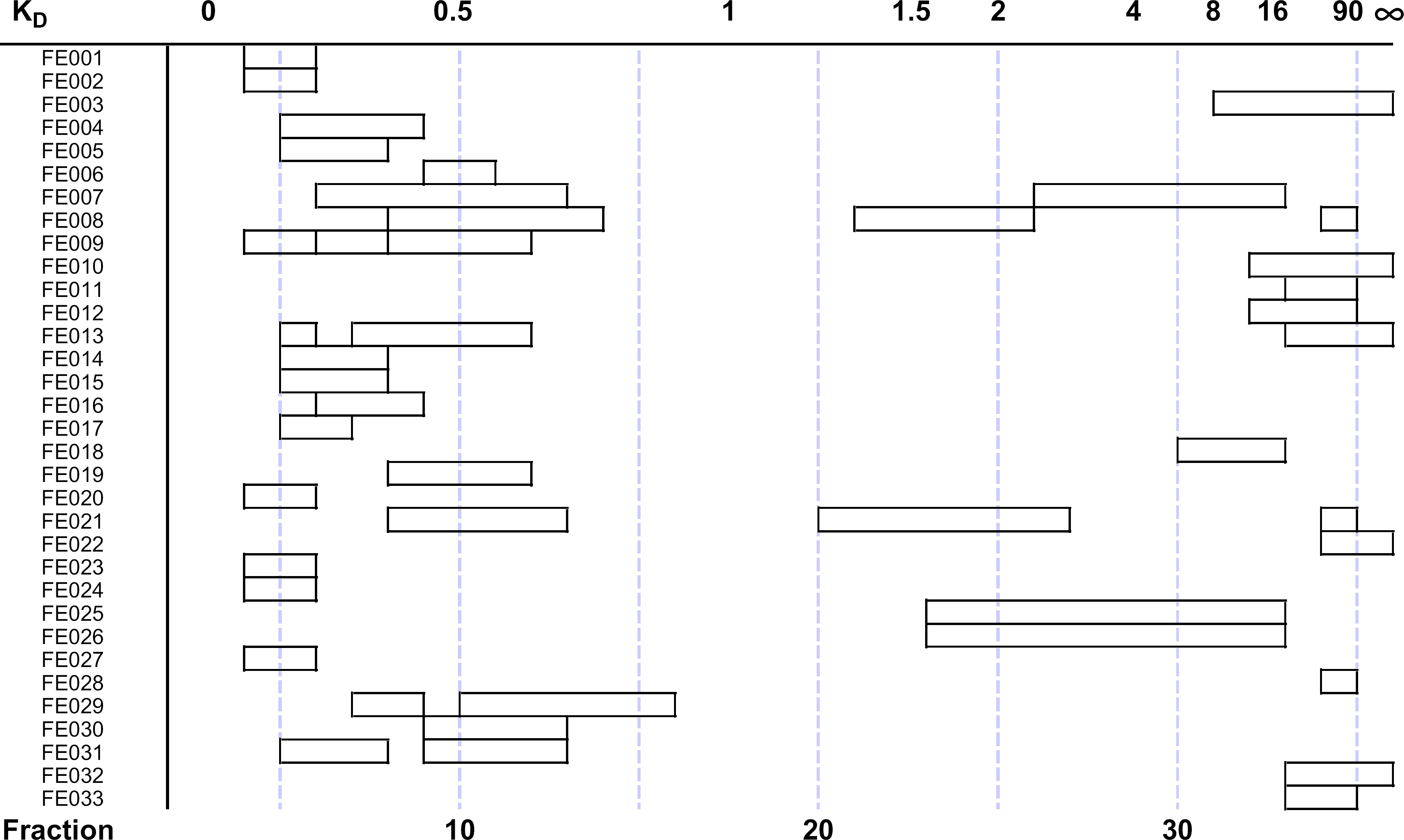
The distribution of antifungal activity in a set of 33 fermentation extracts is shown versus the fractions that the activity eluted. Using the average percentage of stationary phase contained in the coil at equilibrium (stationary phase fraction, Sf ) of 0.85, the elution positions are also shown in terms of the observed distribution coefficient (K D).
An example of the experimental use of the workstation is shown in Figure 6. Thirty-three bioactive fermentation extracts from an antifungal screening program were subjected to a standardized EECCC fraction with this instrument.
Fermentation samples were prepared by extracting 50 mL of fermentation broth with acetone. The clarified acetone extract was then subjected to solid phase extraction using a column of Mitsubishi CHP20P (bed volume 5 mL). The column eluate was concentrated to dryness and dissolved in 5 mL of the upper phase and 5 mL of the lower phase of the solvent system for injection. Fraction aliquots were prepared for bioassay by concentration to dryness in a SpeedVac concentrator and then dissolved in 25% DMSO. Antifungal activity was determined by standard agar diffusion assay using a strain of Candida albicans.
The fraction aliquots that were collected into 96-well bioassay plates and 16 × 000-mm borosilicate glass test tubes in a 1:20 ratio using the stream-splitting functionality were evaluated for antifungal activity. The open bars represent the distribution of antifungal activity for each sample versus the fractions in which it eluted. Using the exact percentage of mobile and stationary phases at equilibrium for each sample the elution of each component, or activity zone, can also be described by its distribution coefficient (KD). Immediately obvious from this set of samples is that the entire fractionation range, from KD of 0.0lel00, is used with this technique. Multiple zones of bioactivity were resolved in several of the samples, FE007, FE008, and FE21, for example. In practice, once the bioactive fractions are determined the remaning 95% of the sample contained in the test tubes can be recovered and used for further work (Note: 5% was consumed during the analysis of the 96-well bioassay plate and does not represent loss due to fraction retention on the EECCC column).
Conclusion
A computer-controlled completely integrated CCC workstation that provides the necessary features of continuous solvent pumping, separation of extracts, flexible fraction collection, and stream splitting of the eluate was created. A single workstation was produced and used for a variety of separations of crude natural product extracts.
This project also demonstrated how one could architect and build a software application to exhibit a multithreaded behavior while maintaining a single thread. The importance of this feature is that a single thread is easily controlled and monitored. Additionally, a commonly used programming language was used. Furthermore, the completion of this project also shows that there is still a niche for custom instrumentation within a pharmaceutical company. Due to the potential parallel processing of up to four natural product extracts, including this instrument as a routinely used research tool allows for the rapid chemical separation, biological screening of the fractions collected (in both test tube and a microplate), and subsequent structure elucidation that have previously taken significantly longer.