
Abstract
Despite advances in laboratory automation, many sample handling tasks remain a manual process. SHOW (Sample Handling Operation Wizard) is a computerized system developed to guide manual sample handling. It consists of an illumination station equipped with a flat panel computer monitor, a sample tray holding up to four microtiter plates and up to eight vials, and a computer installed with custom software. The sample tray, loaded with plates and vials, is placed on the illumination station, which displays images of wells and vials directly below. Plate format can be set by the user to fit 24-, 48-, 96-, or 384-well plates. By illuminating the wells or vials involved in a sample handling step of a predefined protocol, manual operations can be performed with precise guidance from the system, and sample properties or experimental data can be recorded by clicking on the corresponding well images. As a result, the risk of locating a wrong sample or placing a sample at a wrong location is minimized, and sample handling operations become more efficient and less stressful.
Introduction
Sample handling in the laboratories is carried out in either manual or automated fashion. Manual operations are performed, typically without computerized guidance, by using a handheld pipette if the sample is liquid, or by hand if the sample is in a removable container such as a vial. Robotic systems are available for automatically handling large numbers of samples according to predefined protocols. In recent years robotic systems have been widely used for liquid handling in combinatorial library synthesis, high-throughput screening, and sample management. Examples of robotic liquid-handling systems are Tecan Genesis (Tecan Group Ltd, Maennedorf, Swizerland), Tomtec Quadra96 (Tomtec, Hamden, CT), and Beckman Biomek 2000 (Beckman-Coulter, Fullerton, CA). Although these systems can perform high-throughput tasks, they are complex, expensive, large in size, and not portable.
Due to the limitations of the robotic systems, scientists and technicians routinely perform manual sample handling for lower throughput tasks without using robotic systems. To reduce errors, some follow a sketched diagram or printed instructions of a protocol. Although these methods work well for a small number of samples, when sample containers with a nontrivial number of samples, such as 24-, 48-, 96-, or 384-well microtiter plates are used, error in locating samples in a manual process is a major concern. Manual sample handling remains tedious, stressful, and error-prone. In addition, the operational details of manual sample handling are often not recorded, making subsequent error checking difficult or impossible.
A few systems assisting in manual sample handling have been developed in recent years. A pipetting assisting device, MemoWell (Matrix Technologies Corporation, Hudson, NH), provides visual indication of microplate well location. Light emission diodes (LEDs) are built in the hardware at fixed well locations in 96-well format. Sample transfer sequences may bepreassigned or entered by the user, and the sample wells to be handled in a step are illuminated by the LEDs. While the device is simple and inexpensive, the formats of plates used and ways of protocol definition are limited.
Microplate Indexer (V&P Scientific, San Diego, CA) uses a single LED to highlight the well of interest. The user positions a 384-well microplate into a nest and adjusts the vertical and horizontal sliders to the row and column of the well, placing the selected well over the LED. The process tends to be tedious and time-consuming if there are more than a handful of wells to deal with. The device is also limited to one well per step and does not support multichannel pipetting.
Another product related to guided manual sample handling is the IRORI Matrices with Memories sample sorting system (Discovery Partners International, San Diego, CA). This system relies on a radio frequency tag to track each sample in a small vessel. To sort each sample vessel into a container, a set of LEDs is placed on a set of containers with wiring connecting each LED with a scanner. When a radio frequency tag in a vessel is scanned, an LED is turned on instructing the operator to place the sample in the designated container. Although the IRORI system is flexible, it requires storing samples in small vessels, an operation that may not be feasible in many situations.
SHOW (Sample Handling Operation Wizard) is a computerized system developed to guide the transfer and movement of experimental samples. The goal is to provide the user with a flexible and robust mechanism to execute predefined experimental protocols manually with increased efficiency and accuracy.
System Design
The SHOW system consists of three basic components: an illumination station equipped with a flat panel computer monitor, a transparent sample tray for holding sample plates and vials, and a computer system loaded with a software package for controlling the operations of the system (Fig. 1). Plates are mounted on the sample tray at fixed positions. The sample tray is placed above the illumination station so that the images on the monitor controlled by the computer software match the sample containers above the images. To indicate the sample or samples to be transferred, the source and destination wells are highlighted in blinking colors. Detailed instructions, such as transfer volume, are shown simultaneously in a text box in the lower section of the display panel. The user transfers the sample by using a handheld pipette as instructed by the system. Stepping on a foot switch connected to the computer signals the completion of the current step and advances the operation to the next step. Obviously, the samples must be clear and the sample containers used must be transparent enough for the user to see the images on the display panel through the container.
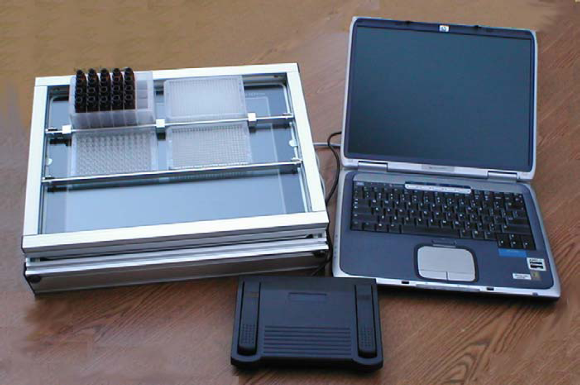
Hardware configuration of the SHOW system, including an illumination station with sample tray, a computer with software installed, and a foot switch. Up to four plates and up to eight vials may be loaded in the sample tray at a given time.
The software of the SHOW system is a stand-alone Windows application developed using Microsoft Visual Basic.Net (Microsoft Corporation, Redmond, WA). A custom Windows Control was developed as plate images with properties exposed to the client application. The properties of the plate control include number of rows, number of columns, plate width, plate length, plate color, well size, well color, and well flashing color and frequency. The plate control has a list of well objects with well index, row, column, color, size, and flash-rate attributes. Four plate controls are instantiated in the application to represent four plate images (Fig. 2). The properties of these four plate controls can be directly configured by the user. For example, the user may set any one of the four plate controls to be 24-, 48-, 96-, or 384-well format. A fifth plate control with eight rows and one column represents the vial rack.
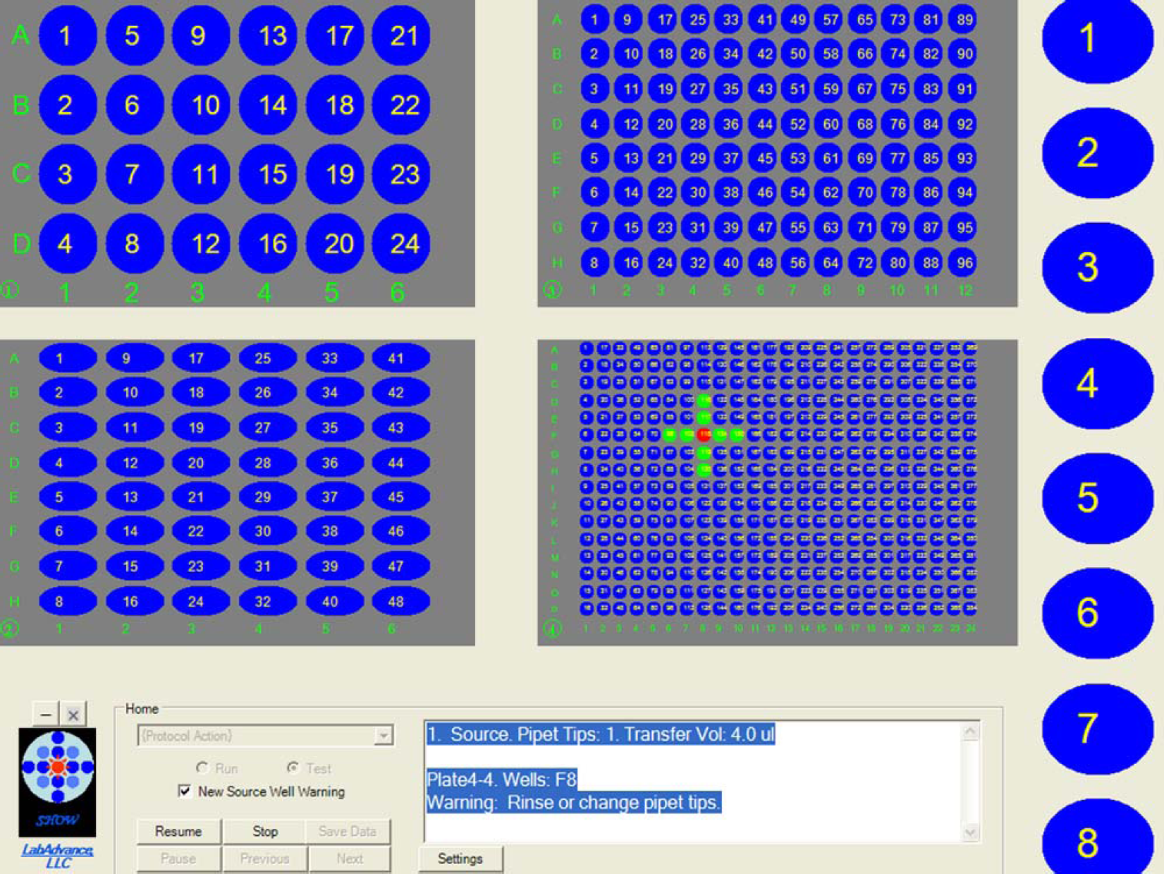
The graphical user interface of SHOW, including four plate controls with adjustable properties, a vial rack control, and a menu supporting the software functions. Well F8 of Plate 4 is highlighted in red, signaling the source well from which a sample should be taken. The wells in green that form a cross help locate the well. Details of the sample transfer, such as transfer volume, is displayed in the text box in the lower right corner of the interface.
To highlight a well, a cross pattern, as shown on the 384-well plate control of Figure 2, can be displayed for easy well identification. This cross pattern is particularly helpful for higher density plates, such as 384-well plates, or plates with high-curvature well bottoms.
In addition to plate and vial rack images, the graphical user interface of the application also includes a menu to provide functions for opening, editing, saving, importing, and creating a protocol. After a protocol is loaded, it may be tested or executed, as shown in the flowchart (Fig. 3).
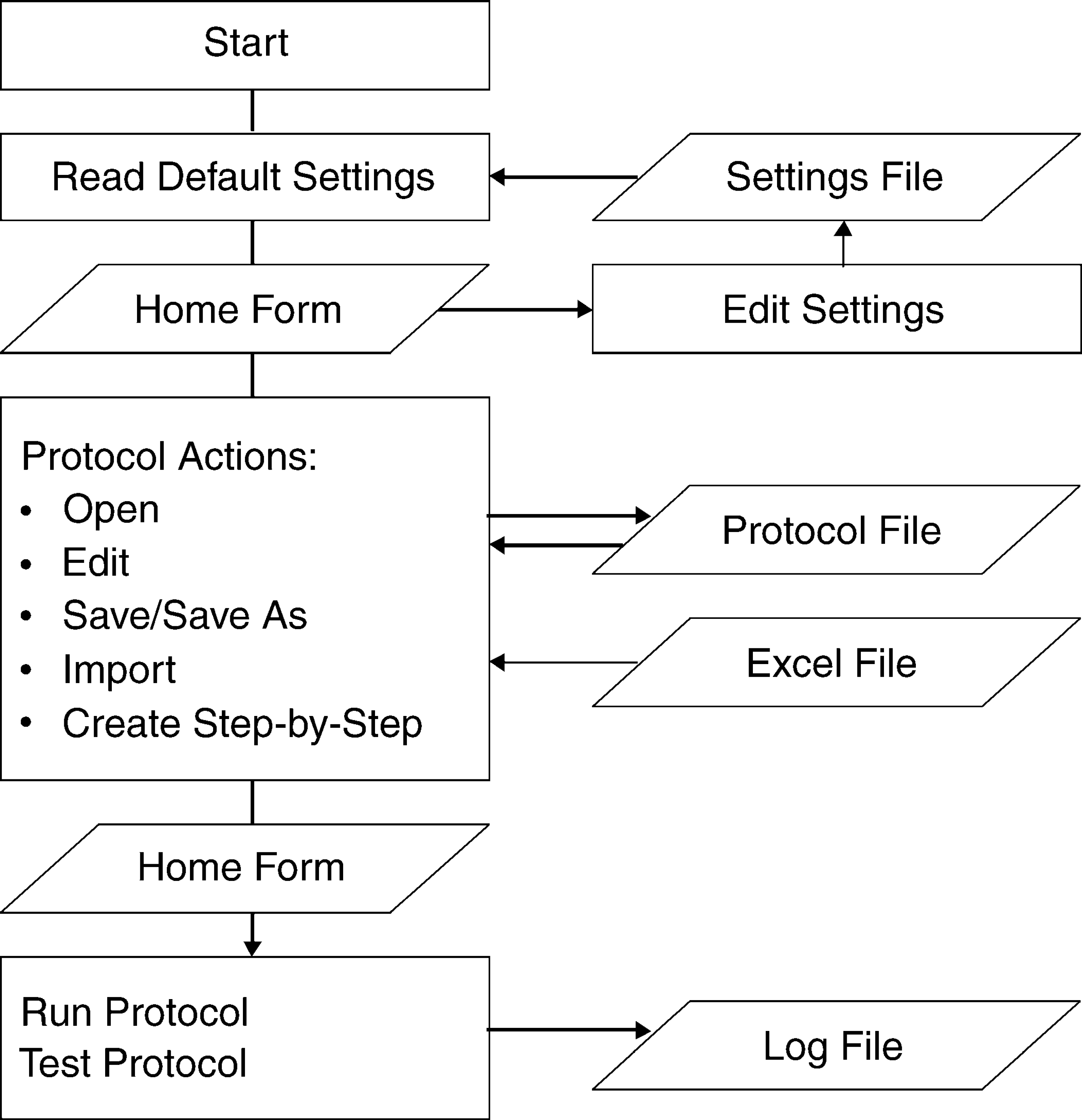
The workflow of the SHOW system. Upon starting the program, default settings are read from a settings file. Settings may be edited and saved. The user may perform the following protocol operations: open, edit, save, save as, import, and create step-by-step. Protocols are saved in a protocol file. The import function reads well mapping information from an Excel file. Once a protocol is loaded, it may be tested or executed. The execution time for each step is recorded in a log file.
At the start of the program, default settings such as plate format, well color and size, and highlight color and flash rate are read from a settings file in XML format. 1 Users may adjust these configuration parameters and save them back to the settings file. A segment of the setting file is shown in Figure 4.
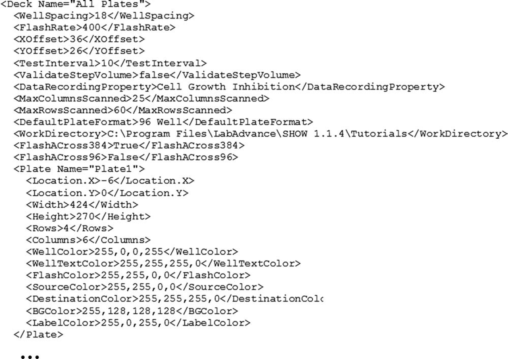
A segment of the settings file in XML format.
A SHOW protocol is a set of sample transfer steps. A protocol may include one or more plates. It may use vials or external containers. External containers are large containers, such as solvent bottles, that do not fit on the sample tray. If more than four plates are used, the steps are grouped into tasks, with each task having four or less plates that can be mounted on the sample tray simultaneously. While executing a protocol, the user is instructed to change plates between tasks.
The user may open an existing protocol, or create a new protocol by either importing from an Excel file (Microsoft Corporation, Redmond, WA) through the Import function, or defining the protocol step-by-step within the application through the Create Step-by-Step function. When importing from Excel, the minimal information required in the Excel file is source well location. Other information such as destination wells, plate format, and transfer volume can also be specified. If no destination wells are specified, the samples are mapped systematically by row or by column. The system tracks the number of plates imported and breaks them down to tasks, with each task performing operations on a set of four or less plates. Multiple wells may be specified for a step, signaling the usage of a multichannel pipette. External containers may be included. At run time, use of external containers is indicated in the text instructions shown on the display panel.
The Test function runs through the steps of the protocol continuously without waiting for the user to signal the completion of the physical operations. The user may also use this function to review and validate a protocol, or to demonstrate a protocol to others for educational or training purposes.
The Execute Protocol function is used to guide physical operations as defined in the protocol. During execution, sample container images are generated on the display panel as signals to guide the user to execute individual operations, such as taking a sample from a source well and dispensing it into a destination well. For example, flashing a well in red indicates the location to take a sample; flashing another well in green indicates the location to dispense the sample. Details of the sample handling step and related information, such as amount to transfer, are displayed in a text box. Upon the completion of sample handling for the current step, the user signals to the system by stepping on a footswitch. The relevant information of this completed step, such as time of execution and notes from the user, is saved in a log file.
Applications
The SHOW system is a general purpose guiding device. It may be used for any laboratory tasks where liquid or vials need to be moved between plate wells and other containers. Below is a list of selected applications of the SHOW system.
Parallel Chemical Synthesis
The SHOW system helps execute parallel synthesis tasks, such as reagent dissolution and addition to the synthetic vessels. After the completion of synthesis, it guides the transfer of products to analytical plates for QC and to storage plates for further distribution. Focused libraries and diversity-oriented synthesis for lead optimization typically include tens or a few hundred compounds. The SHOW system is well suited for manual parallel synthesis of such compound collections. Creating a typical parallel synthesis protocol for the SHOW system involves the following stages.
For multistep reactions, the reagent weighing, dissolution, and addition steps are repeated according to the plan.
A sample Excel template file for parallel synthesis is shown in Figure 5. In this template, four reagent A and four reagent B are used to produce a 4 × 4 library. The reagents are weighed and dissolved in 8 vials. The reagent solutions are then transferred to the synthetic plate, with reagent A-1 to A-4 distributed by column and reagent B-1 to B-4 distributed by row.
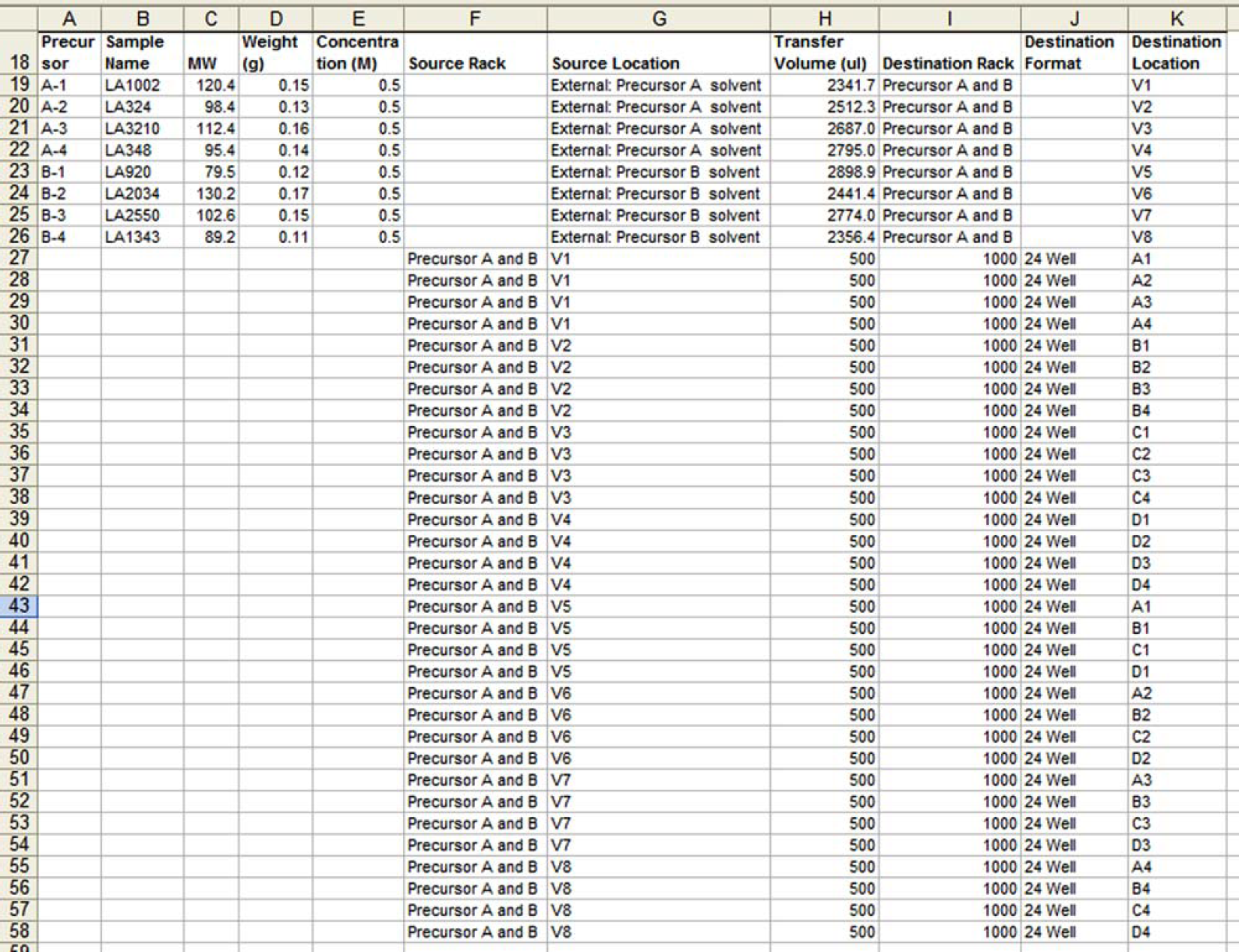
A sample Excel template file for a 4 × 4 chemical library.
When the reagents are weighed, the actual weights are recorded in the Weight (g) column. The text “External: Precursor A solvent” in the Source Location column indicates transferring solvent from an external container. The transfer volume is calculated from the weight and the predetermined concentration of the reagent. The text “V1” in the Destination Location column indicates that the solvent is dispensed to the first vial in the vial rack. The subsequent rows of the template dissolve the remaining reagents and transfer the reagent solutions to the plate wells.
Biological Assays
Biological assays require addition of buffers, reagents, dilution solvent, sample solutions, and control solutions to the wells of a plate. The SHOW system can be used to guide such liquid additions. Serial dilution is a simple and common procedure in biological assays, but a single pipetting positioning error can ruin the whole assay. The SHOW system can provide precise pipetting positioning indication for serial dilution, which is particularly valuable for assays using 384-well plates.
In some biological assay experiments, the results can be determined visually with the assistance of the SHOW system. For example, in minimal bacterial inhibition concentration (MIC) assays, the assay plate is prepared by serial dilution of a chemical compound that inhibits bacterial growth. Bacteria are then added to the wells of the plate. Bacteria may grow in wells with lower concentrations of the compound, but may not grow in wells with higher concentration of the compound. After visually inspecting the growth of bacteria in the serially diluted samples, one may easily record the sample with the lowest compound concentration that inhibits bacteria growth by simply clicking on the corresponding well. The MIC value is then automatically recorded.
Sample Management
There are many tasks in sample management, such as compound plating, picking compounds based on certain properties (cherry-picking), and vial sorting. All of these tasks can be assisted by the SHOW system.
Typically, the samples to be picked are specified in an Excel file. The file can be imported and the source wells are systematically mapped to the destination plates. When the protocol is executed, the source and destination wells are highlighted. Up to three source plates and one destination plate may be mounted on the sample tray. When all three source plates are picked, or when the destination plate is full, the system instructs the user to load new plates.
Conclusions
SHOW, a computer guiding system for manual sample handling, is described. The system is simple, robust, and portable. It enhances laboratory productivity and minimizes errors. This system can be used in liquid transfer with handheld pipettes, or manual vial sorting. The SHOW system is an attempt to address the unmet sample handling needs of pharmaceutical, environmental, and other scientific research. It can be applied to diversity-oriented synthesis, biological assays, sample management, and data recording.
Acknowledgment
The author would like to thank Dr. Hanghui Liu for the support and guidance in conceiving, designing, and implementing the SHOW system.