
Abstract
The automation of biological laboratory assays may require lengthy incubations of reagents on the work surface of a pipetting robot. Commercial devices are readily available for keeping these reagents accessible and warm, but there are few existing technologies for storing accessible reagents below the freezing point of water. Here, we introduce a low cost, small footprint, robot accessible reagent cooler, based on compressor technology capable of acting as an enzyme freezer or extreme cold reagent storage device.
Introduction
The cells, proteins, enzymes, buffers, and other substances used in everyday biological research often must be stored in a cold environment prior to use. For instance, a majority of enzymes are stored in a 50% glycerol solution at −20 °C prior to dilution and use in experiments. The commercial availability of a device that can store reagents chilled below freezing on the confined surface of a pipetting robot is practically nonexistent. The few available products are expensive and often will only fit on “enterprise-style” robotic work surfaces with larger reconfigurable work decks.
Here, we illustrate the construction of a low cost, small footprint, chilling device. We have investigated and constructed coolers based upon two refrigeration technologies: mechanical compressor/evaporator 1 and solid-state thermoelectric (Peltier effect) heat pump. 2 We also investigated two types of interfaces with the compressor refrigeration. The first uses a circulating liquid bath to remove heat from coolant, which is then pumped into a heat exchange block on the robot to cool samples. The second interface contacts the evaporator component of the compressor system directly to the heat exchange block without the use of any liquid coolant. Described in detail in this paper is this “direct evaporator contact” design (see Figure 1), the most appropriate for our application. In this embodiment, the cooler secures a standard 96-well microplate filled with various enzyme solution stocks and maintains them continuously at storage temperatures between −20 to −80 °C. Such facilitation permits uninterrupted 24-hour nucleic acid in vitro selection experiments. 3

Pictures of the direct evaporator contact low temperature microplate station. A) Arrow indicates station on a Biomek 2000 work surface. B) Close-up of rear face; Delron insulation block (1), evaporator insertion point (2), temperature probe insertion point (3). C) Immersion cooler refrigeration unit (1) with insulated hose (2) ending with the evaporator (3) that inserts into the low temperature station (4).
Materials and Methods
The Low Temperature Microplate Station is comprised of four major components; a microplate interface block that secures and cools the microplate and its samples, a heat exchange block that transfers heat from the interface block to the refrigeration unit, the thermal insulation shell, and the refrigeration unit. Presented here is the construction of a cooler employing direct evaporator contact refrigeration (Figure 2), but thermoelectric and fluid circulation technology can also be employed (see Discussion).

Schematic of direct evaporator contact design. Gray color indicates the microplate interface block, blue color shows the heat exchange block, and white represents the insulation block. Exact dimensions of the design will vary with the immersion cooler model and robot system used. Measurements are provided in millimeters.
Microplate Interface Block
The microplate interface block is easily constructed by modifying a Stratagene (La Jolla, CA) 96-well aluminum working rack. The bottom surface of the aluminum rack is planed off and polished to a depth stopping just below the pre-manufactured wells (final thickness of 12.5 mm). This modification provides an extremely flat surface for the heat exchange block to interface with and reduces the mass load that the refrigeration system must cool. A small hole (3 mm diameter) is drilled straight into the microplate interface block for the insertion of a 100 ω resistance temperature probe (FTS/Kinetics, Stone Ridge, NY) that allows temperature feedback to the digital controller of the external refrigeration system.
Heat Exchange Block
The heat exchange block is constructed of standard aluminum plate stock that is machined to the same width and depth as the microplate interface block (114 mm x 75 mm). The height of the heat exchange block is determined by the minimal height needed to accommodate the evaporator cold finger from the refrigeration unit. For the immersion cooler we used (described below), the diameter of the cold finger required the block to be machined 29 mm high. In order to maximize contact with the heat exchange block and evaporator cold finger, a 13-mm diagonal hole is drilled into this block. After construction of the sample holding and heat exchange block is completed, they are cemented together with a Thermal Interface Pad (Melcor, Trenton, NJ)—a double sided, thermally conductive adhesive pad (0.036 W/cm-°K).
Insulation
The insulation shell is constructed from either Delron (Regal Plastics, Austin, TX) plastic polymer or Styrofoam (Dow Chemical Company, Midland, MI). Delron is easy to machine to high tolerances and is extremely resistant to chemical and physical damage. Styrofoam has better insulative properties than Delron, 4 although it is easily damaged. Either insulation is machined to the largest size permissible on the robotic work surface. In this case, we machined the block for integration onto a single space on the deck of a Biomek 2000 robot (Beckman Coulter, Fullerton, CA) having external dimensions of 138 mm x 64 mm x 102 mm (Figure 1A). A square recess is then cut into the top face of the insulation block deep enough to accommodate the interface and heat exchange blocks (here, 44 mm). Holes are drilled through the back face to allow access for the cold finger and temperature probe (seen in Figure 1B). Additional holes can be drilled on the bottom of the insulation block for insertion of alignment pins that interface with the robotic work surface. In order to prevent condensation from forming on samples while the station is in use, the microplate is sealed with Aluminum Sealing Tape (Nalge Nunc Int., Rochester, NY) that is easily penetrated for robot pipette access.
Refrigeration Unit
There are a number of commercially available refrigeration units designed to allow direct contact to the evaporator. They are generally marketed as “immersion coolers” for use as an alternative to dry ice in vapor traps. For our design, we used the FTS/Kinetics (Stone Ridge, NY) FC55A01 model with the flexible cold finger option capable of cooling to −80 °C. Other models offered by FTS and other companies are capable of cooling to at least −100 °C. The Low Temperature Microplate Station design described here specifically interfaces with the FC55A01 cold finger and temperature probe.
Once the microplate and heat exchange blocks are assembled and placed within the insulation shell, the cold finger of the refrigeration unit and temperature probe are inserted into the appropriate drilled cavities. Liberal amounts of Z9 Silicone Heat Sink Compound (GC/Waldom, Inc., Rockford, IL; 0.008 W/cm-°K) are applied to both cavities in order to maximize the thermal transfer interface. Once the blocks, cold finger, and probe are assembled, they are glued and sealed into place with Polyseamseal All-Purpose Adhesive Caulk (OSI Sealants Inc., Mentor, OH).
Discussion
Temperature control of reagents is often a crucial step in biochemical experimentation. In the growing field of laboratory automation, the need for temperature control has additional constraints involving space and access. We describe in this paper a design capable of overcoming the challenges of achieving a large drop in temperature in a very space-limited environment, while maintaining sample access within a reasonable budget. During five years of design improvements, we have employed three major heat pumping strategies—thermoelectric heat pumps, liquid-circulating baths, and direct evaporator contact (see Figure 3). We describe in detail in Material and Methods our most optimal design, the direct evaporator contact station. Here, we contrast that design to our other attempts and explain why we consider the direct evaporator contact design the most appropriate for our needs.

Heat transfer cartoons of the thermoelectric (A), circulating bath (B), and direct evaporator contact (C) designs.
In all of our design embodiments, we have chosen to work with aluminum rather than copper for our heat exchange units. A copper heat exchange block cools reagents most quickly (Figure 4). While copper does have a much higher thermal conductivity than aluminum (4.0 and 2.4 W/cm-°K, respectively), 5 copper is much harder to machine and process than aluminum. For example, machining copper typically requires a four-fluted end mill and kerosene as a lubricant, while aluminum requires a cheaper two-fluted end mill and ethanol (requiring much less cleanup) as a lubricant. 6 Also, the only other metals with very high thermal conductivity values (gold, 3.2 W/cm-°K; silver, 4.3 W/cm-°K) 5 are extremely cost prohibitive.

Cooling speeds of different low temperature station designs.
Our lab's initial efforts at constructing a low temperature station centered on thermoelectric heat pump technology (Figure 3A). While the small size of thermoelectrics is attractive, we found the electronics expertise required to effectively use them to be a major deterrent. We were unable to produce a thermoelectric based station that could reach temperatures below −10 °C (Figure 4). The main drawback is the inability to pump an adequate amount of heat from the device. This design limitation is a result of the small footprint required of the low temperature microplate station. While it might be possible to supplement thermal exchange with external fans or ducts connected to the work surface, this increases problems relating to airborne contamination.
Our next generation strategy employed a cooling liquid circulating bath (Figure 3B). Commercially available liquid circulating baths are capable of cooling liquids to −40 °Cor more. With this high-level heat pumping capacity, we found achieving a −20 °C temperature range to be easily obtained. This design did meet all of our instrument goals but required the pumping of liquids to transfer heat from the samples to the evaporator. Pumping liquid around sensitive robotic electronics is undesirable, as there is a constant chance that the system could develop a leak during an unattended robotic experiment. Secondly, in order to effectively exchange heat between the liquid and heat exchange block, a complex serpentine fluid path must be machined into the heat exchange block. This fluid path, including the hoses and connections necessary for this design, leads to a bulkier device that becomes difficult to fit into the small footprint required for robotic interfaces. Also, the large quantity of liquid that is required to be cooled upon start-up leads to a greatly increased cooling time (Figure 4). Finally, because the liquid circulating bath is cooling to temperatures below 0 °C, liquids other than water must be employed, and we have found working with these to be unpleasant (either difficult to clean and/or toxic).
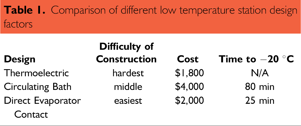
The direct evaporator contact design described in detail in the Materials and Methods section (Figure 1, 2, and 3C) has proven to be the most practical design over years of use in our lab. The simple interface of the evaporator to the heat exchange block is easy to machine and requires the least amount of robot surface space. The small mass of this station promotes most rapid cooling (Figure 4). This design does not require complicated air flow or liquid plumbing to adequately interface with the refrigeration unit. There is no chance for liquids to leak onto the robot and only one hose must be connected to the station. The simple design keeps the cost of the station low (Table 1).
Comparison of different low temperature station design factors
Acknowledgments
We would like to thank Dr. John H. Lacy (UT Astronomy Department) for his valuable design input. For assistance with construction, we thank Jack Clifford (UT Physics Student Machine Shop), Travis S. Bayer, Aaron A. Chevalier, and Dr. David Cohen. This work was supported by DARPA, Duke University, and the NIH.