
Abstract
Applications of microfluidics and MEMS (micro-electromechanical systems) technology are emerging in many areas of biological and life sciences. Non-contact microdispensing systems for accurate, high-throughput deposition of bioactive fluids can be an enabling technology for these applications. In addition to bioactive fluid dispensing, ink-jet based microdispensing allows integration of features (electronic, photonic, sensing, structural, etc.) that are not possible, or very difficult, with traditional photolithographic-based MEMS fabrication methods.
Our single fluid and multifluid (MatrixJet™) piezoelectric microdispensers have been used for spot synthesis of peptides, production of microspheres to deliver drugs/biological materials, microprinting of biodegradable polymers for cell proliferation in tissue engineering applications, and spot deposition for DNA, diagnostic immunoassay, antibody and protein arrays. We have created optical elements, sensors, and electrical interconnects by microdeposition of polymers and metal alloys. We have also demonstrated the integration of a reversed phase microcolumn within a piezoelectric dispenser for use in the fractionation of peptides for mass spectrometer analysis.
Introduction
The ability to manufacture smaller components and systems at high volumes, using photolithographic methods, has been at the heart of the growth in the semiconductor and electronics industries. The MEMS industry has begun to extend this success into devices that require more than electrical function. Accelerometers and pressure sensors are notable success areas. Ink-jet printers are a MEMS success area that actually predates the acronym.
Biologically active MEMS systems (BioMEMS) create significant fabrication challenges that are not easily addressed by conventional photolithographic processes. BioMEMS systems in general have more diversity of materials and function than conventional MEMS devices. Some materials (e.g., most bioactive materials) cannot tolerate exposure to the etching processes. The thickness added or subtracted is a limiting consideration for some materials (solders, optical materials). Molecular detection involves materials and process diversity that is analogous to having a CCD (charge-coupled device) detector with each pixel made using a different process.
Background and Applications
Ink-jet printing technology is familiar to most people in the form of desktop office printers. Actually, there is a broad range of diverse technologies that fall into the ink-jet printing category. The physics and the methods employed within this group may differ substantially, but the end effect is repeatable generation of small drops of fluid. Most of these methods fall into two general categories: Continuous mode and demand mode.
CONTINUOUS MODE INK-JET TECHNOLOGIES
In a continuous mode ink-jet printer, pressurized fluid is forced through an orifice, typically 50–80μm in diameter, to form a liquid jet. Surface tension acts to amplify even minute variations in the jet diameter, causing the jet to break up into drops. This behavior is normally referred to as “Rayleigh breakup”, based on Lord Rayleigh's observations and analysis of jet breakup in the late 1800's. 1 2 If a single-frequency disturbance in the correct frequency range is applied to the jet, this disturbance will be amplified and drops of extremely repeatable size and velocity will be generated at the applied disturbance frequency. The disturbance is usually generated by an electromechanical device (e.g., a piezoelectric transducer or speaker) that creates pressure oscillations in the fluid.
To control the uniform drops generated by Rayleigh breakup, electrostatic forces are employed. The charged drops are directed to their desired location by a fixed electrostatic field (the deflection field) to either a catcher or one of several locations on the substrate. Continuous mode ink-jet printing systems produce drops that are approximately twice the orifice diameter of the drop generator. Drop generation rates for commercially available continuous mode ink-jet systems are usually in the 80–100kHz range, but systems with operating frequencies up to 1MHz are in use. The typical drop size is approximately 150μm, but drop sizes can range from 20μm to as large as 1mm (∼0.5μL). 3
DEMAND MODE INK-JET TECHNOLOGIES
In a drop-on-demand ink-jet printer, the fluid is maintained at ambient pressure and a transducer is used to create a drop only when needed. The transducer creates a volumetric change in the fluid, which creates pressure waves. The pressure waves travel to the orifice and are converted to fluid velocity, resulting in a drop being ejected from the orifice. 4 5 6 Figure 1 shows an image of a drop-on-demand type ink-jet device generating 60μm diameter drops of butyl carbitol (an organic solvent) from a device with a 55μm orifice at 4,000 drops per second.
Drop-on-demand type ink-jet device generating 60μm diameter drops at 4 kHz. Sequence from left to right spans 130μs.
The transducer in demand mode ink-jet systems can be either a structure that incorporates piezoelectric materials or a thin film resistor. In the latter, a current is passed through this resistor, causing the temperature to rise rapidly. The ink in contact with it is vaporized, forming a vapor bubble over the resistor. 7 This vapor bubble creates a volume displacement in the fluid in a similar manner as the electromechanical action of a piezoelectric transducer.
Demand mode ink-jet printing systems produce drops that are approximately equal in diameter to the orifice diameter of the drop generator. 8 Demand mode systems are conceptually far less complex than continuous mode systems. However, demand mode drop generation requires the transducer to deliver three or more orders of greater energy magnitude to produce a drop, compared to continuous mode, which relies on a natural instability to amplify an initial disturbance. Drop generation rates for commercially available demand mode ink-jet systems are usually in the 4–12kHz range. Drops less than 20μm are used in photographic quality printers, and drop diameters up to 120μm have been demonstrated.
In general, piezoelectric demand mode technology can be more readily adapted to fluid microdispensing applications. Demand mode (both piezoelectric and thermal) can produce smaller drops with lower velocities than continuous mode. Additionally, demand mode does not result in waste or require recirculation of the working fluid. Piezoelectric demand mode does not create thermal stress on the fluid, which decreases the life of both the printhead and fluid. Also, it does not depend on the thermal properties of the fluid to impart acoustic energy to the working fluid.
DEMAND MODE DISPENSING DEVICE CONFIGURATIONS
Many drop-on-demand device configurations have been demonstrated over the past two decades. One of the earliest configurations developed is also one that is adaptable to the use of a wide range of material. In this configuration, an annular piezoelectric transducer is attached to a glass tube with an integrated orifice, as displayed in Figure 2. Since glass is the only wetted material, this configuration can be used to dispense almost any material with acceptable fluid properties (<20cp Newtonian viscosity). Devices have also been designed for high temperature operation, mainly through the selection of piezoelectric and adhesive materials, and can operate continuously at up to 240°C. Such devices have operated for several hours at 320°C and briefly at 370°C.
Single channel drop-on-demand dispensing devices, T < 100°C.
Multiple devices of the type described above may be mounted into a mechanical and hydraulic assembly to form an array to increase throughput or to dispense multiple fluids. However, many of the handling and alignment issues associated with such an inkjet array are simpler to address in an integrated array printhead. MicroFab has developed a family of integrated array printheads that are fabricated by sawing channels into a piezoelectric block structure. 9 The original 120 jet/single fluid configuration has been modified into 10 channel/10 fluid, 12 channel/12 fluid, and 16 channel/single fluid configurations for specific applications such as DNA arrays 10 and proteomics instrumentation. 11 The spacing between individual channels of the 10 channel/10 fluid configured printhead shown in Figure 3 is 2.0mm.
DEMAND MODE PRINTING SYSTEM CONFIGURATIONS
All desktop ink-jet printers have a similar configuration: the printhead is translated on one axis (nominally 100mm/s), and the paper is indexed ninety degrees to the printhead motion. For manufacturing applications of ink-jet printing technology, the substrate to be printed upon determines the machine configuration. In most cases, the substrate will be a silicon wafer, circuit board, circuit board panel, or other flat, rigid substrate. In addition, manufacturing equipment using ink-jet dispensing will have setup, alignment, and control functions not generally found in desktop printers. A stationary mounted printing device does not require a design to account for acceleration effects on the contained fluid, or the motion of service lines if a remote reservoir is utilized in this configuration. Figure 4 shows MicroFab's jetlab™ research printing platform for ink-jet dispensing application development.
Printing platform for development of ink-jet dispensing applications.
PROTEIN AND DNA DEPOSITION
PROTEIN DEPOSITION
Ink-jet printing of proteins was demonstrated in the 1980's with the printing of patterns of antibodies onto membranes, typically nitrocellulose that binds the antibody for use in diagnostic assays. 12 The diagnostic pattern consisted of a human readable display for the assay, such as a blood-typing test, in which the characters A, B, and + were used to indicate the blood type. Another example is given in Figure 5, which shows Abbott's TestPack™ product line. Here two antibodies (typically, βHCg and a control) are printed onto nitrocellulose using a two fluid continuous ink-jet printing system. In another application, piezoelectric demand mode ink-jet technology was used to fabricate enzyme membranes for ISFET biosensors, which can be considered early BioMEMS devices. 13

Two-antibody diagnostic assay (TestPack™) printed using ink-jet technology.
In the early 1990's Boehringer Mannheim (now Boehringer Roche) Diagnostics developed their MicroSpot™ system with the goal of increasing the number of diagnostic tests that could be conducted in parallel, and of increasing the sensitivity of the assay by minimizing the amount of analyte bound to the anti-body. 14 Up to 196 distinct reactions sites (i.e., spots) would fit into their disposable reaction well to be imaged using a fluorescence confocal scanning microscope. The initial pilot line used ten separate ink-jet deposition stations to deposit a total of ten fluids. Each fluid was printed into multiple spots to provide redundancy, and a real-time inspection system imaged the printed dots using a secondary fluorophore.
DNA DEPOSITION
Although the most prevalent DNA array fabrication techniques have been Affymetrix's light-activated DNA fabrication method 15 and pin transfer, ink-jet printing methods have been used by a number of organizations, both for synthesis and for deposition of oligonucleotides in a microarray format. The deposition of oligonucleotides which are synthesized and verified off-line has been accomplished by methods including the use of commercially available six color thermal ink-jet printheads, 16 and conventional fluid robots modified to hold up to 96 individual glass capillary piezoelectric demand mode jetting devices. 17 18 The chief difficulty in deposition of oligonucleotides is the number of different fluids to be dispensed, for as few as 10 to more than 100 oligonucleotides can be required for specific genetic resequencing applications (i.e., looking for known sequences or mutations).
Resequencing applications include clinical diagnostics, SNP (single nucleotide polymorphism) detection, and point mutation detection. Resequencing assays fabricated using ink-jet deposition of oligonucleotides have been demonstrated for drug resistant Mycobacterium tuberculosis, as shown in Figure 6.
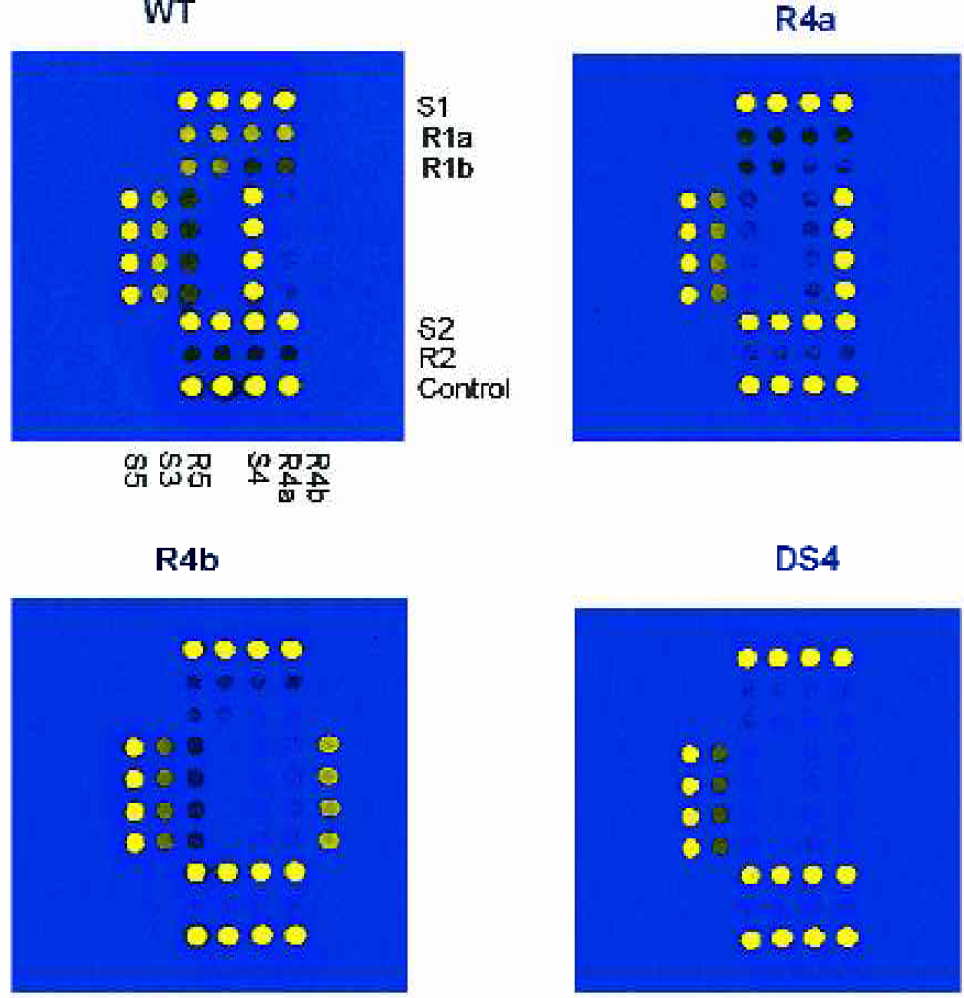
DNA test, drug resistant Mycobacterium tuberculosis ink-jet deposited spots ∼100μm (courtesy Boehringer-Roche).
CHEMICAL SYNTHESIS
DNA SYNTHESIS
Synthesis of DNA arrays using ink-jet technology greatly decreases the number of different fluids required. Only the precursor solutions of the four constituent bases (A, G, C, T) of DNA, plus an activator (tetrazole), are deposited. Each layer of bases is synthesized with only a single activation step. This is a considerable simplification compared to light-activated synthesis of DNA arrays, which usually requires four activation steps per layer. The complexity of multi-step chemical synthesis in an anhydrous environment is an added problem, but a number of investigators have overcome this difficulty. 19 20 DNA arrays manufactured in this way using ink-jet technology are available from Agilent, Rosetta Informatics, and Oxford Gene Technologies.
PEPTIDE SYNTHESIS
Peptide arrays for drug and expression screening studies 21 can be synthesized using ink-jet in a manner similar to DNA arrays, except that there are 20 naturally occurring amino acids, making the dispensing system more complex. Initial proof-of-principle peptides are currently being fabricated at MicroFab using an adapted jetlab™ printing system.
BIOPOLYMER AND SOLID SUPPORT APPLICATIONS
TISSUE ENGINEERING
The ability to “write” biopolymers, cells, and growth factors (stimulants and inhibitors) with nanoliter (and smaller) volume precision opens the possibility of digitally constructing engineered tissue using ink-jet printing technology. Bioresorbable polymers (PLGA) can be printed as a three dimensional structure, using methods of free-form fabrication, to form scaffolds in the desired tissue shape. 22 Cells seeded into this scaffold will grow into a desired shape and gradually biodegrade the polymer structure after it has been implanted, leaving only the tissue without “foreign” materials for the body to reject.
One of the primary barriers to tissue engineering is the creation of a vascular structure in tissue being engineered. By selectively dispensing biopolymers, cells, and growth factors, it may be possible to create vascular structures (and nerve conduits) using ink-jet dispensing. Figure 7 illustrates the fabrication of a polymer structure using MicroFab's ink-jet technology to create small features from bioresorbable polymers. Figure 8 displays human liver cells being dispensed using an ink-jet device. Viability testing of the cells after they had been dispensed indicated no immediate effect as the result of the dispensing process.
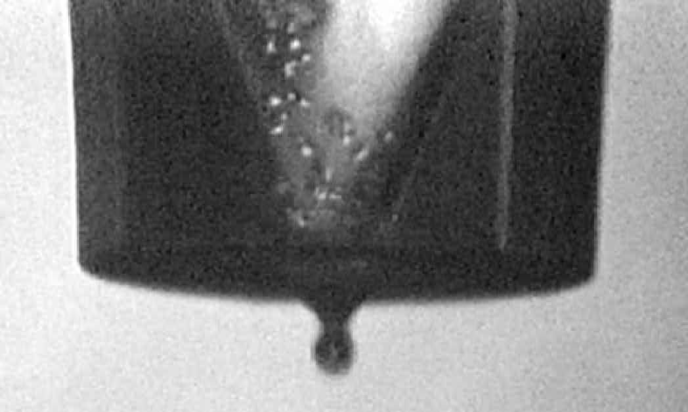
Human liver cells being dispensed using an ink-jet device.
DRUG DELIVERY
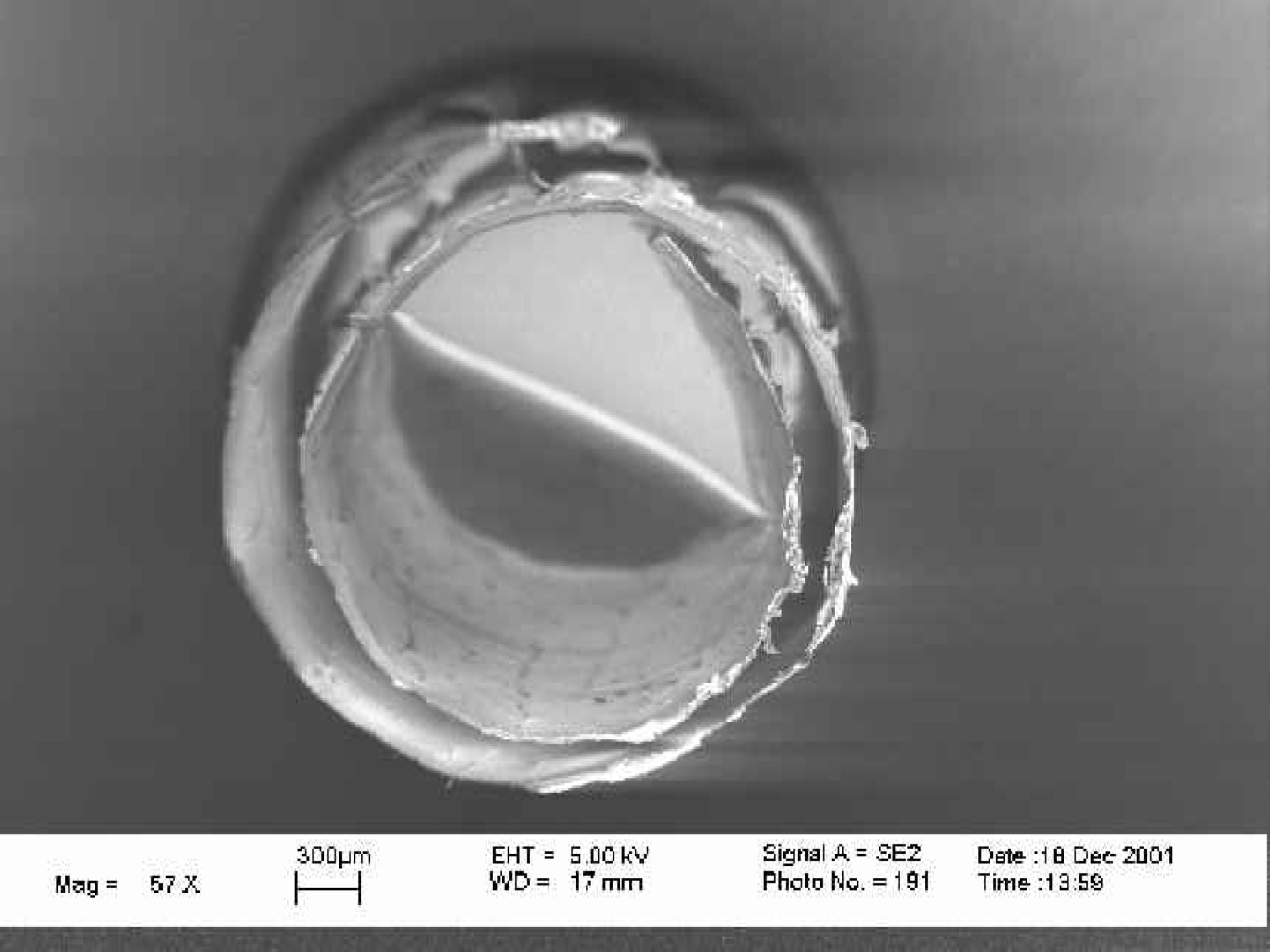
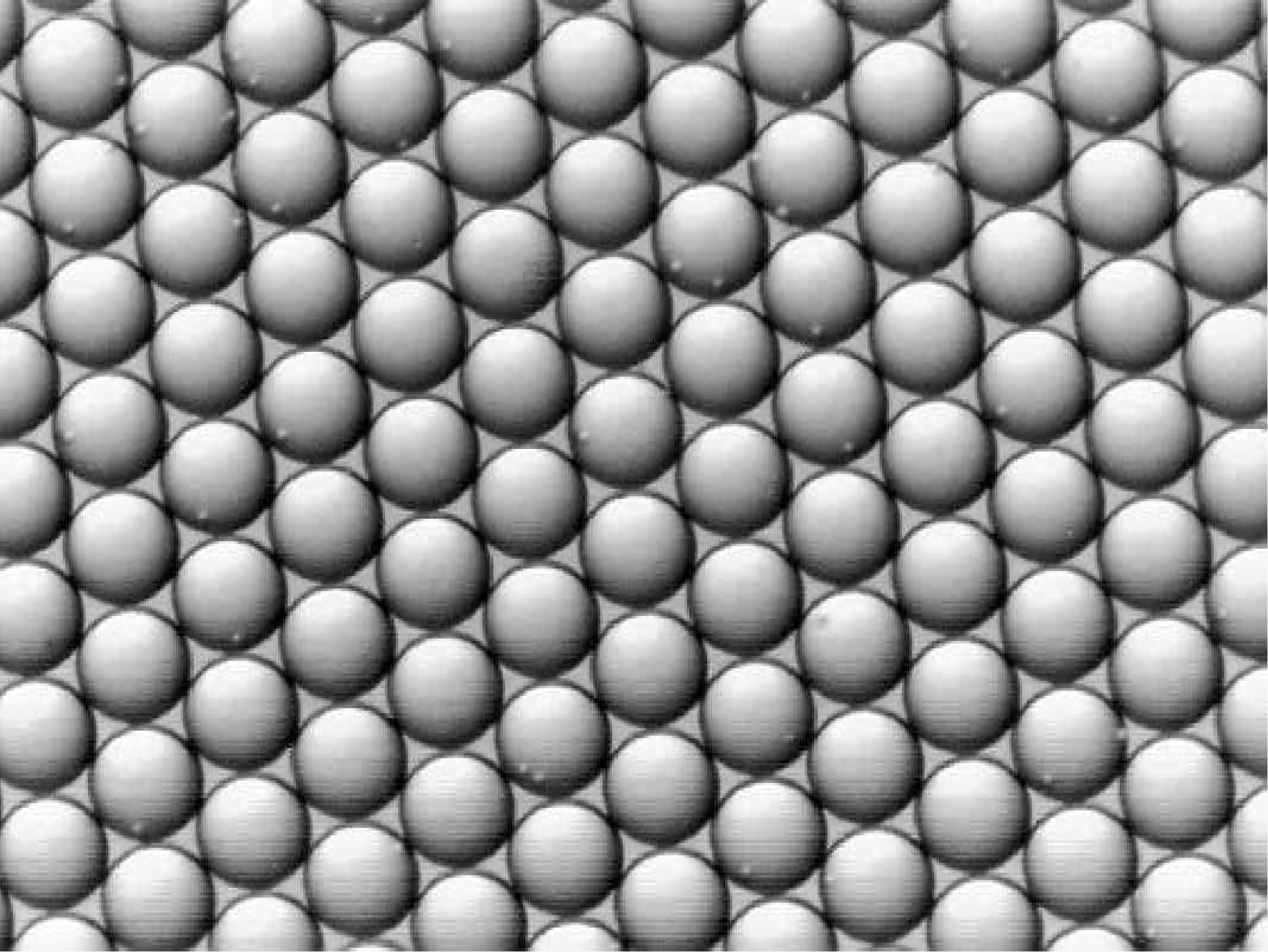
The same family of bioresorbable polymers used in creating structures for tissue growth can be loaded with small molecules, steroids, proteins, peptides, genetic material, etc., to be used as therapeutic agents (i.e., drugs). 23 24 Embedding these materials in the polymer allows for controlled release, with the polymer formulation and the geometry controlling the release profile. The simplest shape useful for drug delivery is spherical, which can be controlled to a very uniform diameter, or generated in a specific diameter distribution using ink-jet technology. Figure 9 shows microspheres created via ink-jet technology for the delivery of an anticancer agent.
SOLID SUPPORT CREATION AND MODIFICATION
In an application analogous to printing polymers for tissue engineering, other materials can be printed using ink-jet technology to create or modify solid support structures or synthesis sites for attachment of bioactive molecules. The localized control of wetting or reactivity and the creation of time-release flow obstructions can be obtained in a similar manner. Solid phase materials such as nitrocellulose, methyl cellulose, sol gels, and biotinylated PLGA have been dispensed onto substrates using ink-jet technology. Chromic acid has been used to modify polypropylene and acetone to modify polystyrene. Finally, cleavable linkers such as succinate and amidate have been dispensed.
CHEMICAL ANALYSIS
Ink-jet systems commonly contain functions other than the dispensing function. Filtration and temperature control are common, and fluid mixing systems have also been included. For biochemical analysis, the capture, concentration, and release of molecules of interest is a common function prior to analysis, usually involving mass spectroscopy. 25 Using an ink-jet device to perform this function may make the interface to chemical analysis MEMS devices simpler and smaller. MicroFab has integrated capture media into the single channel devices. The capture media in this device is C18, for the retention and concentration of peptides. Other capture media (e.g., C3, C4, C8, ODS, CN, TMS, HPL, MC, phenyldiisopropyl) can be integrated into ink-jet devices. MicroFab is currently developing both low-volume and array configurations.
PROTEIN ANALYSIS
The ink-jet device has the integrated capture media functions in a manner similar to traditional liquid chromatography. An elution solvent is used to release a sample, such as digested proteins, from the capture media over time resulting in a separation of peptides in relationship to their affinity to the retention media. The flow of the elution solvent is a function of dispensing drops from the inkjet device. This results in a time domain for conventional liquid chromatography (LC) being translated into the spatial domain, as in the case of performing MALDI-TOF (matrix-assisted laser desorption of ions - time of flight) mass spectroscopy (MS) analysis. Therefore, allowing both the separation and analysis of the sample using methods of MALDI-TOF MS. This compares to the discarding of samples and use of the more complex electrospray detection in conventional LC-MS.
Conductive polymer resistors printed using ink-jet technology, <200Ω/square, ∼1.0mm long.
MICRO ASSEMBLY
ELECTRONIC MATERIALS
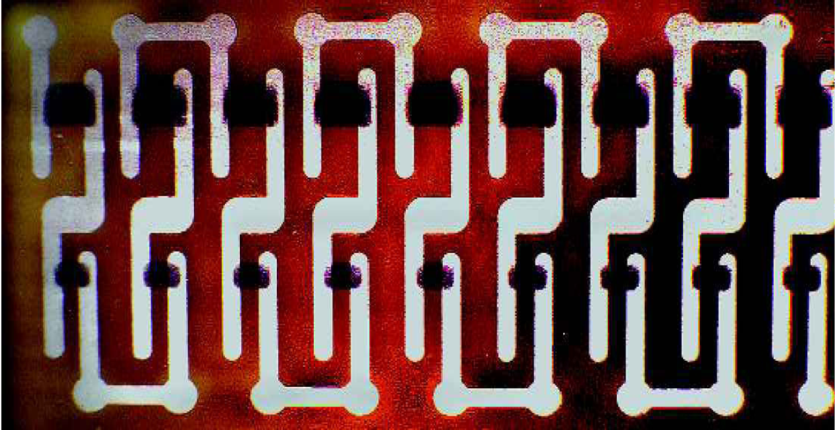
Solders have been dispensed using piezoelectric demand mode ink-jet technology. 26 27 Operating characteristics include: formation of spheres with diameters of 25–125μm; drop formation rates (on-demand) up to 1,000 per second; deposition onto pads at up to 600 per second; and operating temperatures up to 320°C. The solder dispensed has been primarily eutectic tin-lead (63Sn/37Pb), but a number of other solders have been demonstrated, including high lead (95Pb/5Sn), no lead (96.5Sn/3.5Ag; indium; 52In/48Sn), and low temperature bismuth solders. Figure 10 displays the results from printing solder onto an 18×18 test coupon with 100μm diameter pads on 250μm centers. The deposited solder volume is equivalent to a drop diameter of 100μm. Multiple drops of solder can be dispensed onto a single site. If the substrate is not heated, generally the solder drops will solidify before the impact of the next drop, producing a tower-like structure. Extension of this simple geometry into more complex 3-D shapes may be possible, but will be limited by how solidified drops are impacted by the wet solder drops.
Electrically conductive/resistive polymer solutions (aqueous and organic solvent based) have been dispensed to form embedded resistors on the inner layers of multilayer circuit boards. Figure 11 shows a portion of a test vehicle on an 18″x12” core sheet. Resistors ranging from 100Ω to several million Ω have been created using materials with resistivities as low as 200Ω/square.
Solder bumps ink-jet printed onto 100μm pads on 250μm centers at 400 per second.
PHOTONIC MATERIALS
Ink-jet technology has been used to “write” refractive microlenses, and waveguides 28 29 using optical epoxies, with the key advantage that they can be fabricated directly onto optical components of arbitrary geometry. 30 31 32 Refractive microlens configurations which may be printed using ink-jet processes range from convex/plano hemispherical, hemi-elliptical and square 33 to convex-convex. Arrays of thousands of microlenses have been inkjet printed for use as free-space optical interconnects in VCSEL-based photonic switches, 34 with 13,872 lenslets being printed on a single wafer. Hemi-elliptical and square microlenses have been created where adjacent drops are printed along one and two axes, respectively, and allowed to flow together prior to solidification and curing. The elliptical and square lens configuration could be useful in edge-emitting diode laser collimation and light-collection for detectors, respectively.
The process for printing multi-mode waveguides is similar to that utilized for hemi-cylindrical microlenses, except that the deposited optical material must be higher in refractive index than the target substrate. Arbitrary patterns of waveguides may be printed by utilizing software that enables precise adjustment of features, such as the number and location of branching points, turning radii and segment lengths, as shown in Figure 12. Edge smoothness of the guide-substrate interface is on the order of the wavelength of the transmitted light and it is superior to etched waveguides. To date, waveguides have been written only with materials having unacceptably high loss, but the use of low loss materials is under evaluation.
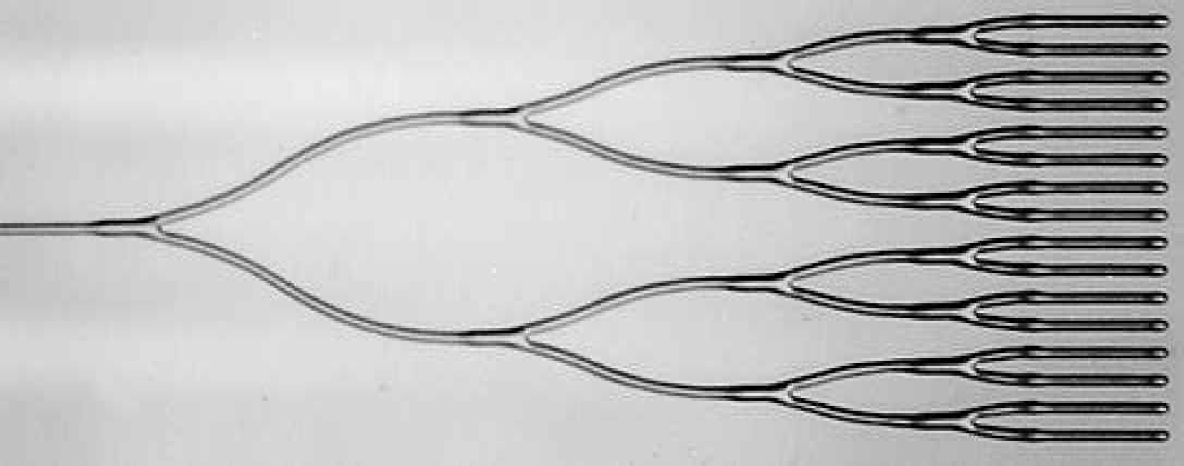
A 25mm long 1–16 branching polymer waveguide printed using ink-jet technology.
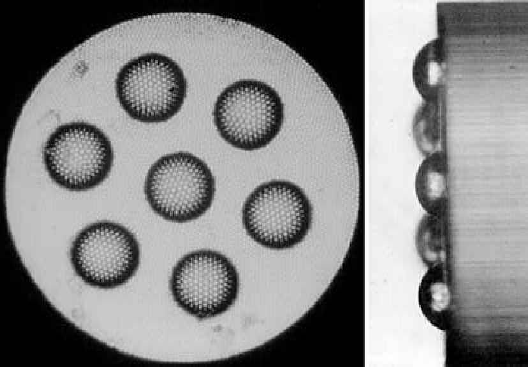
Chemical sensor materials can be ink-jet printed onto detectors for use in clinical diagnosis, 35 manufacturing process control, environmental monitoring, etc. UV-curing epoxies can be modified to be porous and doped with chemical indicators. These modified epoxies can be printed as sensor array elements onto the tips of imaging fiber bundles to provide a sensor configuration as exemplified by Figure 13.
Active optical materials printed with ink-jet technology have principally been used for display applications. Phosphor inks have been printed onto glass substrates as lines and arrays of spots, both with 90μm feature sizes. These printed features are smaller than pixels currently used in many phosphor displays, and have the high density and uniformity of particles in the pixels.
Light-emitting polymers are a subset of a broad class of conjugated polymers. To construct active devices with these materials, a uniform layer of approximately 1.0μm must be created in a structure, and the structure must create an electric field across the light-emitting polymer layer. Whether it is deposited in a spin-coating process or by ink-jet deposition, the polymer is usually suspended in low concentrations (0.5–2% by volume) in a volatile organic solvent, such as xylene. After deposition, the solvent is driven off and the polymer film is left behind. 36 MicroFab has demonstrated that feature sizes as small as 35μm can be achieved when printing light-emitting polymer solutions onto a surface coated with hole-injection layer material.
OTHER MATERIALS
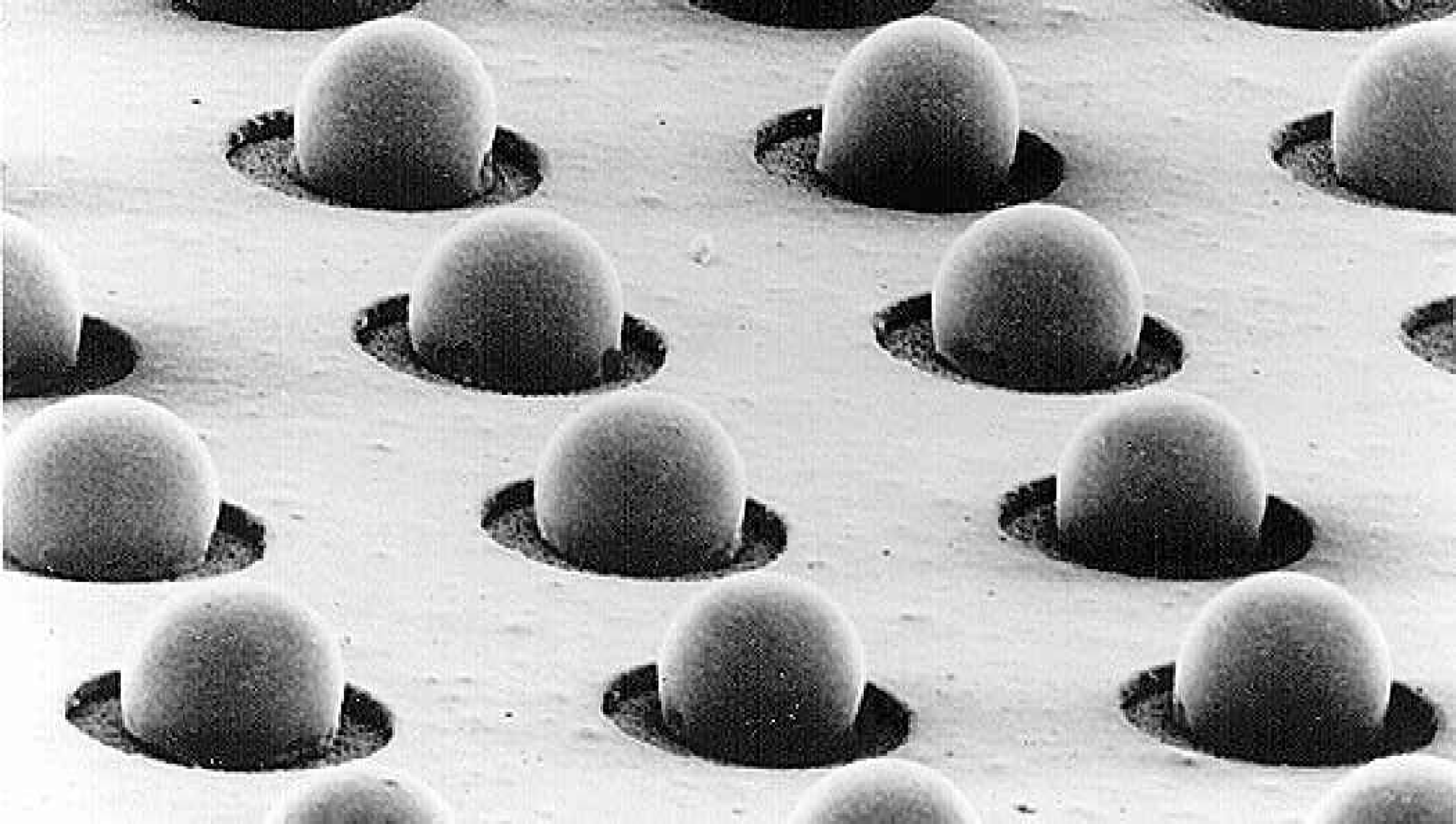
Adhesives for sealing and bonding can be ink-jet printed in simple line and dot patterns. In addition, complex patterns that vary both the spatial and volume distribution of adhesive can be printed. The same materials can be used for spacer bumps for flat panel display assemblies. Bumps as small as 25μm in diameter and 10μm high have been printed. Figure 14 includes an example of printed spacer bumps that would meet the physical and thermal (in excess of 200°C) durability requirements for flat panel displays.
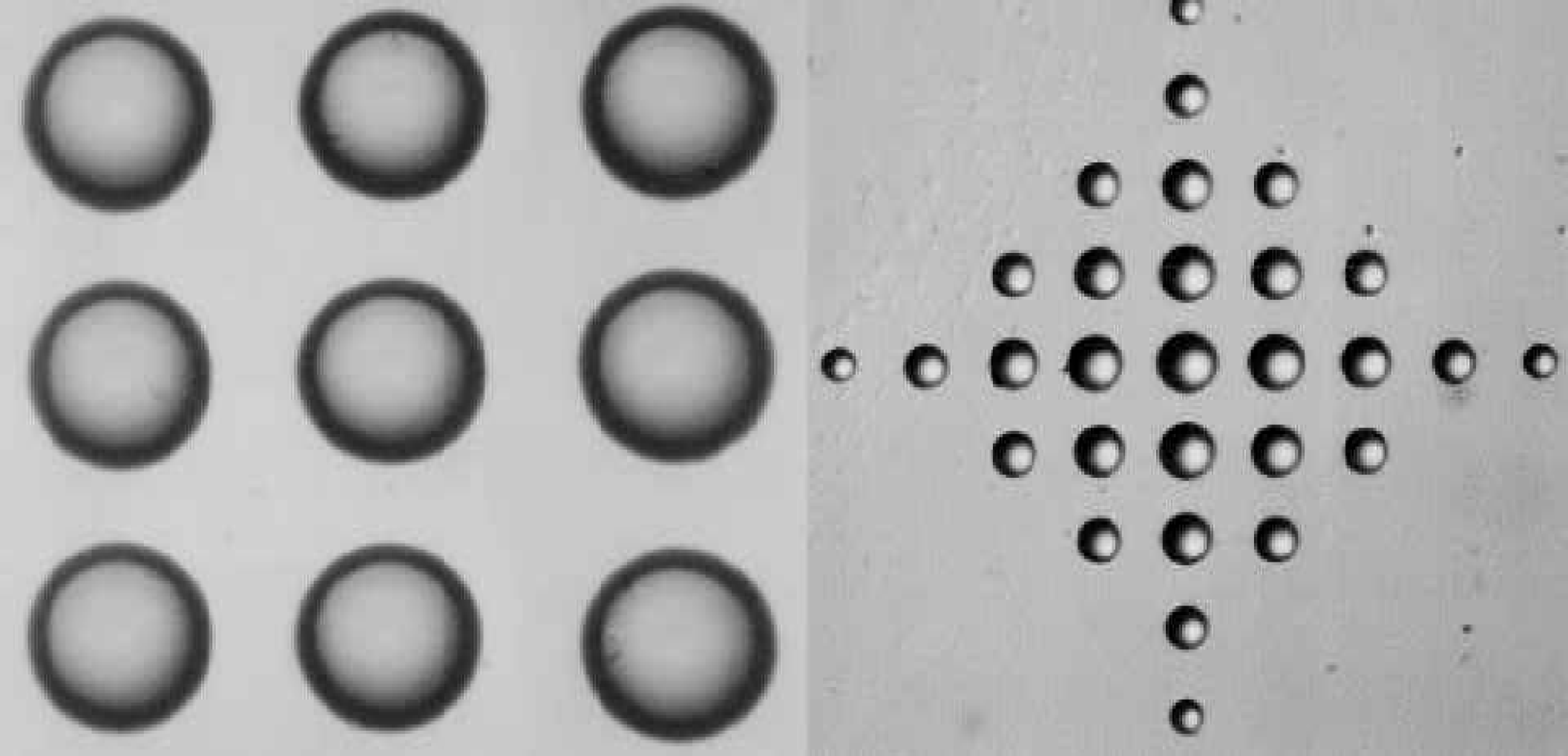
Left image, spacer bumps 95μm in diameter and 34μm high; right image, variable volume adhesive spots up to 80μm.
Summary
The capability of ink-jet printing technology to controllably dispense a wide range of materials of interest to MEMS and BioMEMS fabrication has been demonstrated. Materials dispensed include optical polymers, solders, thermoplastics, light-emitting polymers, biologically active fluids, and precursors for chemical synthesis. In addition to the wide range of suitable materials, the inherently data-driven nature of ink-jet printing technology makes it highly suited for both prototyping and flexible manufacturing.