
Abstract
Preparative Scale Supercritical Fluid Chromatography is emerging as a powerful alternative to HPLC for the purification and separation of complex chemical reaction mixtures. Advantages include greatly reduced solvent usage (and thus lower cost and environmental impact), higher throughput, and in some cases higher resolution. While there are commercially available prep SFC instruments, none currently offer all the features desired by many medicinal chemists engaged in the drug discovery process. These include: the ability to collect an unlimited number of fractions per sample with high recovery and negligible carryover, fully automated capacity to collect several hundred fractions, and the ability to collect fractions into the same disposable test tubes and racks which are already employed in HPLC. This article describes the customization of a preparatory scale SFC system purchased from Berger Instruments, Inc., Newark, DE. (a subsidiary Mettler-Toledo International, Inc., of Greifensee, Switzerland) in order to provide these capabilities.
INTRODUCTION
Compounds generated in any synthetic chemistry effort directed at drug discovery generally require purification before being provided to biological assay. Traditionally, the most efficient method of purification on a high throughput scale has been HPLC. Another analogous technique however, SFC, is available to the purification chemist which can offer advantages over HPLC.1––––5 SFC, like HPLC, involves the elution of compounds from a stationary phase column by a liquid mobile phase, but differs in that the primary mobile phase is a compressible liquid, carbon dioxide, and the columns a normal-phase type. Upon experiencing a pressure drop post-column, or just prior to fraction collection, the carbon dioxide reverts to the gas phase. This delivers purified sample dissolved in only minimal amounts of organic co-solvent, generally methanol, which can be more rapidly and more gently removed than the typical large volumes of aqueous organic solvent provided by RP-HPLC. Additionally, due to the low viscosity and high diffusivity of compressed carbon dioxide, higher resolution chromatography is sometimes achieved by SFC than by HPLC.1––3 Preparative scale SFC can be somewhat complementary to RP-HPLC. Very non-polar compounds can be separated, but the potential exists to purify a high percentage of polar compounds as well. Due to recent advances, preparative scale SFC is now beginning to realize its potential as a purification technique in drug discovery programs.2–––––17
An SFC system was desired that would be compatible with processes and HPLC systems already in place to serve the needs of medicinal chemists and high throughput organic synthesis clients of the high throughput purification group. The existing HPLC systems employ a protocol wherein peak collection is triggered by either UV or ELSD signal above a particular threshold, followed by MS validation. This philosophy is preferred over the more recently available MS triggered systems in that several chromatography instruments (four HPLCs in our case) feed into a single higher capacity, yet more expensive MS validation instrument.
This article details the customization of a commercially purchased prep scale SFC instrument that was procured from Berger Instruments, Inc., in mid-2000.
In order to satisfy the needs of internal medicinal chemistry clients we desired a Prep scale SFC instrument with the following capabilities:
Ability to collect an unlimited number of fractions per sample.
Collection into standard 18 mm × 150 mm (25 ml) collection tubes compatible with the racks (Gilson 44) and other post purification equipment currently used by our HPLC systems.
Fully automated fraction collection with on-board capacity to retain several hundred fractions per run.
Average recovery and carryover similar to that attained by HPLC.
Automated sample injection.
Robust and efficient peak detection.
Post purification results in a format compatible with existing chromatography data analysis and data base software.
While several vendors in addition to Berger offer commercially available systems, e.g., Gilson, Thar, Jasco, NovaSep, none met all the above needs.
It should be noted that in the time since this project was initiated Berger has added additional capabilities to their platform. Automated sample injection and fraction collection are now provided by a Cartesian style robot which has been integrated with the core unit. On-board capacity for 128 fractions is provided, and the peak detection module has been improved. However, fractions are collected under pressure in large, non-standard 50 ml vials. During collections the vials are enclosed in a special cassette which is pressurized to approximately 40 psig. After the fractions for a given sample are collected the robotic arm replaces the vials inside the cassette with fresh vials for the next sample. This system, while effective, imposes an upper limit of four fractions per sample. Because of these limitations the current Berger system would not have been suitable for our needs even if it were available when this project started.
SYSTEM OVERVIEW
Fig. 1 shows a block diagram of the completed system. The core of the instrument is based on the Berger Instruments, Inc., PrepSFC™ void of automated sample injection or fraction collection features. In order to provide all of the features desired, we have added an auto-sampling capability to the front end, a dual arm fraction collector coupled with a methanol wash system at the back end, and tied all components together with custom control software. In addition this software exports resulting SFC chromatography data in a format compatible with our existing HPLC database software. As a safety precaution all major components except the supply pumps and CO2 delivery system are housed in a transparent plastic enclosure which is ventilated into the building fume-hood exhaust system. CO2 is supplied at pressures and temperatures ensuring a liquid state via a refrigerated pumping system procured from Berger Instrument Company Presently, a separate computer is used for control of the fraction collector, autosampler, communication to and from the SFC control computer, and post run report generation (In the future, all communication and control will be merged into one computer).
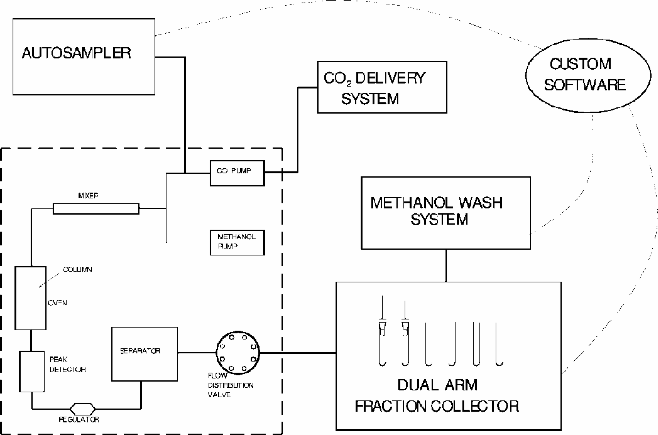
Schematic representation of completed system.
AUTOSAMPLER
Automated sample injection capability has been added in a straightforward manner by integrating a Gilson 232 autosampler into the system. The Gilson 232 is controlled through Gilson 720 software which allows programming with a suitable injection sequence. The autosampler bed can be configured to accept a wide variety of racks to accept sample plates or vials. In the current configuration, up to five racks of 44 samples in three ml or four ml vials can be loaded. Individual samples are aspirated from vials using a fixed pipette probe and loaded into the sample loop of a standard multi-port injection valve. This valve is plumbed into the stream from the methanol pump, in place of the standard Berger manual injection valve. Two-way communication is maintained between the autosampler and both the core SFC unit and fraction collector, by means of digital I/O signals. At the beginning of the cycle for each sample, the sample loop is loaded with sample. When signaled by an output signal from the SFC controller, the injection valve switches to connect the loop in series with the methanol stream and thus loads the sample onto the SFC column and commences the run. After the run is complete, as signaled by the SFC controller, the Gilson 232 returns a signal to the SFC controller to pause running of samples. The autosampler then switches the sample injection valve back to the load position and rinses the injection port and fixed needle with clean methanol, prior to un-pausing the SFC controller and commencing injection of the next sample.
FRACTION COLLECTOR
The development of a fraction collector capable of collecting at atmospheric pressure presented a number of engineering challenges. The goal was to enable collection of an arbitrary number of fractions per sample into the same standard disposable tubes (18 mm × 150 mm) and racks (Gilson 44) that are employed in existing HPLC systems. These needs imposed the following requirements:
The high flow of gaseous CO2 must be exhausted without significantly pressurizing the test tubes due to recovery and safety considerations.
Aerosolization of the compound laden methanol must be prevented or percentage recovery would be adversely affected by escape of methanol with the CO exhaust.
During collection the top of the tube should be covered to contain any aerosols or splashing that might contaminate neighboring tubes or the instrument deck.
Any collection nozzle must be quite compact to allow non-overlapping engagement of closely spaced, adjacent tubes.
The collection nozzles must be capable of rapid washing between fractions in order to eliminate carryover.
Any prospective collection system must always be in a “ready” state in order to collect the next fraction as it emerges from the column.
With these requirements in mind it was decided to pursue a two arm collection strategy. Utilizing two arms would make it possible to collect with one arm while the second arm is being washed and moved into position to collect the next fraction. This strategy was implemented by making use of a Cavro MiniPrep™ pipettor which offers two independently controllable probe arms. Each arm was outfitted with a specially designed “collection shoe” which was attached in place of the standard probe assembly. The collection shoes were then connected directly to the eight-way distribution valve included with the PrepSFC™ instrument (Fig. 2). Ports two and six are tied together and connected to collection arm “A” while ports four and eight are connected to collection arm “B”. Ports one, three, five and seven are connected to a waste manifold as found in the original Berger configuration.
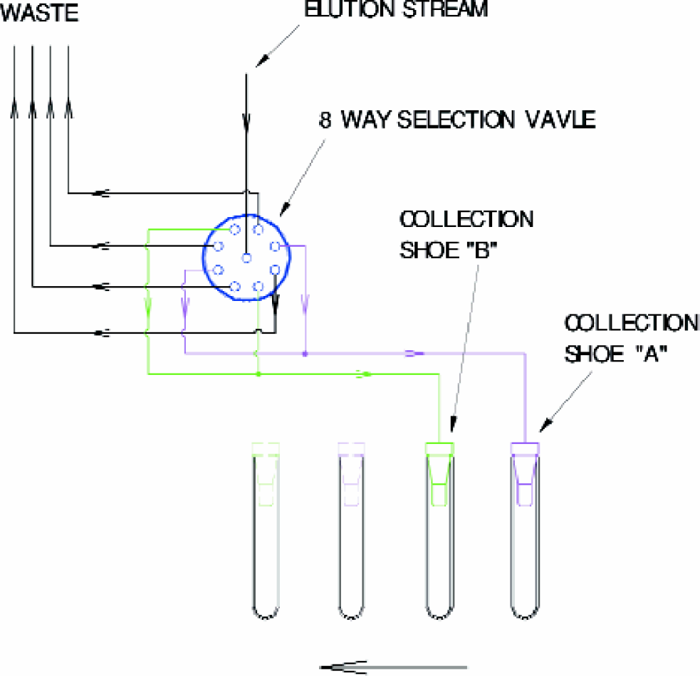
Schematic of two arm fraction collection system.
At the point of collection, both gaseous CO2 and a stream of methanol/compound solution enter the collection nozzle at high velocity. Decompression of CO2 from at or near supercritical conditions to atmospheric pressure results in up to a 500/1 volumetric expansion. Thus for a column flow of 50 ml/min., and 10% methanol, the volumetric flow rate of CO2 at the discharge point can reach 22.5 liters/min. Assuming 1.6 mm I.D. tubing, this equates to an exit velocity of approximately 190 meters/s and a marked tendency to aerosolize the compound/methanol stream. In order to thwart this effect the previously referred to “collection shoes” were developed (Fig. 3).
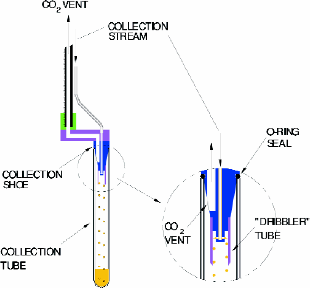
Collection shoe design.
The high velocity stream of CO2/methanol is channeled through the center of the shoe and split into four radial streams which impinge on the inside of a “dribbler” tube. As the stream impacts the inside wall of the dribbler tube most of the droplets of methanol coalesce into a low velocity stream of liquid which drips out of the dribbler and into the bottom of the collection tube. The remaining CO2 stream is forced through the annular space between the dribbler tube O.D., (9.5 mm) and collection tube I.D., (15.9 mm) and out a large vent in the side of the shoe. From there the flow is channeled via a connection bracket through the center of the Cavro “Z” arm drive mechanism, and eventually to the building exhaust system. The annular flow area formed by the dribbler tube O.D., and collection tube I.D., is approximately 65 times greater than that of the 1.6 mm I.D., tubing. Thus the average velocity of the exiting CO2 stream is only 1/65 that of its peak velocity in the tubing. It is presumed that most of the droplets that emerge from the dribbler tube are too large to be entrained by this much slower CO2 stream and therefore fall to the bottom of the collection tube. This simple design practically eliminates aerosol formation and allows nearly complete recovery of methanol from the CO2/methanol stream. Evidence that very little methanol aerosol escapes is provided by observation of the clear vinyl exhaust tubing which is used to exhaust the CO2. At no time has any noticeable liquid been observed in this tubing indicating that the exhaust stream is mostly dry CO2. Furthermore, we have measured recoveries approaching 100% when purifying chromatography-friendly compounds.
Pressurization of the collection tube is minimized by making the size of the CO2 escape channel as large as possible (approximately 3/16” I.D.). Actual measurements taken at 50 ml/min., flow rate, 95% CO2 indicate pressures within the collection tube of < 1 psig. An O-ring seals the collection shoe to the top of the collection tube to prevent leakage to the surrounding atmosphere. Under certain conditions adhesion between the O-ring and collection tube lip has caused the tube to be lifted as the shoe is raised. In order to defeat this tendency a small lateral “shake-off” move has been added to the shoe raise motion. Also, it is desirable to use higher durometer, inert O-ring materials such as Kalrez™ to minimize any sticking tendency. Photos of the fraction collector and collection shoe hardware are shown in Figure 4.

Photo of two arm fraction collector.

Photo of collection shoes.
WASH SYSTEM
A separate methanol wash system has been connected to the tubing for each of the two arms, at a point just downstream of the eight-way distribution valve. Fig. 5 shows the connection details for the “A” collection arm.
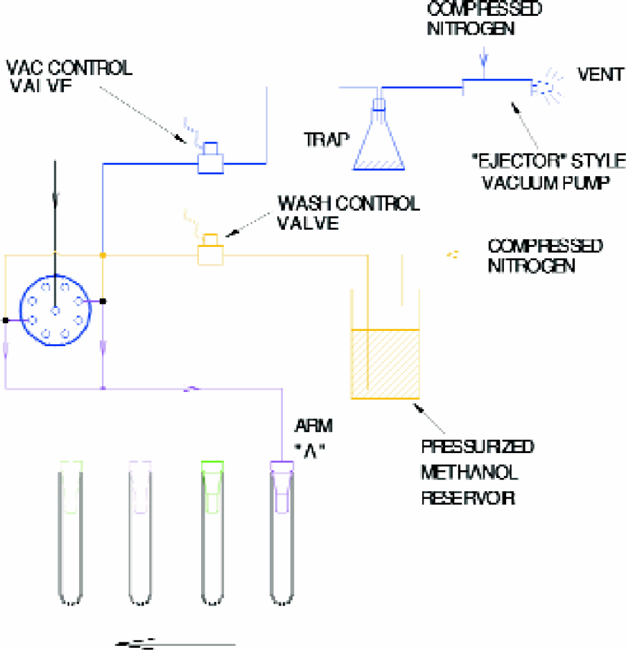
Schematic representation of wash system for collection arm “A”.
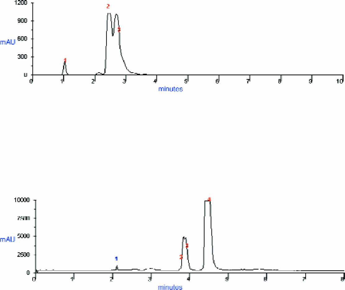
The need for a wash system is illustrated by Fig. 6a which shows the post purification HPLC chromatogram of a fraction collected using the SFC fraction collector with the wash system deactivated. Clearly the desired fraction is contaminated by residual compound left over from a previous fraction. The amount of carry-over has been found to be sample dependent, presumably due to the solubility of the specific compounds being purified. Figure 6 depicts typical results. Figure 6b shows the post purification HPLC chromatogram for the same sample collected with the wash system activated. No detectable carryover is observed.

Post purification HPLC chromatogram showing fraction collected with wash system deactivated. Carryover from a previous compound is clearly observed.

Post purification HPLC chromatogram showing same fraction collected with wash system activated. No significant carryover is observed.
Since there is no prior knowledge for how closely spaced any two adjacent fractions might be, it is important to perform all wash and move operations as quickly as possible. Figure 7 shows a timing diagram for the movements of the two collection arms. With this strategy the proper arm can nearly always be ready and in position in time for the start of the next fraction.
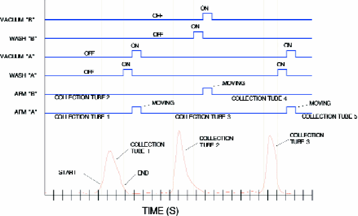
Timing diagram of two arm fraction collection system.
Fig. 8 shows the indexing pattern and the physical layout which enables the collection shoes to move one over the other in a serpentine path along the collection tube racks. The angle and offsets of the collection shoes relative to one another enables shoe “A” to cross over shoe “B” when necessary at the end of the tube column.
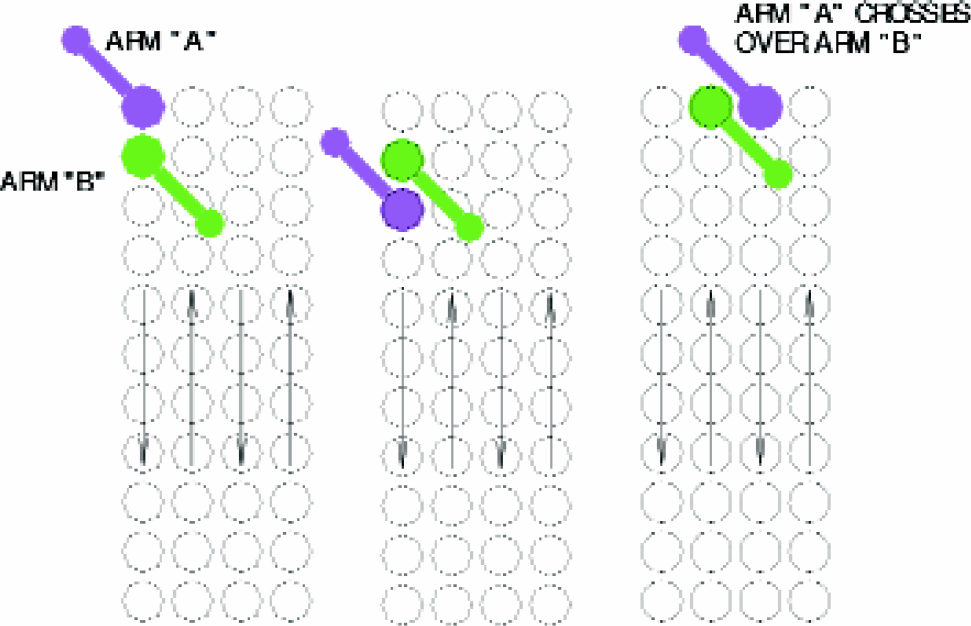
Physical layout of collection shoes and indexing pattern
RESULTS
The customized system has been in use within our High Throughput Purification group for more than a year. It is now the primary method for the purification of large numbers of compounds produced by our, High Throughput Organic Synthesis (HTOS), chemistry group. Presently the instrument is operated only during the day shift during which we routinely run 50–60 samples/day providing a capacity to purify approximately 300 samples per week. We eventually expect to double this number by performing fully automated overnight runs. Performance results are discussed below:
RECOVERY
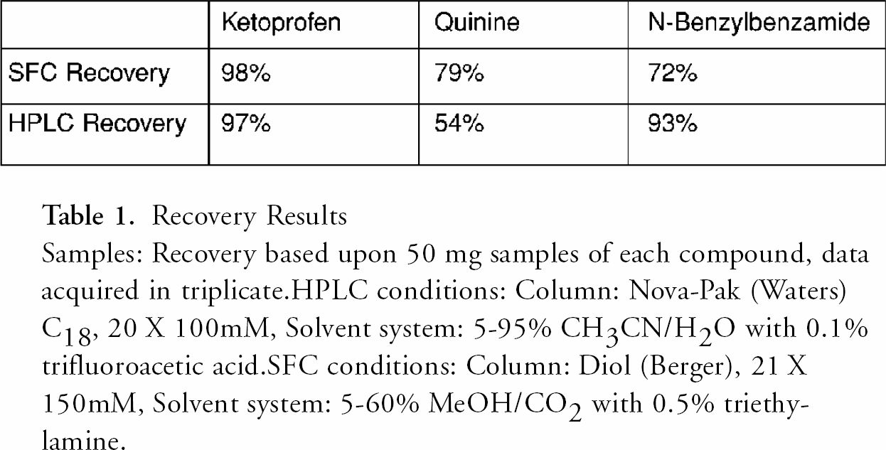
The recovery is comparable to results obtained by HPLC for chromatographically well behaved compounds, demonstrating that the collection shoe design is effective. It should be noted that in both preparative HPLC and preparative SFC, the total sample recovery is dependent upon how individual compounds retain on and elute from a specific stationary phase column with a specific mobile phase. Thus individual compounds will exhibit differing recovery yields on preparative HPLC vs. preparative SFC as different adsorption and desorption mechanisms are in effect as well as differences in column type and configuration. Typical results for a series of compounds are given in Table I.
Recovery Results Samples: Recovery based upon 50 mg samples of each compound, data acquired in triplicate. HPLC conditions: Column: Nova-Pak (Waters) C18, 20 × 100mM, Solvent system: 5–95% CH3CN/H2O with 0.1% trifluoroacetic acid. SFC conditions: Column: Diol (Berger), 21 × 150mM, Solvent system: 5–60% MeOH/CO2 with 0.5% triethylamine.
RESOLUTION
Carbon dioxide at the temperatures and pressures at which it is employed in preparative scale SFC is a low viscosity and high diffusivity liquid. Therefore higher mobile phase flow rates along with longer stationary phase columns can be employed for the separation of components from a mixture. This leads to the possibility of achieving increased resolution for SFC relative to HPLC separations, at least in some cases. As an example, the separation of two amine containing compounds, traditionally difficult to separate components, are depicted by Figure 9a and Figure 9b.
SFC separation of 25 mg each of (Quinine & 1-(4-methylphenyl)-2-methylpiperazine. Column: Aminopropyl (Berger), 21 × 150 mmGradient: 5–60% MeOH (with 0.5% Triethylamine)/CO2
RELIABILITY
Since activation the system has been utilized successfully to purify thousands of drug compound mixtures. In spite of this achievement overall system reliability has at times been an issue. As is typical for newly developed equipment, we have experienced challenges in maintaining a steadily functioning system. Initially instabilities in the user interface and control software caused repeated disruptions. Revisions to the software and the installation of a faster computer have largely solved these problems. More recently, mechanical glitches have created stoppages. These have included malfunctioning of the back-pressure regulator, inadequacies in the original UV detector, and tangling of the tubing used within the two arm fraction collector. The back-pressure regulator and UV detector problems were solved by installation of upgraded components supplied by Berger. Tube tangles occurred because each of the collection arms possesses two flexible tubes -one delivering eluent and a second, larger tube for CO2 exhaust. As the arms move independently past one another there is a tendency for the different tubes to snag. The problem was resolved by re-routing the CO2 lines away from the eluent lines, upward and through the top of the instrument enclosure.
A surprising source of trouble has come from chemical attack of the Viton™ elastomers present in the valves and fittings used throughout the methanol wash system. Repeatedly these seals have swollen to the point that they broke apart and created blockages in critical fluid passages. This occurred despite the fact that Viton™ is rated excellent for methanol service in many chemical compatibility tables. Possibly the combination of methanol and CO2 caused the attack (It has since been learned that silicone rubber elastomers are a better choice in this environment. Another excellent choice, albeit expensive, is Kalrez™).
It is important to note that these types of problems are not unexpected in a newly developed instrument and do not dampen our enthusiasm for the technology. System reliability is now adequate and certain to improve further as experience with the system is gained.
CONCLUSION
The customization of a Berger Instruments PrepSFC™ has been largely successful. Through the modifications described we have developed an SFC capability that provides a powerful complement to HPLC and overcomes the limitations of the original purchased instrument.
Thus far, of the first 20 sample sets and 20 pilot reactions submitted for purification by the HTOS group, ∼30 were both amenable to SFC and gave superior resolution by SFC, therefore we would predict ∼75% of our compounds could potentially be purified by SFC. This would require additional systems which are not in place today. However, we see many advantages in increasing the role of SFC. The time savings alone are attractive-our cycle time is approximately six minutes per compound using SFC vs. 12 minutes for HPLC. Although not universally true, resolution is sometimes higher than that possible by HPLC. In many cases we have separated compounds which could not previously have been resolved. And perhaps most importantly, we are enjoying very significant environmental benefits. The volumes of organic solvent consumed per compound have been approximately one half that consumed by our HPLC instruments. Furthermore, the pure methanol waste generated from SFC is much easier to dispose of and the cost is lower. Pure methanol can simply be burned while the much greater volumes of acetonitrile/water left over from HPLC are classified as hazardous waste and must be disposed of accordingly. And the SFC fractions, having been collected in relatively small amounts of pure volatile solvent can be more “gently” dried as compared to the acetonitrile/water mixtures typical in HPLC.
One limitation with our implementation of preparative SFC is a lack of analytical SFC instrumentation at present. This has required that we optimize SFC purification methods on a compound type basis rather than by analytical data. It should be noted however, the collection in both analytical HPLC and preparative SFC of two UV wavelengths data allows a quick visual identification of the most likely peak or few peaks desired, thus post-purification validation by MS generally involves only 1–2 MS acquisitions per sample to identify the desired component.
In summary it is a safe bet that the role of SFC, with its demonstrated advantages, will continue to expand at Abbott Laboratories. As our understanding of SFC chromatography grows, and equipment reliability issues are resolved, we expect purification of novel chemical compounds by SFC to play an increasingly significant role in our drug discovery programs.
ACKNOWLEDGEMENTS
The authors would like to thank the Abbott Corporate Development Shop for the fabrication of all custom mechanical components incorporated within the system and the SFC team at Berger Instrument Co., for their advice and assistance throughout the project.
TRADEMARKS
MiniPrep™ is a registered trademark of Cavro Scientific Instruments, Inc.
Viton™ is a registered trademark of Dupont Dow Elastomers. PrepSFC™ is a registered trademark of Berger Instruments.