
Abstract
INTRODUCTION
Improvised explosives have been used in recent terrorist bombing activities. These home-made explosives generates significant amount of inorganic ions, such as ammonium, methylammonium, potassium, sodium, perchlorate, chloride or nitrate. 1,2 Such explosives and explosive residues are frequently analyzed using ion-chromatography (IC) or capillary electrophoresis (CE) systems. 1–––4 However, these laboratory-based methods are not field portable, nor can they analyze relevant samples within extremely short (<30 sec) time scales. Therefore, fast-responding field-deployable analytical systems are desired for monitoring ionic (“low-energy”) explosives at the sample source. Lab-on-a-chip technology offers great possibility for obtaining the desired forensic information in a faster, simpler, and cheaper manner compared to traditional laboratory-based instruments. 5
This paper describes a microchip capillary electrophoresis with an integrated contactless conductivity detection system in connection to a low-energy explosives detection. The new contactless conductivity microchip detector is based on placing two planar sensing aluminum-film electrodes on the outer side of a microchip (without contacting the solution) and measuring the impedance of the solution in the separation channel. The contactless route obviates problems (i.e., fouling, unwanted reactions) associated with the electrode-solution contact, offers isolation of the detection system from high separation fields, and greatly simplifies the detector fabrication. 6––8 Relevant experimental variables, such as the frequency and amplitude of the applied ac voltage were examined and optimized. The detector performance was illustrated by the separation of low-explosive ionic components, such as the potassium, sodium, ammonium and methylammonium cations and the nitrate, perchlorate and chloride anions.
EXPERIMENTAL
APPARATUS
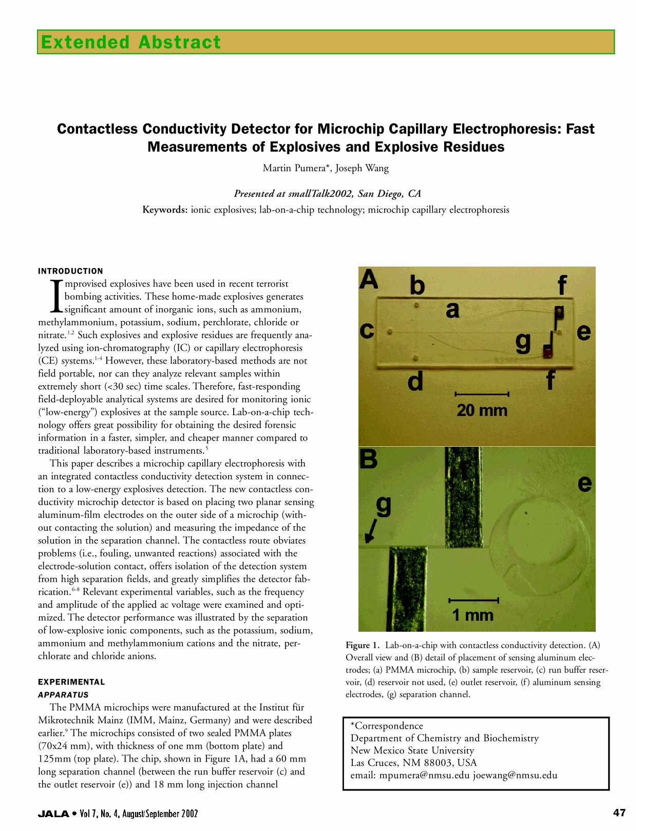
The PMMA microchips were manufactured at the Institut für Mikrotechnik Mainz (IMM, Mainz, Germany) and were described earlier. 9 The microchips consisted of two sealed PMMA plates (70×24 mm), with thickness of one mm (bottom plate) and 125mm (top plate). The chip, shown in Figure 1A, had a 60 mm long separation channel (between the run buffer reservoir (c) and the outlet reservoir (e)) and 18 mm long injection channel (between the sample reservoir (b) and the unused reservoir (d)). The two channels crossed each other halfway between the sample and the unused reservoir and nine mm from the run buffer reservoir. The channels had a 50 μm × 50 μm squared cross section. A Plexiglas holder was fabricated for accommodating the separation chip. Short pipet tips were inserted into each of the four holes on the PMMA chip for providing solution contact between the channel on the chip and corresponding reservoirs on the chip holder.
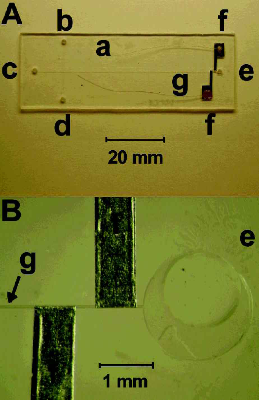
Lab-on-a-chip with contactless conductivity detection. (A) Overall view and (B) detail of placement of sensing aluminum electrodes; (a) PMMA microchip, (b) sample reservoir, (c) run buffer reservoir, (d) reservoir not used, (e) outlet reservoir, (f) aluminum sensing electrodes, (g) separation channel.
Fluid control was accomplished by applying the selected voltage to the corresponding reservoirs. After initial sample loading in the sample arm, the samples were loaded by applying potentials +83 V/cm between sample reservoir (b) and outlet reservoir (e) for three second (injection of cations). Potential −83 V/cm was applied between reservoirs (b) and (e) for two seconds when anions were injected.
The rectangular-shaped electrodes (0.7 mm × 10 mm) for contactless conductivity detection were fabricated from two 10 μm-thick aluminum-foil strips. The end side of the electrode was widened to four mm to facilitate the electrical connection. The electrodes were fixed from the outside to the 125 μm-thick PMMA cover plate of the microchip using a common epoxy, at a distance of 100 μm from the end of microchannel. The thin copper wires (0.1 mm diameter, 30 mm long) were attached to the electrodes using a conducting epoxy and were tin-soldered to the detector electronics. The electrodes were separated by 350 μm distance and were placed in an “anti-parallel” orientation to minimize the stray capacitance between them (Figure 1B). 7 The circuitry was designed in accordance with a previously reported scheme. 6,10 This scheme allows convenient interface to data acquisition systems (a computer DAQ or a chart recorder). The electronic circuit was placed in a shielded box to protect it from external electric fields. The open side of the box was placed (on the chip) as close as possible to the sensing electrodes, so that the box acted also as a shield for the electrodes. Further minimization of the noise was achieved by securing the chip (along with the printed electronic board) from possible mechanical vibrations. A HP 8116A function generator (Hewlett-Packard, Palo Alto, CA) was used for generating the ac signal (usually a sinus waveform with a frequency of 200 kHz and peak-to-peak amplitude of 5Vp-p).
CONCLUDING REMARKS
Figure 2 shows typical electropherograms obtained with the CE-microchip contactless conductivity system for mixtures of post-blast cations [A; ammonium (a), methylammonium (b), potassium (c) and sodium (d)] and post-blast anions [B; chloride (a), nitrate (b) and perchlorate (c)]. Due to favorably low electroosmotic flow in PMMA microchip device μEOF = 1.06 × 10⁻⁴ cm 2 /Vs, in our case), the cation and anion separation was performed in the cathodic (separation field of +500 V/cm) and anodic modes (separation field of −500 V/cm), respectively, using the same run buffer, without adding an electroosmotic-flow reversor. All cations and anions display well-defined and resolved peaks. The half-peak width ranges from 0.6 s (ammonium) to 1.2 s (nitrate). Such a defined response, coupled to the low noise level, offers convenient quantification of these micro- and millimolar levels of studied ions. The total analysis of cations is 25 s, while the analysis of anions is completed within 20 s; accordingly, all seven explosive-related cations and anions can be rapidly measured within a total run time of 50 s. Such short assay times are extremely attractive for providing early and timely detection of low-energy explosive residues.
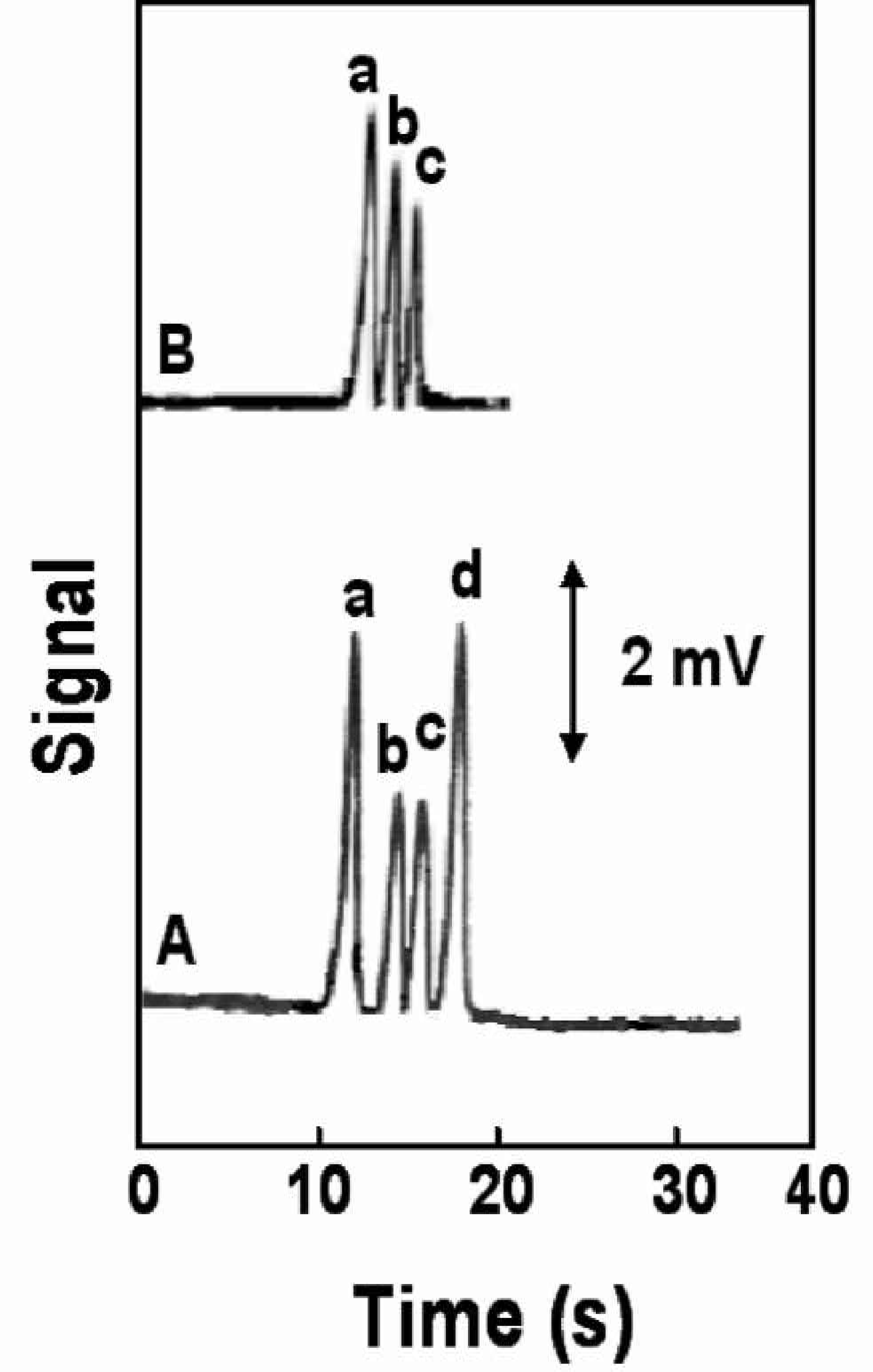
Electrophoregrams showing the separation of post-blast model mixture of cations (A) and anions (B) using electrophoresiss microchip with contactless conductivity detection. A: 350 μM ammonium (a), 350 μM methylammonium (b), 350 μM potasium (c) and 600 μM sodium (d) B: 800 mM chloride (a), 800 μM nitrate (b), 600 μM perchlorate (c) Conditions A: Separation field strength +500 V/cm; injection field +83 V/cm, 3s; detector frequency 200 kHz; detector peak-to-peak amplitude 5 Vp-p; MES/His buffer (20 mM, pH 6.1) containing 7.5 mM 18-crown-6 ether (for separation of potassium and ammonium ions) as the run buffer. Conditions B: Separation field strength −500 V/cm; injection voltage −83 V/cm, 2 s, other conditions, as in Figure 2a
Experimental parameters affecting the detection of explosive-related ions were evaluated and optimized. The response of contactless conductivity detector is strongly dependent upon the frequency and amplitude of the applied ac voltage. 11 The influence of the applied frequency of ac voltage was studied over the 50 kHz to 1000 kHz range for a sample containing ammonium and methylammonium ions. Both explosive-related cations exhibit a similar trend. The response increases slowly between 50 and 400 kHz, then more rapidly (reaching the maximum at 700 kHz) and decreases sharply at higher frequencies. Unstable response peaks were observed over the 400–900 kHz range. It is clear that low frequencies lead to more favorable signal-to-noise characteristics and a well-defined response. The exact reason for the fluctuations observed at high frequencies is not fully understood in view of the complex nature of the registered high-frequency impedance signal. It can be attributed to the complicated equivalence circuit of the detection cell. 6 All subsequent work employed a frequency of 200 kHz which offered the most favorable response characteristics.
The influence of the peak-to-peak amplitude of ac voltage (Vp-p) upon the ammonium and methylammonium signals was studied in 0–10 Vp-p range. The response increases linearly over the range 0–5 Vp-p and starts to level off afterward. Such amplitude change results also in a nearly linear increase of the noise level. The most favorable signal-to-backround characteristics were obtained using a voltage of 5 Vp-p.
The contactless conductivity microchip detector displays a well-defined concentration dependence for both cationic and anionic explosive-related species. The favorable analytical characteristics are summarized in the table 1. Limits of detection favorably meets the needs of pre- and post-blast analysis of explosives. 1 However, for point-of-analysis of surface wipes would be beneficial lower limits of detection (i.e., achieved by preconcentation using izotachophoretic focusing; currently under investigation in our laboratory), (REF #3). The new microchip CE/contactless conductivity system is characterized also with good reproducibility and stability. For example, series of 12 repetitive injections of a mixture containing 350 μM ammonium and nitrate ions resulted in standard deviations of mean 16.1 and 19.9 μM, respectively. The stability of the response is associated with the absence of unwanted surface-passivation reaction associated with the contactless configuration of detection electrodes.
Calibration Parameters of Ammonium and Nitrate using PMMA-CE microchip device with contactless conductivity detector.
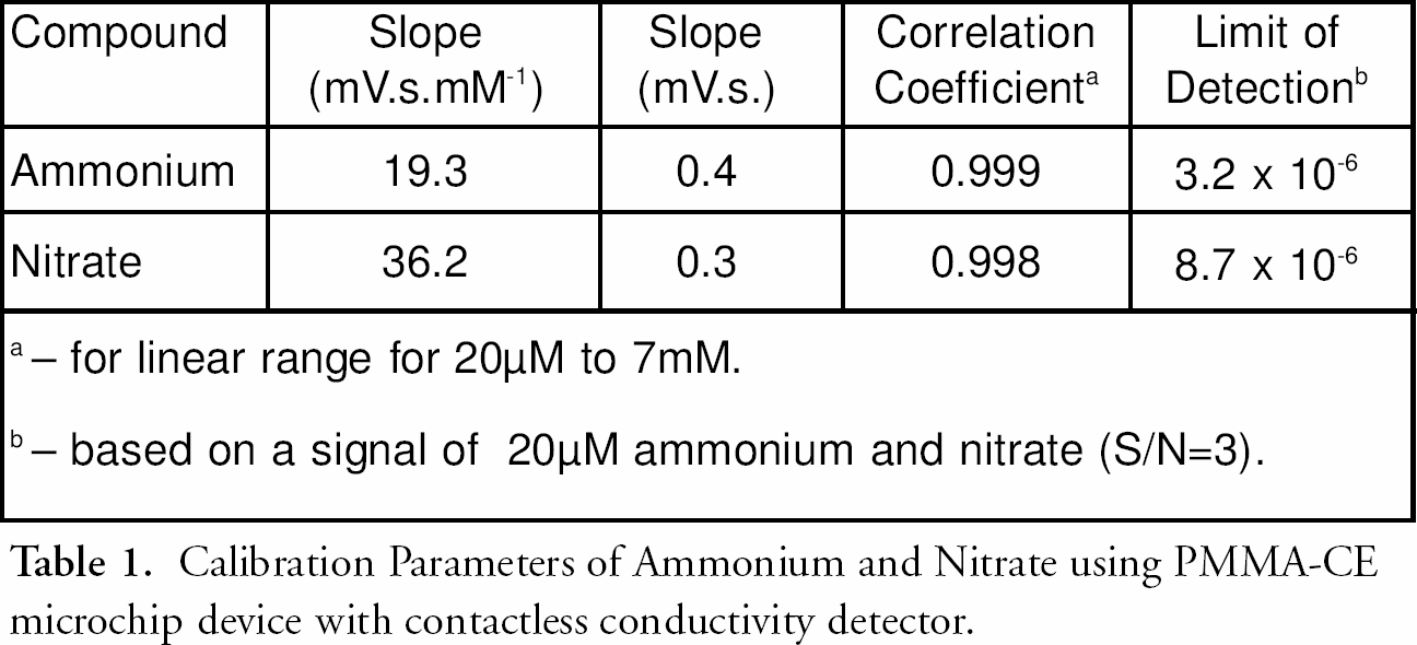
— for linear range for 20μM to 7mM.
— based on a signal of 20μM ammonium and nitrate (S/N = 3).
In conclusion, we have demonstrated a microchip electrophoresis — contactless conductivity system for the fast separation and detection of explosive-related ions. The new microfluidic device offers significant advantages in terms of high-throughput, low-cost, miniaturization/portability. Such rapid identification of inorganic explosive residues should have a major impact upon the protection of first responders, and upon the prevention of terrorist activity.
Present activity of our laboratory is focused on improvements of electrode configuration and electrode microfabrication (screen-printing or lithography), which would allow mass-production of this type of detector. We are also developing a continuous sampling capability.
ACKNOWLEDGMENT
This research was supported by grants from the U.S. Dept. of Justice-MIPT Program and the U.S. Office of Naval Research (Award Number N00014–02–1–0213). The authors would like to thank Drs. F. Opekar and I. Jelinek (Charles University, Czech Republic), for valuable discussions.