
Abstract
Microfluidic technologies have been applied extensively in rapid sample analysis. Some current challenges for standard microfluidic systems are relatively high detection limits, and reduced resolving power and peak capacity compared with conventional approaches. The integration of multiple functions and components onto a single platform can overcome these separation and detection limitations of microfluidics. Multiplexed systems can greatly increase peak capacity in multidimensional separations and can increase sample throughput by analyzing many samples simultaneously. On-chip sample preparation, including labeling, preconcentration, cleanup, and amplification, can all serve to speed up and automate processes in integrated microfluidic systems. This article summarizes advances in integrated multiprocess microfluidic systems for automated analysis, their benefits, and areas for needed improvement.
Keywords
Introduction
Microfluidic analysis systems have advanced rapidly since the early 1990s, 1,2 providing new capabilities for chemistry, biology, and medicine. For instance, microfluidic devices offer low sample and reagent consumption 3 (which is critical for expensive pharmaceutical characterization or trace samples), small dead volume, 4 fast mixing, 5 –7 rapid analysis speed, 8 high throughput, 9 and valveless flow control. 10 Consequently, these advantages of microfabricated devices have been exploited widely in bioanalysis, and reviews cover areas such as protein separation, 2,11 cell analysis, 12 –14 genomics, 15,16 and biomarker assays. 17,18 Because the field of microfluidics has become so broad, our focus here is on integrated microfluidic methods in separation-based analysis with strong automation potential.
To date, many microfluidic designs have been made, but they are generally tested with low-complexity samples. For actual biological specimens, which are mixtures with wide analyte concentration ranges, it remains a challenge to directly separate even tens of components on microdevices. The small microchip platform size usually results in a short separation length, limiting the resolving power and peak capacity, which are critical for separating complex mixtures. 19 For instance, the peak capacity of a polydimethylsiloxane (PDMS) microchip for micellar electrokinetic chromatography (MEKC) was ∼ 12 for protein separation. 20 Importantly, to completely isolate a 20-component mixture with 95% probability, the peak capacity must be ∼ 800. 21 Clearly, resolving power and peak capacity in microfluidic systems could be improved. In addition, tiny sample volumes (usually in the microliter range) 22 are placed on microdevices, and often nanoliter or smaller volumes are injected. Furthermore, microchips generally have a short optical detection path, 23 such that the detection limit is another aspect of microfluidic devices that could be improved.
Fortunately, these separation and detection limitations can be overcome by integrating multiple functions and components at the chip scale. Methods for microfluidic device fabrication are generally based on photolithographic processes, which make complex designs possible. 24 Moreover, fabrication techniques have been developed to transfer these complex designs into low-cost materials like plastics. 25,26 By integrating sample preparation processes into a single microdevice, trace samples can be preconcentrated before analysis. Multidimensional separations on-chip can significantly improve the sample capacity. Importantly, because the samples in many integrated microdevices are manipulated by voltages, these microfluidic systems can be readily automated. Compared with traditional methods, automated sample analysis can be more economical, requiring less human intervention, and enabling increased sample throughput. 27 Consequently, these advantages make integrated microdevices especially attractive for automating the characterization of complex mixtures.
Because the applications and principles of integrated microdevices have been reviewed elsewhere, 2,24 we focus this review on integrated microfluidic methods with high potential for automating analysis. Multiplexed separation and on-chip sample preparation will be emphasized in this work. We note that on-chip sample preparation is a broad topic, encompassing cell analysis, 14 sample purification, 28 and other technologies. Hence, to provide an in-depth discussion, we limit the scope of this review to the sample preparation areas of labeling, preconcentration, and polymerase chain reaction (PCR) amplification.
Multiplexed Separation
Multidimensional Systems
Because the overall peak capacity of multidimensional separations is the product of the peak capacities of the individual, orthogonal one-dimensional methods, 29,30 these systems are of great interest for complex mixture analysis. For example, two-dimensional gel electrophoresis (2DE) is an established approach for high-resolution profiling of proteins, 31 separating analytes according to isoelectric point in the first dimension (isoelectric focusing [IEF]) and then by mass-to-charge ratio in the second dimension (polyacrylamide gel electrophoresis [PAGE]). Despite its enormously successful application in biochemistry and clinical studies, 32 the downsides of 2DE are also significant: extensive hands-on labor (gel preparation, staining, etc.) and slow separation (∼1 day). 33 To increase throughput and facilitate automation, 2DE has been transferred into a microfluidic platform. For instance, MEKC coupled with capillary electrophoresis (CE) was demonstrated for peptide separation in 2000. 34 However, this approach used different buffers for the two dimensions, which in turn increased the complexity of device operation. More recently, Herr et al. 30 developed a microchip IEF—CE system that used the same buffer for both dimensions. Microchip IEF—PAGE systems have now been automated, providing a separation time of < 2 h. 35 Another approach for 2DE involves using a gel for the first dimension and a solution electrophoresis method for the second dimension, as implemented by Osiri et al. 36 with a capillary gel electrophoresis—MEKC system that was used to profile fetal calf serum proteins. Chen and Fan 37 recently reviewed two-dimensional microchip separations, and the reader can refer to this reference for additional information.
Future multidimensional electrophoresis microdevices will need to further increase peak capacity through more effective coupling of separation dimensions. Improvements to device fabrication and operation should enhance the interface between the first and second separation techniques, potentially providing additional information.
Parallel Separations
Although multidimensional separations can increase peak capacity, usually only one sample is analyzed per run. Sample throughput or capacity can be increased by performing separations in parallel columns, in a manner similar to what is done in slab gel electrophoresis. In a microchip format, forming parallel capillaries is readily achieved via photolithographic patterning. The first capillary array system for microchip electrophoresis was demonstrated in 1997 with 12 separation channels in parallel (Fig. 1A). 38 In this design, channels terminate at one anode reservoir, whereas the other end of each lane has a cross-injection design with three reservoirs; this device was successfully used in human HLA-H genotyping. Mathies' group further explored a 48-channel design with 96 sample reservoirs. 42 The unique rectilinear layout facilitated sample loading via a multichannel micropipettor. However, detection constraints made scaling to more channels difficult; moreover, in this design, two samples shared one separation channel, which increased the possibility of cross-contamination.
Because of the limitations of the rectilinear format, a radial microplate design with 96 channels was developed. 43 The radial design used a rotary confocal fluorescence scanning system to probe each channel. Importantly, with an increase in wafer size, more lanes or longer separation channels could be obtained. For instance, 384 lane microchip DNA analyzers were constructed in 8-in. (200-mm)-diameter substrates (Fig. 1B). 9 Separation length and resolution are somewhat limited in the radial design; a 6-in. (150-mm)-diameter wafer only offers a 5.5-cm separation length, 44 which is not ideal for DNA sequencing. For a fixed device size, the separation length can be increased by folding the channel in a serpentine fashion. However, because the inside track of a turn will be shorter than the outside track, a“U”-shaped turn will cause band dispersion, reducing resolution. Paegel et al. 45 found that this dispersion can be significantly reduced by narrowing the width of a channel in a turn, which extended the separation length to ∼ 16 cm on a 6-in.-diameter wafer, yielding an average sequencing read of 430 bases. 46 Recently, Kumagai et al. 39 developed a microfabricated DNA sequencing device with 384 lanes in a fan shape (Fig. 1C). The microplate formed a part of a much larger automated apparatus that yielded a throughput of 5 × 10⁶ bases per day per instrument.
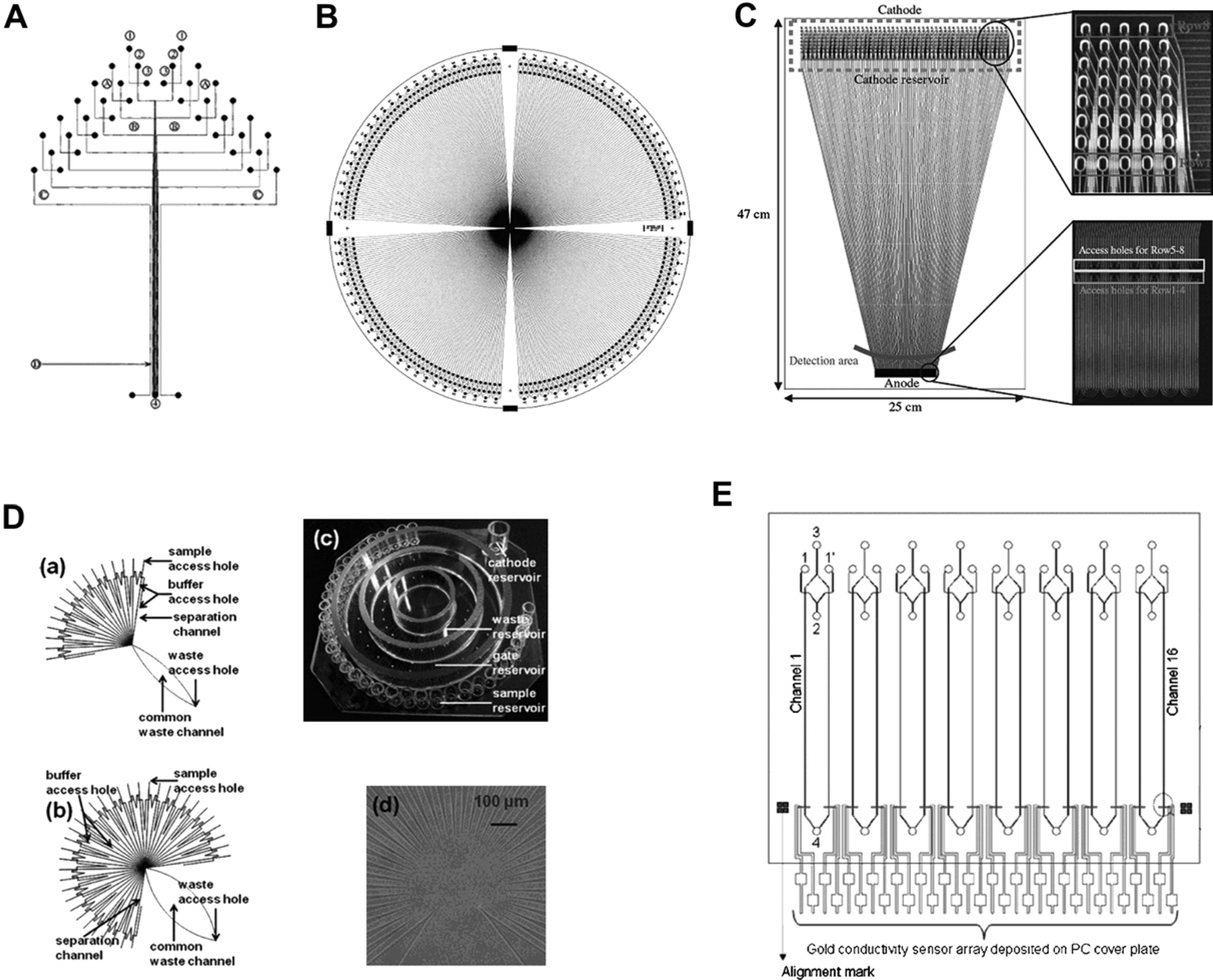
Parallel separations in microdevices. (A) A 12-channel microdevice with linear fluorescence scan detection; chip size was 50 × 75 mm. (B) A 384-lane radial microdevice for rotary fluorescence scanning detection on a 200-mm-diameter wafer. Lanes are ∼60μm wide and 30μm deep, and the effective separation length is 8.0 cm. (C) A 384-lane fan-shaped microdevice. The plate dimensions are 47 cm × 25 cm × 1.4 mm, and the dimensions of each channel are 40μm (depth) × 90μm (top width). The upper inset shows oval sample holes connected directly to the separation channels. The lower inset shows access holes for an anode reservoir. (D) Devices with 16 or 36 parallel separation channels used with CCD detection. (a) Design of a microfluidic network containing 16 parallel separation channels on a 76 × 76-mm2 Borofloat glass substrate. (b) Design of a 36-channel network. (c) Photograph of a 36-channel chip. (d) Image of the detection area on a 36-channel chip. (E) A 16-channel device with an integrated contact conductivity sensor array detector. The lengths of the injection channel and separation channel were 9 and 54 mm, respectively. Channel sizes were 60μm (width) × 40μm (depth). Topographical layout of the lithographically printed Au conductivity sensor array (gray); the outlet end consisted of 16 Au electrodes (7.62 mm long × 500μm wide) serving as the conductivity sensors. Adapted and reproduced from Refs. 9, 38–41, with permission from ACS and Wiley.
CCD-based fluorescence detection is also being pursued as a simpler setup than the scanning confocal arrangement. Pei et al. 40 developed a multichannel system for enzyme assays using a CCD detector (Fig. 1D). In this radial system, parallel separation channels were directed to a common waste reservoir via a channel, and the CCD captured light at the center to obtain fluorescence images of all the channels. Recently, Dishinger et al. 47 used a similar system to monitor insulin secretion using 15 parallel channels.
Because fluorescence detection requires complex equipment, making miniaturization a challenge, alternative approaches to parallel lane detection are being pursued. Shadpour et al. 41 developed a 16-channel device with an integrated contact conductivity sensor array (Fig. 1E). In this system, a gold conductivity sensor array was first patterned on a polycarbonate film and then aligned with a substrate having hot-embossed microchannels, thus interfacing each separation channel with a pair of Au electrodes. Separations were carried out for amino acids, peptides, proteins, and oligonucleotides. However, the limit of detection (LOD) was poorer than that for conductivity detection in a single channel, and the LOD was considerably worse than that for fluorescence detection. Moreira et al. 48 developed a multichannel system with a single electrode for amperometric detection, which worked when the channels were operated serially, rather than in parallel.
A major emphasis for future work in parallel separations should be enhancing and simplifying detection, because fabrication capabilities have become quite advanced. Simpler alternatives to scanning confocal fluorescence detection such as CCD fluorescence detection and electrochemical methods are attractive targets.
On-Chip Sample Preparation
Labeling
Because of small channel dimensions, a good detector is an essential part of microfluidic systems. Demonstrated detection methods in microdevices include ultraviolet (UV) absorbance, 49 laser-induced fluorescence (LIF), 50 mass spectrometry, 51 electrochemistry, 52 and chemiluminescence. 53 Of these methods, LIF is the most popular because of its low LOD. 54 Although many proteins can be directly detected via native fluorescence from tryptophan, an uncommon deep-UV light source is needed for optimal excitation. 55 Therefore, derivatization of proteins with a fluorophore is typically needed for LIF detection. Fluorescein isothiocyanate (FITC) is widely used in off-chip labeling because of its high quantum yield (∼0.7) and water solubility. 56 However, because of the slow rate of reaction for FITC with amine groups (12–24 h at room temperature), 56 off-chip FITC labeling limits throughput and prolongs the analysis time. Thus, integrating the labeling process into a microfluidic system can automate and speed up analysis. Typically, the derivatization of sample on-chip can be performed either before (precolumn) or after (postcolumn) separation.
In precolumn labeling, the dye and sample are generally mixed for a controlled time in a diffusion-based reaction chamber before separation. The first precolumn labeling in glass microchips was demonstrated by Jacobson et al., 57 and similar results have also been shown in polymeric microdevices. 58,59 Yu et al. 59 demonstrated a precolumn labeling system using fluorogenic“chameleon”dyes. These labels offer fast reaction times, and the net charge on molecules is unchanged after reaction. Recently, Mair et al. 60 developed a periodic monolith microfluidic system, which yielded a modest improvement in the mixing efficiency, leading to a 22% greater fluorescence level than that in an open-channel design. Digital (droplet) microfluidics show promise for precolumn labeling; for instance, two droplets can be manipulated and mixed readily using this approach. 7
Fluorescence tagging often results in multiply labeled analytes having different separation properties that can result in several peaks for a single analyte. 61 In addition, fluorescent labeling can change the analyte charge or size, which can also negatively impact separation with precolumn tagging. Because of these limitations, postcolumn labeling is a desirable strategy. In this format, the fluorescent tag is added at the end of column such that the numbers and positions of attached dyes have little time to influence separation. For postcolumn labeling, the reaction kinetics must be fast, and the mixing efficiency of sample and dye streams must be thorough to reduce band broadening. In the first microfluidic system with postcolumn labeling, 62 significant band broadening occurred and separation efficiency was rather low. To improve efficiency, Fluri et al. 63 found that channel widths should be narrow (∼45μm) to facilitate rapid diffusion, and pH differences in the mixing solutions should be minimized. Liu et al. 64 used a noncovalent label, NanoOrange, to bind to hydrophobic regions of proteins and provide fluorescence emission. Their results indicated that the labeling reaction rate was close to the diffusion limit, which resulted in little band broadening. Sieben and Backhouse 65 developed devices that have two injection systems, one for the sample and the other for the label. By using pinched injection, 22 a controlled plug of label could be loaded into the separation channel. An additional purge reservoir was integrated into the device to clean out the separation channel after labeling. A similar protocol has also been used for chemiluminescence detection. 66 In this approach, the detection system was simplified compared with LIF, because no light source was needed.
A key area for future development in on-chip labeling will be to improve detection limits to near what is achieved with off-chip labeling. Another important future direction will be to implement on-chip labeling in parallel analysis systems.
Traditional Online Preconcentration Techniques
Sample concentration techniques in CE such as sweeping and stacking have been proven effective for pharmaceutical species, 67 herbicides, 68 steroids, 69 and peptides. 70 These methods have also been applied in microfluidic formats. For instance, Jung et al. 71 developed a porous polymer plug in a microchannel to create a high-conductivity buffer zone and enriched fluorescent analytes 1000-fold using field-amplified sample stacking. The same group developed CE microchips coupled with isotachophoresis, which could enrich Alexa Fluor 488 nearly two million-fold, 72 and under optimized conditions, the detection limit of Alexa Fluor 488 was ∼ 100 aM. 73 However, it is important but difficult to find suitable leading and terminating electrolytes for isotachophoresis. A review on stacking and sweeping in microchip systems was recently published. 74
Desirable future emphases in microchip use of traditional capillary preconcentration methods are apparent. First, direct comparisons of the performance of microchip versus capillary methods should be done. Additionally, microchip experiments should be carried out on real samples in complex matrixes.
Solid-Phase Extraction
Solid-phase extraction (SPE) is a widely used method for sample preparation. It can be fully automated with commercial systems like SPE-DEX (Horizon Technology, Salem, NH), OSP2 (Merck, Darmstadt, Germany), and MicroLab SPE (Hamilton, Reno, NV). 75 In SPE, sample is retained on a solid medium, allowing the matrix to be rinsed away and the retained material to be eluted for analysis. 76 The promise of sample enrichment and cleanup by SPE has led researchers to apply this approach in microdevices. An SPE column has been fabricated by coating microchip walls with silanes, and 80-fold preconcentration of coumarin C460 was observed; 77 however, because of the limited surface area, the loading capacity of this approach was relatively low.
Silica bead 78 and polymer monolith 79,80 SPE columns with high surface area and greater loading capacity have been integrated into microchips. Because silica beads are commercially available and their properties are well characterized, microchip SPE columns made by packed beads are attractive. However, it is necessary to localize these particles in targeted regions of microchips using physical barriers. For example, a sol—gel structure was fabricated to retain silica beads, and this system was tested in on-chip DNA purification. 81 In an alternate format, a two-weir design that created a cavity to trap beads was explored (Fig. 2A). 82 Two photomasks were used in device fabrication, one to pattern the tops of the weirs for etching and the other to pattern the channels for etching to a different depth. In this manner, a 1-μm gap was formed to prevent beads from passing out from the SPE bed. 78 Zhong et al. 83 developed a two-side etching and alignment protocol to construct weirs in a different manner (Fig. 2B). A top plate containing weirs and a bottom plate having the connection channels were aligned, and a 4-μm gap was created by sealing the plates together. Instead of a microfabricated weir structure, a physical barrier can be prepared on-chip with a photopolymerized frit (Fig. 2C). 84 In a different approach, beads can be packed through a tapered geometry by the keystone effect (Fig. 2D). 85 The channel that contained the beads tapered from a 70-to a 16-μm width. When beads flowed through the channel, the density of the particles increased in the taper such that they aggregated without a physical barrier.
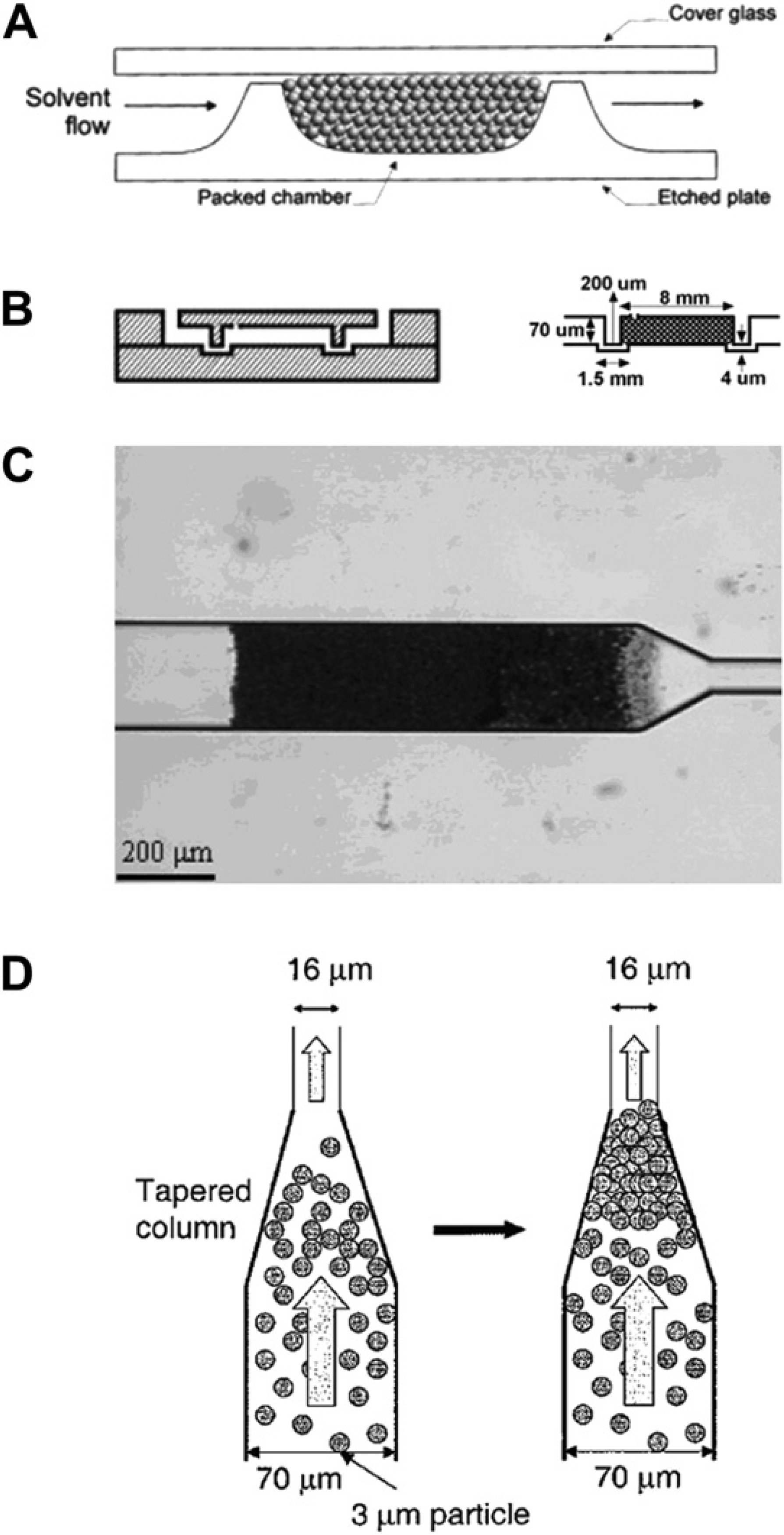
Retaining packed beads in microchannels. (A) Two-weir design, showing weir heights in relation to channel depth and particle size. Electroosmotic flow is driven by walls and by free silanol groups on particles. Solvent flow direction is indicated for a preconcentration step. (B) Two-side etching/alignment protocol. Two prefabricated plates were aligned and thermally bonded. On the right is a drawing of the cross section of a packed chip with its dimensions. (C) Photopolymerized frits retaining 3-μm-diameter beads. (D) The keystone effect. A suspension of particles is flowed toward the taper by vacuum. At the taper, the density of the particles increases, and these first particles act as“keystones,”blocking the others and allowing the packed segment to grow. Adapted and reproduced from Refs. 82–85, with permission from ACS and Wiley.
Packed-bead columns have disadvantages in terms of packing procedures and frit fabrication, which complicate microdevice preparation. On the other hand, monoliths are an attractive alternative to packed particles because of low back pressure and high surface area. 86 Thermally polymerized monolith materials have been successfully applied as SPE columns. 87 In 2001, Yu et al. 79 photopolymerized a monolith column in a microfluidic system and performed SPE. Enrichment of peptides and proteins up to 1000-fold was achieved on this column. More importantly, because of low back pressure, the linear flow rate in these monoliths could reach 10μL/min, which far exceeded flow in packed microchip columns.
Monolith columns have also been applied for DNA enrichment in complex mixtures like blood. However, nonspecific binding hindered elution of nucleic acids and decreased sample loading capacity because of competitive adsorption; the presence of proteins lowered the monolith extraction efficiency from ∼80% to < 40%. 88 Therefore, Wen et al. 89 developed a two-stage microchip SPE system. Before monolith column extraction, a C18 reversed-phase column was used to remove proteins in the sample. Although the procedure was more complex, whole-blood DNA extraction capabilities were significantly improved. For a 10-μL whole-blood sample, ∼ 70% of the protein was removed by the C18 column, affording more interaction between DNA and the monolithic material. This two-stage system enriched DNA ∼20-fold in the reversed-phase portion, and the overall DNA extraction efficiency was ∼70%.
In the previous applications described, microchip monolith SPE enriched analytes based on general interactions like hydrophobic absorption. To improve the selectivity, affinity elements can be immobilized on a monolith. Glycoproteins were retained on a monolith with immobilized agglutinin and then eluted in several fractions because of different affinities. 90 Yang et al. 91 prepared anti-FITC-modified sample pretreatment monoliths in microfluidic devices. FITC-labeled amino acids were enriched 20-fold and purified from a mixture containing a contaminant protein. However, the extraction and separation were performed on separate devices, which hindered automation. To circumvent this, Sun et al. 92 coupled anti-FITC affinity monoliths with electrophoretic analysis on a single device. Sample loading, rinsing, elution, and separation were all performed in an automated manner by controlling the potentials applied to various reservoirs. FITC-tagged species were selectively retained by the immunoaffinity column and separated from other contaminants. The retained proteins were then eluted from the monolith with 200 mM acetic acid.
In addition to monoliths, other affinity columns have also been integrated into a microfluidic format. For instance, microchannel surfaces were coated with silane and then protein A via physisorption. 93 Rabbit immunoglobulin G was concentrated and detected at 50-nM levels. However, this approach, as well as the other monolith work discussed previously, was only tested for capturing target analytes in buffer solutions instead of complex matrixes like tissue or blood. Recently, Yang et al. 94 developed an integrated microfluidic system to perform quantitative determination of alpha-fetoprotein (AFP) in human serum using both the method of standard addition and a calibration curve (Fig. 3). The microdevices were made of poly(methyl meth-acrylate) (PMMA), and a photo-defined polymer was formed on the microchannel surface, which allowed antibody immobilization. All assay steps, including affinity extraction, elution, separation, and quantification, were performed on-chip in an automated manner via changing the applied potentials in the reservoirs. AFP concentrations in human serum measured in these microdevices using both calibration curve and standard addition methods compared favorably with those determined using a commercial assay kit. Phillips and Wellner 95,96 have used immunoaffinity CE to measure biomarkers and neuropeptides in human biopsies. The analytes were captured by a replaceable immunoaffinity disk having attached antibodies. After removing nontarget materials, the captured analyte was labeled in situ, released, and then separated by microchip CE. The system was semiautomated, and the separation step was completed within 5 min.
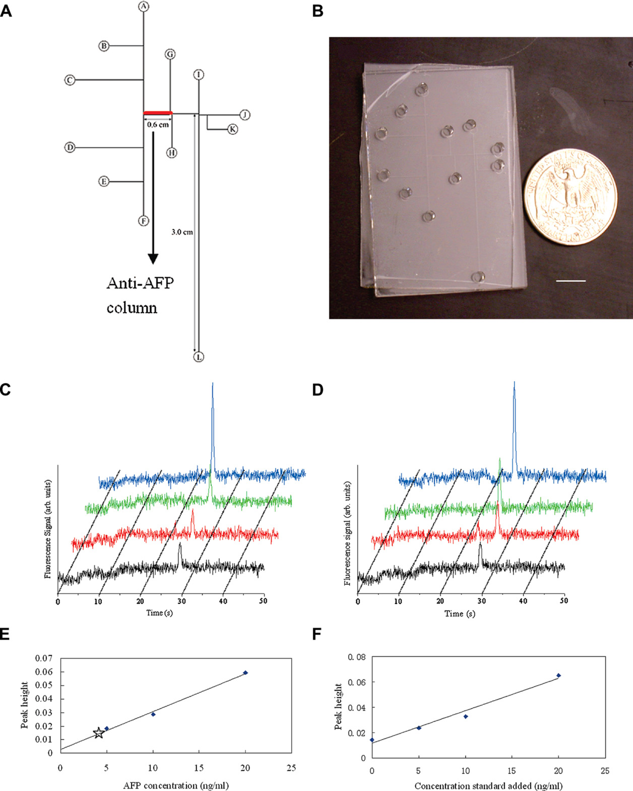
Integrated affinity column—microchip CE devices for biomarker quantitation. (A) Layout of an integrated AFP analysis microdevice. (B) Photograph of a microfluidic device with integrated anti-AFP affinity column. Scale bar is 1 cm. (C) Microchip CE of Alexa Fluor 488-labeled human serum and of AFP standard solutions after affinity column extraction. (D) Microchip CE of Alexa Fluor 488-labeled human serum after standard addition and affinity column extraction. (E) Calibration curve generated from peak heights in (C), with the unknown sample data point indicated with a star. (F) Standard addition plot of concentration of standard added versus peak height generated from peak heights in (D). Adapted and reproduced from Ref. 94, with permission from ACS.
Nonelectrically driven immunoassays can also be performed in microchip devices. For instance, Kong et al. 97 formed elastomeric microvalves in three-layer microchips to control flow, although the valves were actuated by a vacuum pump and a compressor. Using this system, clenbuterol was determined in pig urine samples in 30 min. Fan et al. 98 designed a PDMS-on-glass microsystem to perform protein assays on blood samples. Plasma was separated from whole blood on chip, and selected proteins were detected by antigen—antibody interaction.
The variety of column materials used thus far (commercial silica particles, monoliths, etc.) indicates that consensus is still lacking as to the optimal column properties. Future efforts should focus on determining which type of column works best for a given analysis. In addition, further work is needed to streamline and simplify column fabrication.
Membrane Filtration
Another common method for sample preconcentration and cleanup is membrane filtration, which uses the size difference between analytes and buffer ions. Larger molecules cannot pass through a porous layer in a semipermeable hollow fiber, 99 membrane, 100 or joint, 101 whereas smaller species are allowed to transit. In one design, a porous membrane was sandwiched between two PDMS pieces to create a three-dimensional microfluidic channel structure. 102 This system achieved 300-fold concentration of fluorescein in ∼40 min. The fluorescein was concentrated outside a 10-nm pore membrane (with openings larger than the molecular size of fluorescein), because the negatively charged diffuse layer on the interior of the membrane repelled anions. Song et al. 103 used a laser to pattern a nanoporous membrane at the junction of a cross-channel. This device could concentrate proteins more than 100-fold in 2 min, and the degree of concentration was limited only by analyte solubility. Similarly, an anionic polyacrylamide gel preconcentrator was laser photopolymerized in one arm of a cross-channel in a PMMA microdevice. 104 The negatively charged sulfonate groups in the gel repelled negatively charged proteins, enabling concentration of proteins up to 100,000-fold. Foote et al. 100 used a silicate membrane deposited between two adjacent microchannels, and a ∼600-fold signal increase for proteins was achieved. Kim and Han 105 developed a simple protocol to fabricate a nanoporous membrane in microdevices. They used razor blades to form a gap in microchannels in a PDMS substrate; Nafion 117 was then filled into the gap and a portion of the microchannels via capillary forces. In this protocol, preconcentration was achieved in large channels with dimensions up to 0.1 × 1 mm.
Semipermeable membranes can also be integrated with other microchip functionalities. Herr et al. 106 fabricated a size exclusion membrane at the injection junction of a microdevice, allowing antibody enrichment at the membrane surface. Sample loaded on the membrane was captured through antigen—antibody interaction, and enriched species were eluted into a separation channel for electrophoretic immunoassay. This system measured a biomarker for periodontal disease in saliva in < 10 min with comparable results to conventional methods. A similar design has been developed into a portable diagnostic format for rapid detection of biological toxins. 107 A membrane can also be used for SPE. Lion et al. 108 integrated a poly(vinylidene difluoride) membrane to desalt and concentrate samples before analyzing with mass spectrometry. Kim and Gale 109 sandwiched an aluminum oxide membrane between PDMS pieces; when a blood sample passed through the membrane, DNA was selectively enriched and then eluted with buffer. The extraction time was < 10 min, whereas the recovery was ∼40 ng of DNA per microliter of blood. A membrane has also been applied to enrich nonvolatile analytes by evaporation to reduce the amount of liquid phase. 110 The membrane was located at the interface between a gas and a liquid channel; sample was introduced into the liquid channel, and water evaporated into the gas channel through which nitrogen was flowing.
Presently, membranes are formed through sandwiching between channels or photopolymerization. Although these methods work acceptably for prototyping efforts, more straightforward fabrication techniques will be needed in the future. Moreover, the relatively slow rate of enrichment in membrane-based systems is an issue that could be addressed with high-speed membrane-based filtration devices.
PCR Amplification for DNA Analysis
PCR is an exponential amplification technique for DNA diagnostics. The method relies on thermally cycling samples in different temperature zones as follows: denaturation to single-stranded DNA, annealing primers to the single-stranded DNA template, and polymerase extension of the annealed duplex DNA. Miniaturization of PCR allows rapid thermal cycling, small sample quantities, and potential to integrate with other microfluidic methods. Since the first report of integrated PCR—CE microdevices, 111 considerable progress has been made in the coupling of PCR with other technologies (CE, immunoassay, cell isolation, DNA arrays, etc.) on microdevices. Because Chen et al. 112 reviewed integrated PCR microfluidic technologies in 2007, we focus here on more recent breakthroughs in the field.
Liu et al. 113 developed a portable microsystem for forensic genetic analysis. All the electronics for temperature control, microfluidic manipulation, and CE separation, as well as optics for four-color LIF detection, were integrated in a 12 × 10 × 4-in. 3 box. Oral swabs and human bone extracts were successfully analyzed by this system in less than 1.5 h. To improve on the efficiency of cross-injectors, an inline injection system 114 with DNA-based affinity capture was developed. Immobilized oligonucleotides in a polyacrylamide gel provided more efficient injection of DNA fragments while cleaning up sequencing samples. Subsequently, a photo-defined, cross-linked polyacrylamide gel affinity matrix was integrated with PCR—CE microdevices. 115 This affinity system increased the injection efficiency to nearly 100% and minimized band broadening. The devices were evaluated in detecting diluted
Continuous-flow PCR offers another format for integrating PCR into microdevices. In this approach, instead of heating and cooling a sample in a fixed location, three regions on a device are maintained at constant temperature, and the sample is passed repeatedly through these zones to thermally cycle. Recently, Sun et al. 116,117 developed systems in which PCR solution was driven magnetically around a loop in either one channel or multiple channels. As shown in Figure 4A, the system had three temperature zones, a magnet, and a ferrofluid (a stable suspension of magnetic particles in oil). With the rotation of the magnet, the ferrofluid plug moved accordingly and cycled the PCR mixture around the circular channel. This system was applied in amplifying genetically modified soy and maize samples in less than 13 min.
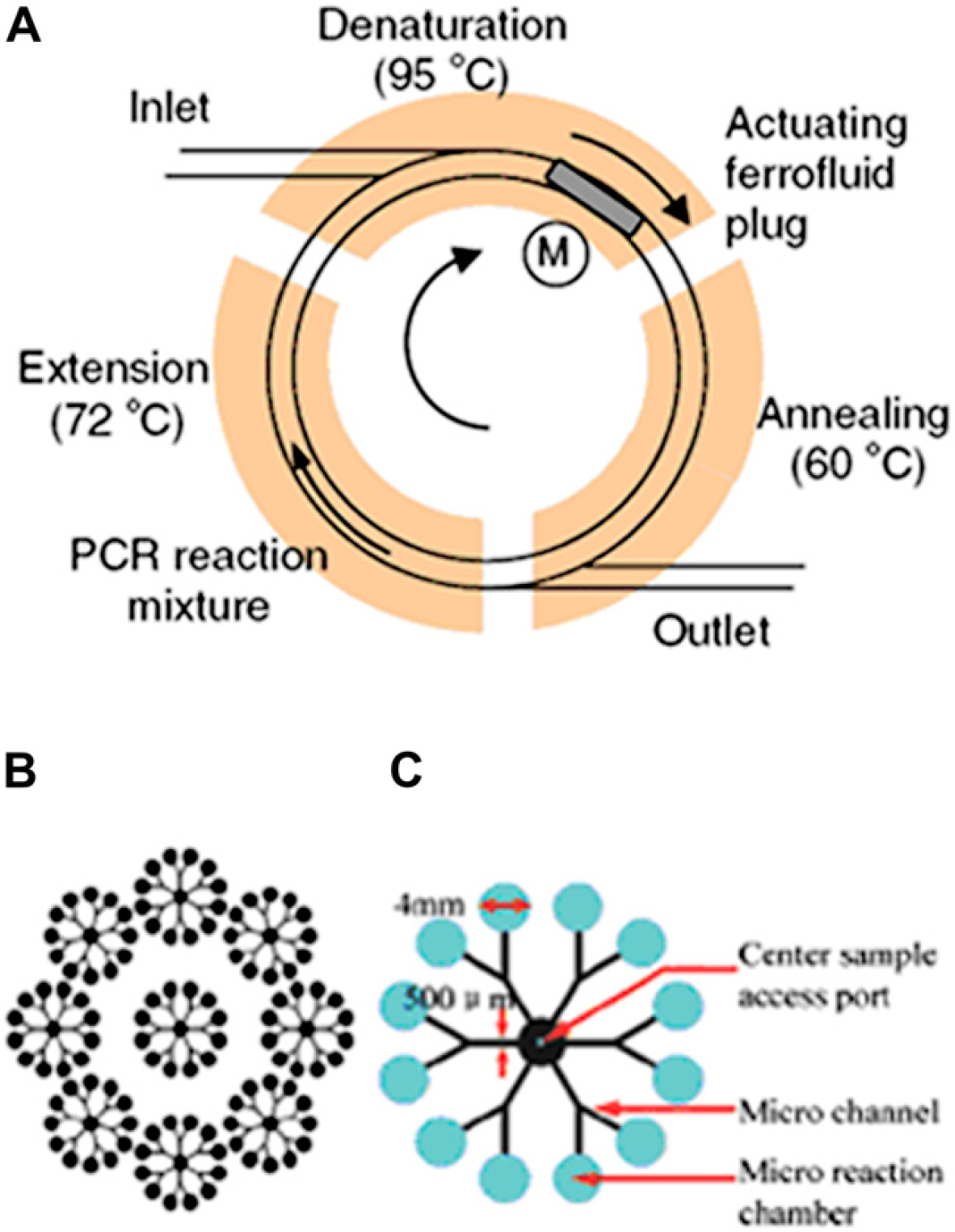
Integrated PCR microdevices. (A) Continuous-flow PCR driven by the magnetic force. PCR reaction mixture, pushed by a ferrofluid plug, flows continuously through three temperature zones in the circular channel. (B) PCR array device layout for DNA methylation analysis. Nine functional units are arranged in a circular pattern. A total of 108 reactions can be done with nine sample injections, which significantly improves the throughput. (C) Functional unit layout. The sample inlet has a 0.64 mm diameter, and reaction chambers at the periphery have a 4 mm diameter. Primers specific for tumor suppressor promoters are deposited onto the bottom surface of designated reaction chambers by pipetting. Adapted and reproduced from Refs. 116 and 118, with permission from Springer and RSC.
Methylation-specific PCR is used to analyze DNA methylation, which is associated with tumorigenesis. Zhang et al. 118 developed a droplet-in-oil microfluidic system for high-throughput DNA methylation detection. The design layout, which allowed 108 reactions to be performed in parallel, is shown in Figure 4B,C. The droplet-in-oil protocol reduced contamination and prevented evaporation during thermal cycling.
Integrated PCR methods have become rather advanced such that many important areas for future work will be in the application of these high-performance systems to real-world problems. Large-scale implementation of integrated microchip PCR is envisioned in fields such as food safety testing and forensics.
Summary
The advancement of microfluidic technologies has provided faster and smaller analysis systems. However, the detection limit and peak capacity of many microdevices are not ideal for trace analyses in complex mixtures. Integrating multiple sample preparation functions into microfluidic formats can improve throughput, simplify pretreatment, and, most importantly, automate processes.
Multidimensional microdevices can significantly increase speed in complex sample analysis; however, the inability to analyze highly complex mixtures remains a limitation for these systems. Array platforms can analyze either one sample in parallel or many samples simultaneously; to date, 384 parallel lanes have been integrated into a microdevice. Online labeling can eliminate sample preparation steps and increase analysis speed while automating processes. Multiple dye attachment in precolumn labeling can result in band broadening; furthermore, choosing an appropriate dye is critical for postcolumn labeling. To preconcentrate sample or remove impurities before analysis, SPE and membrane filtration have been integrated into microdevices. Samples can be concentrated by two to four orders of magnitude under optimized conditions. For on-chip SPE, packed beads and monolith columns are widely used as stationary phases. Packed particles in microchannels require a suitable retaining structure. Monoliths are attractive because of low back pressure and high surface area. Integrated affinity extraction can effectively capture target components from a complex matrix and therefore is desirable for biological sample analysis. Semipermeable membranes can enrich samples up to 100,000-fold, although further work is needed in developing straightforward fabrication methods. PCR can be integrated into portable microsystems for various genetic analyses, and progress continues in this area.
Multifunctional microdevices have allowed researchers to analyze biological samples in an automated manner. Importantly, integrated microchips have provided improvements to sample throughput, peak capacity, and LOD. With continued development, integrated microfluidic devices will be more robust and fully automated for high-throughput complex sample analysis in the near future.