
Abstract
Hydrophobic microfluidics is a method for controlling fluid flow in microfluidic systems using short restrictions in channel diameter that act as passive valves. Systems designed using hydrophobic microfluidics have the advantage of easily interfacing with external hardware and integrating with external analysis equipment. This allows it to take advantage of both the micro and macro realms, whichever is most suited for the application, as well as allowing for an inexpensive integration of microfluidics into a company's sample analysis protocols. This method of fluid control is excellent for highly parallel sample analysis, such as DNA processing.
INTRODUCTION
It has been known for quite some time that fluid-surface interactions become very significant in micro-scale devices 1. The capillary effect is a common example of such an interaction. It is usually depicted by water being drawn into a hydrophilic (e.g. glass) capillary tube, but the reverse is also true, wherein water resists movement into a hydrophobic (e.g. Teflon”) tube. The amount of capillary force generated in a tube is proportional to its radius. In the case of hydrophobic materials, a narrower tube requires a greater force to push water into it. Hydrophobic microfluidics exploits this natural phenomenon to passively control the flow of fluid within a microfluidic circuit. If a flow channel is coated with or is made of a hydrophobic material, water flowing in the channel will require greater pressure to push past a restriction than if the restriction were not present. Once past the restriction, the pressure drop required to maintain flow across it is very little, if the restriction is very short, and its net effect on fluid flow is negligible. Figure 1 illustrates the positive and negative capillary effects, depending on whether the material is hydrophilic or hydrophobic, and shows an example of a short restriction in a flow channel.
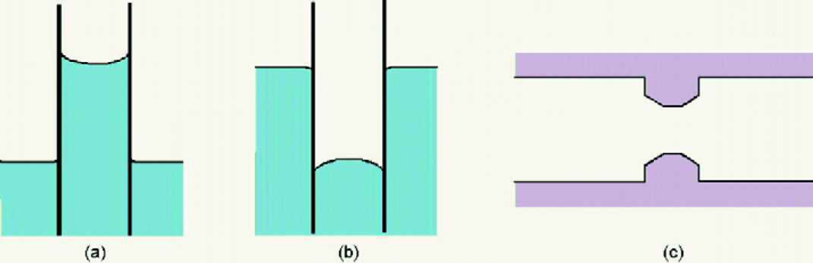
Positive (a) and negative (b) capillarity, and (c) a restriction in a flow channel.
MICROFLUIDIC COMPONENTS BASED ON PASSIVE VALVES
Mixer
Figure 2 illustrates the passive valve mixing concept. Instead of two inlets that contain two different fluids, only one inlet is necessary for both fluids, which flow in series (one behind the other). The use of one inlet rather than two is useful in highly multiplexed circuits where there is often not enough space for multiple inlets, and where it is not cost effective to develop a three-dimensional system. As indicated in the figure, the two fluids initially flow down channel 1 until they encounter a branched channel, channel 2, and a restriction at point a in channel 1. This restriction diverts the fluid flow into channel 2. Channel 2 is designed to rejoin channel 1 at b, where a second restriction is located. The restriction at b is narrower than the first restriction, which forces the second fluid through the restriction at a and causes it to resume flowing down channel 1. The restriction at b is designed such that as the fluid flows in channel 1 past point b the two fluids touch and the meniscus that was in channel 2 goes away. This causes the restriction at b to effectively disappear. As fluid continues to flow it will move through both channels 1 and 2 at a rate dependent on the channels' respective impedances. At point b the two fluids join along side each other and the surface area available for diffusional mixing increases considerably.

Mixer using passive valves.
DIVISION AND MULTIPLE WELL FILLING
It may be beneficial in some microfluidic applications to split a single sample up into multiple samples for separate processing. Figure 3 shows a method of sample division using passive valves. Restrictions are placed at strategic locations within the dividing channels to cause fluid to catch-up to itself in each branch, before continuing further. This allows a fairly even flow down each branch, and causes a sample to be evenly distributed across all fluid paths. Restrictions placed at the outlets of wells regulates uniform well-filling before the fluid continues further down the circuit. If the combined volume of the fluid channels and wells is known, then a pump that supplies fluid to the circuit can be programmed to stop, once a specific volume has been delivered. This would allow the pump to fill all wells and then stop, so some process can take place within the wells. Once the process is complete, the pumping can start up again to push the samples further down the circuit path.

Sample division and multiple well filling using passive valves.
CONSOLIDATION
Consolidating multiple samples into a single sample is another useful capability. This may be accomplished in several ways using passive valves, however, only one will be illustrated here. This method takes advantage of both the passive valve technique, and the pressure drop required to push a highly viscous solution through a long narrow channel, rather than a short restriction. Figure 4 illustrates this method. All four wells are filled with samples that are maintained in the wells because of the narrow outlet channels. A second, more viscous solution is present in the system upstream to the first. As the pump pushes, the viscous solution will push one of the samples into the narrow channel that leads to the consolidation well. When the viscous solution reaches the narrow channel it will be harder to push it through the channel than it would be to push the neighboring well into its outlet channel. The second well will, preferentially, be pushed into the consolidation well. This process continues until all four wells are emptied into the consolidation well.

Consolidation using a second viscous solution.
AIR ESCAPE/INJECTION DUCTS
A common application of hydrophobic microfluidics is to allow air to escape a fluid system. Air escapes easily out of small channels that would require possibly tens or hundreds of psi pumping pressure to push water through 2,3 . In addition, air can be injected into a system to help meter a fluid volume 4 , or, perhaps, to re-set a passive valve so multiple-batch processing can take place.
ADVANTAGES AND DISADVANTAGES OF HYDROPHOBIC MICROFLUIDICS
There are many advantages to hydrophobic microfluidics. The two most important will be discussed here. First, it is passive and requires no voltage control, other than the power needed to run a pump. This would be important in low power systems, such as portable systems, or low voltage systems, such as those where sensitive electronic circuitry is integrated with the fluidics. Second, no extensive sealing method is needed to keep the fluid within the channels. A hydrophobic system could be completely open to allow interfacing with external hardware, and then simply covered with a hydrophobic sheet and pressurized a little above the maximum pressure the fluid is expected to reach during the processing cycle. After processing, the sheet could be removed so the plate could again interface with external systems. This ability to interface with external hardware facilitates a considerable advantage of utilizing the benefits of microfluidics as well as the superior abilities of some macro external systems, such as capillary electrophoresis machines.
The most significant disadvantage associated with hydrophobic microfluidics is that the effectiveness of passive fluid control is reduced when a large concentration of surfactant or some organic solvents (such as ethanol) are present in the aqueous solution. The exact concentration of surfactant or solvent that can be tolerated by a restriction varies, but passive valves have been seen to function properly at levels of around 0.05% (Tween 80). Higher concentrations may still be amenable for use, but the reduction in channel diameter may need to be greater for the passive valves to function properly.
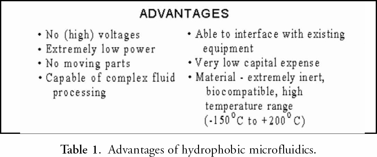
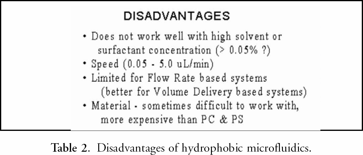
Additional advantages and disadvantages exist, but they are mostly application specific. These are shown in
Advantages of hydrophobic microfluidics.
Disadvantages of hydrophobic microfluidics.
SYSTEM APPLICATIONS - DNA SEQUENCING AND GENOTYPING
The advantages of hydrophobic microfluidics allow it to be useful in a wide range of applications. These include industrial process monitoring, micro reaction systems, synthetic chemistry, drug discovery, discrete fluidic components, in-vitro diagnostics, and sample preparation for bio/chemical analysis. Examples of how this passive fluid control may be applied in genetic analysis will be explained here.
Figure 5a, b, and c show possible fluid circuits that could be used for genotyping, dye primer sequencing and dye terminator sequencing. As can be seen, these circuits use the type of fluid control elements that have already been discussed (i.e. division, consolidation, etc.), dye primer sequencing being the most complicated. In the dye primer sequencing case, Figure 6 shows an example of the steps a laboratory technician may utilize to analyze 96 samples using standard microtiter plates, a robotic pipetting workstation, and a thermal cycler to perform PCR. Figure 7 shows how this procedure could be simplified using a BioMicro microplate, which has 96 fluid processing circuits spaced in the same format as a 96-well microtiter plate.


Macro DNA protocol.

Micro DNA protocol.
BioMicro Systems has worked closely with Myriad Genetics, Inc. to develop the hardware and chemistries that allow this process to be realized. The microplate is designed so that it can interface with standard pipetting systems, such as for the loading of reagents and samples. It is also designed to fit in a thermal cycler that has been slightly modified so as to allow the microplate to interface with external pumps. A buffer solution is pumped into the microplate that re-hydrates the samples and reagents and pushes them through the fluid circuit, where they stop at various places to allow for processing to take place, such as PCR. Once the processing is complete, the microplate is designed to be removed from the thermal cycler and the samples loaded, either automatically or manually, onto a capillary or slab gel electrophoresis machine.
This system has all of the advantages associated with microfluidics, such as a reduction of costs due to smaller reagent volumes, integrated fluid handling to increase quality control and reduce operator intervention, and greater automation. It also has the ability to interface with external systems for reagent and sample loading, and to utilize the (currently) superior detection capabilities of macro-electrophoresis machines. A high-throughput sequencing company could convert to this method of DNA processing with extremely little trouble or overhead costs. This is due to the fact that the microplate is designed to interface with existing equipment, and the sequencing company probably already has the most expensive component of this system, an electrophoresis machine. The costs of converting to and utilizing this technique would be recovered within weeks, mostly due to the savings associated with less operator intervention, greater quality control, and less reagent usage.
The fluid components that have been discussed here have been successfully developed and tested at BioMicro Systems. The 96-circuit microplate, and other system components, are still under development. Videos of functional fluidic components are available for viewing at www.biomicro.com, under the slideshow link. Figure VIII shows results of biocompatibility testing by performing PCR in microwells made in hydrophobic fluorocarbons. Figure IX shows an example of a fluid circuit made in plastic.
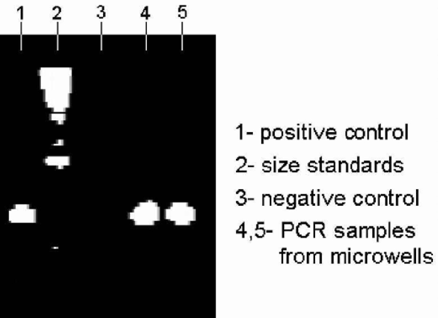
Amplification of 800bp fragment of BRCA 1 gene in microwell.

An example of a fluid circuit fabricated in plastic.
CONCLUSIONS
Hydrophobic microfluidics represents an alternative to pneumatic and electric field based fluid control techniques. It is completely passive, inexpensive, and allows for active device integration when needed. Although the examples that have been given rely on external detection and analysis, they could also be integrated within the fluidic system, if needed.
The integration of macro-wells with micro channels, as well as the less rigorous sealing requirements associated with hydrophobic materials, allows such systems to interface with macro, external devices. This allows the advantages of microfluidics, such as lower operating costs and greater quality control, to be integrated with the advantages of macro systems, such as (currently) superior detection and analysis. Since the microplate is designed to interface with common microtiter plate based systems, the cost associated with integrating microfluidics into a company's protocols should be kept fairly low.