
Abstract
Sensor-based coverage problems have many applications such as patrolling, search-rescue, and surveillance. Using multi-robot team increases efficiency by reducing completion time of a sensor-based coverage task. Robustness to robot failures is another advantage of using multiple robots for coverage. Although there are many works to increase the efficiency of coverage methods, there are few works related to robot failures in the literature. In this paper, fault-tolerant control architecture is proposed for sensor-based coverage. Robot failures are detected using the heartbeat strategy. To show the effectiveness of the proposed approach, experiments are conducted using P3-DX mobile robots both in laboratory and simulation environment.
Introduction
Multi-robot sensor-based coverage path planning problem requires that every point in a given area should be covered by at least one member of the robot team using its sensors (Acar et al., 2006). This problem appears in applications such as landmine detection, patrolling, search-rescue, and surveillance (Trevai et al., 2007).
In the literature, there are several studies on multi-robot coverage problem. In an early work (Kurabayashi et al., 1996), the configuration space and Voronoi diagram are used to compute paths in the whole area. Firstly, a tour is generated for travelling all the paths, and then appropriate parts of the tour are assigned to each robot according to the cost evaluation. The cost is evaluated in terms of the traveled distance by each robot. The approach in (Latimer et al., 2002) presents an adaptation of the single-robot cellular decomposition approach to multi-robot teams. A robot team moves in a formation to cover cells. If obstacles divide the environment into sub-regions, team splits up into smaller teams to continue coverage task. In (Kong et al., 2006), authors build their approach on a single-robot coverage algorithm, boustrophedon decomposition. The robots are initially distributed through the free space. Then, each robot is allocated a virtually bounded area to cover. The area is decomposed into cells with fixed width. In (Mei et al., 2006), mobile robot deployment problem is considered for a specific type of coverage problem. The deployment problem is described as determining the number of groups to be unloaded by a carrier, the number of robots in each group, and the initial locations of those robots. Both timing and energy constraints of robots are considered. Power consumption of mobile robots is modeled and the energy cost of possible scanning lines for coverage are calculated. Then, the deployment problem for the members of the team is solved for each robot considering their energy capacities. In (Parlaktuna et al., 2009), an approach based on capacitated arc routing problem (CARP) is proposed and applied to multi-robot sensor-based coverage planning for narrow interior environments. The proposed algorithm is developed by modifying Ulusoy's partitioning algorithm. Basically, the proposed algorithm uses CPP/RPP (Chinese Postman Problem/Rural Postman Problem) solving techniques in the initial phase; then it partitions the tour among the robots considering their energy capacities.
These works intend to increase the efficiency of multi-robot coverage problem; but, they do not consider robot failures. If one of the robots fails, the regions assigned to this robot must be covered by other robots to guarantee complete coverage of the given area. Therefore, multi-robot control architectures must be designed to handle such failures. If the robot is not able to inform the team about its failure, the team must detect the failure and distribute the uncompleted tasks of the failed robot among the remaining robots. The work by (Hazon, N. & Kaminka, G.A., 2008) is one of the few works that considers robot failures for multi-robot coverage. The authors analytically showed that their proposed algorithms are robust in that, as long as a single robot is able to move, the coverage will be completed. This work is proposed in algorithmic level; therefore, robot failure detection and software architectures are not given.
In this study, fault-tolerant control architecture is proposed for sensor-based coverage. The paper is organized as follows: In Section 2, fault-tolerant control architecture is explained. Applications of the proposed approach are given in Section 3. Conclusions and discussions are given in Section 4.
Fault-Tolerant Control Architecture
The proposed fault-tolerant control architecture consists of software agents performing specific functions like communication with other robots, perception, action, fault detection, planning, human interaction, etc. Fig. 1 shows overall block diagram of the architecture for n robots. Each dashed-square shows a robot in the team, and each block inside a robot represents a software agent. In the proposed architecture, each robot has four functional software agents: user interface agent (UIA), planner agent (PA), action agent (AA), and communication agent (CA). The functional details of the agents are defined as follows:
The main task of this agent is to provide interaction between the robot and users. It provides a user-friendly environment to define tasks and provides information about the internal state of the robot via terminal or graphical interface. This agent is responsible for generating plans which may include motion planning, path planning, task planning, etc. It contains planning mechanisms which use the planning algorithms for different task domains. It is able to generate plans for one or more robots. This agent is responsible for tasks related to hardware of robots (actuators and sensors). It performs behavior-based motions according to motion plans provided by the PA. The task-oriented behaviors are implemented in conjunction with the survival behaviors, such as obstacle avoidance, by coordination of subsumption approach (Murphy, R.R., 2000). This agent is also responsible for robot's high-level perception and localization. This agent is responsible for interaction with the other robots. The interaction takes place over the infrastructure which is realized using TCP/IP. The robots communicate each other explicitly via the CA. This agent may also be responsible for some other tasks like fault detection as in our study.
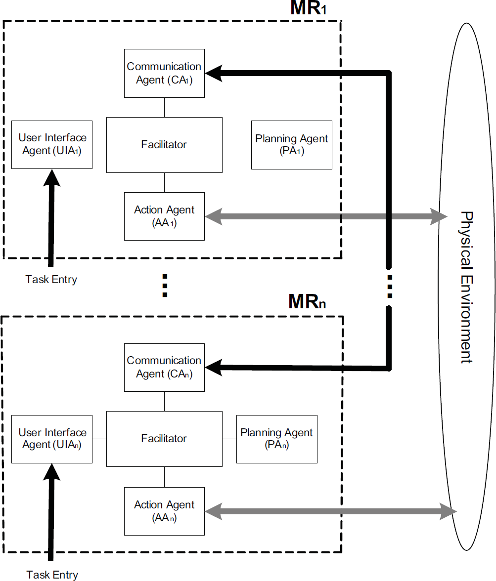
Overall block diagram of the architecture
All of the agents are in the separate computational processes which perform tasks according to their designed purposes. The messaging between the agents is managed by another software agent, facilitator. Open Agent Architecture (OAA) (Martin et al., 1999) is used as an infrastructure framework to provide content-based message transfer between the agents.
Planning and fault detection play important roles in the proposed architecture. In the following sub-sections, planning for coverage problem and the fault detection mechanism are explained in more details.
The planning process is initiated by one of the three following events: task entries by the user, blocking obstacles detected by any robot and robot failures (Fig. 2). In the first type of event, the user submits a coverage task for a specific region via terminal or graphical interface provided by the UIA. Then the user-defined task is formatted using a messaging language and sent to the PA to generate partial plans. The second type of event occurs when the robot faces with unforeseen obstacles located on its path. The obstacles are detected by the AA which manages perceptual and motional tasks of the robot. If the AA concludes that the obstacle blocks its planned path, it informs the PA to initiate the planning process. The last type of event, robot failures, is explained in detail at the succeeding section.

Sequence diagram of the events to initiate planning
After one of the events that are explained above occurs, the planning process is initiated. It consists of three phases as seen in Fig. 3. In the first phase, PA
i
requests the state and location of each robot (MR
j
where, j =1,…,n, j ≠ i) via the CAi. The second phase is the planning according to the obtained information. The planning phase constructs partial path plans which will be allocated to the robots. The partial plans are generated by using the RPP and the CARP-based solution approaches (Yazici et al., 2009). The environment is modeled by a Generalized Voronoi Diagram (GVD) based network G=(V,E). The edges that must be visited are called required edges. The planning approach mainly has the following steps:
Determine the required edges, current position and remaining energy capacity of each robot from the obtained information from the robots. Construct an Euler tour that covers all the required edges using the RPP approach. Partition the Euler tour using Dynamic Ulusoy Algorithm (Yazici, et.al., 2009).
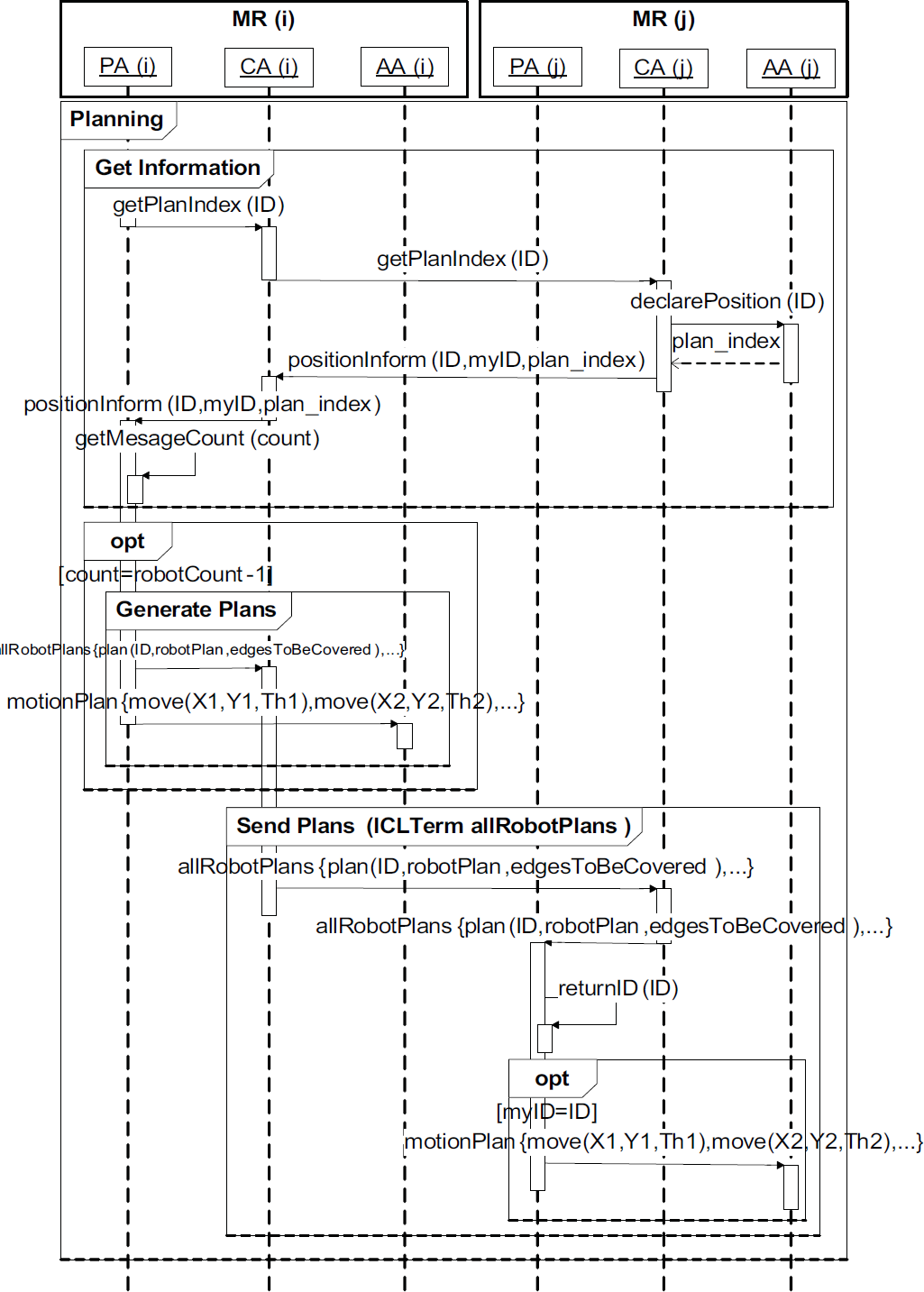
Sequence diagram for the planning
In the last phase, the partial plans are dispatched to each robot via the CA i while its own plan is sent to the AA i .
Robot failures are classified into three fundamental categories: (i) Communication failures, (ii) partial robot malfunctions, and (iii) robot death (Dias et al., 2004). Communication failures take place in distinct domains and ranges from occasional loss of messages to loss of all communication. If a partial malfunction occurs in one of the abilities of the robot, the robot loses its ability to effectively use some of its resources but retains the ability to use other resources. If this malfunction is related to the assigned task, this robot may be considered dead. In the final category, the robot may die as a result of battery depletion, a hardware breakdown, or the crash of the software operating system. In all of these cases, robot failure must be detected by a detection mechanism.
Several methods were proposed to deal with the fault detection problem. One of the classical techniques of failure detection is socially attentive monitoring which is based upon detecting the failed robot by its teammates (Parker, L., 1998). Other approaches are pinging and heartbeat strategies (Bertier et al., 2002). In the pinging strategy, an agent periodically sends requests to the other agents and waits their replies (Christensen, A.L., 2009). However, in the heartbeat strategy the agent periodically sends heartbeat messages known as “I'm alive” to other agents in order to inform them about its aliveness. At first, the heartbeat strategy is generally applied on processes in multi-agent systems (Faci, N., 2006; Pasin, M, 2008) and then it is applied to mapping and target acquisition tasks in multi-robot systems (Barnhard, D., 2005; Dobre, C M., 2009).
In this study, the heartbeat strategy is used to detect the failed robots. The heartbeat strategy system for an n-robot team (Π{MR1, MR2,…, MR n }) is implemented by sending and receiving messages via the CA. Message traffic between a pair of robots (MR i and MR j ) is shown in Fig. 4. In this figure, the heartbeat period of MR i , Δ i , is the time between two “I'm alive” messages. tr−1 is the time at which the last heartbeat message from MR i is received by MR j . The control time, t control-j , is used to periodically check whether the heartbeat signal from MR i is received or not by MR j . The delay time, Δ td-i , is the difference between the control time and the time of the last received heartbeat message (Δ td-i = t control-j - t r-i where t control-j ⩾ t r-i ). The timeout, Δ to-i , is a predefined duration which should be greater than Δ i . MR j concludes that MR i has a failure when Δ o-i < Δ d-i .

Heartbeat strategy for mobile robots
If Δt o-i − Δ i is short, the failures are detected in a short time, but likelihood of false positive failures increases due to communication delays. If the maximum communication delay, Δtcd_max, in the network is known, Δt o-i should be greater than Δ i + Δtcd_max.
This heartbeat strategy is implemented using the control architecture as explained in the following subsection. Since each robot is able to detect the failure of any other robot in the team, this is a distributed fault detection strategy.
Fault-tolerant coverage planning is achieved by implementing the heartbeat strategy in agent-based robot control architecture. The fault detection mechanism explained in the previous section uses a status table stored on each robot. The structure of the table is given in Table 1. This table holds information about other robots in the team.
Status table for MR
i
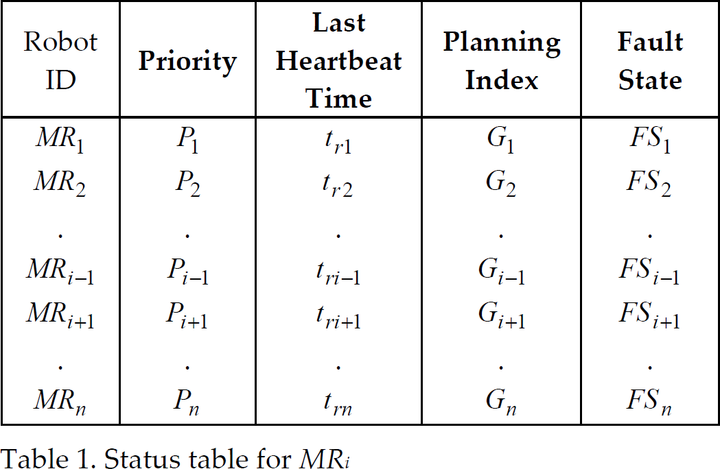
Status table for MR i
In this table, the first and the second columns hold unique numbers and planning priorities of other robots, respectively. The third column represents the last received hearbeat message's time from MR j (j = 1,…, n, j≠i). The fourth column holds the planning indexes of other robots. The planning index is used to determine approximate physical location of the robot when the last heartbeat signal is received. The last column holds the fault state of the robot i, FS i , as alive or dead. This status table is handled and updated by the CA of each robot.
The sequence diagram of the fault detection process performed by the CA i is given in Fig. 5. In this sequence diagram, the CA i realizes three tasks as explained below.

Sequence diagram for the fault detection
In this phase, each robot prepares a status message and sends it periodically to all other robots at the end of the predetermined heartbeat time interval. This message consists of robot's id and its plan index value (“status(robotID, plan_index)”). This shows that the robot is alive on that instant.
Message receiving
When a robot receives status message from any robot, it updates the corresponding row of the table (Table 1). The last heartbeat time entry of the table is updated according to the local time of the receiving robot.
Status Check
All robots check their tables periodically at the end of Δ control-j duration. On control time, t control-j , the robot compares its local time with the last heartbeat time of all other robots. If the time interval between the last heartbeat time and the control time is greater than Δ to-i , then the robot i is considered to be dead.
If robot failures are detected, then the ID of the failed robots are sent to all other robots with a message of robotFailure(‘failedID1, failedID2, …’). Then, the CA of the robot with the highest priority informs its PA about the failure with a message of planFaultDetection(“failedID1, failedID2, …”, “plan_index1, plan_index2, …”). Finally, the PA gathers planning indexes of alive robots to initiate planning as in Fig. 3.
Application
The proposed fault-tolerant system is coded in C++ and tested using P3-DX robots both in laboratory and MobileSim simulation environments.
Application in Laboratory Environment
A platform at ESOGU Artificial Intelligence & Robotic Laboratory (AIRLAB, 2009) is used as the test bed (Fig. 6). In the applications, P3-DX robots are used. The P3-DX robot has an onboard P3-800 computer with Linux OS. The sensors on the robot are: the SICK LMS laser range finder, sonar sensors, camera, and compass. A wireless network is set for communication among robots and computers. Mainly the SICK LMS laser range sensor is used for the coverage task. This sensor has normally a range of 50 meters, but for experimental purposes the range is restricted to 3 meters with software. A topological map of the platform and GVD-based network considering 3 meters sensing range are given in Fig. 7. Complete coverage of the given area is achieved by following all the edges in this figure. In applications, localization is realized by using the ARNL software module (ARNL, 2007).

A photograph of the test environment

Topological map and GVD-based network of the test environment
In the first experiment, two P3-DX mobile robots (MR
1
and MR
2
), initially at node 1, are required to cover the given environment. After the coverage task was entered by the user via the UIA
1
, the PA
1
generated the paths for both robots. The tours are as follows; the tour for MR
1
: (

Robot tours during the coverage task
Another experiment is conducted to test the proposed fault detection mechanism. Robots start this experiment by using the same plan of the previous experiment. Up to 120 seconds, the experiment continued as in the previous experiment. At t=120sec., MR 2 is manually turned off. The fault detection mechanism and replanning results are explained in the following paragraphs.
The parameters of the fault detection mechanism are: Δ1=Δ2=10sec., Δcontrol−1 = Δcontrol−2=15sec., and Δto−1=Δto−2 = 20sec. Each robot logs its received and sent messages during the experiment for a detailed fault detection analysis.
Fig. 9 shows the heartbeat messages of MR 1 received by MR 2 . As shown in this figure, MR 2 regularly receives the heartbeat messages of MR 1 up to 120 seconds, and controls these messages from MR 1 at the end of each control period of MR 2 .

Heartbeat timing diagram of MR 1 received by MR 2
In Fig. 10, the heartbeat signals of MR
2
received by MR
1
are given. Up to 120 seconds, the heartbeat signals are received normally. The last heartbeat message from MR
2
has been received at t
r-2
=113sec. The next control time is t=120sec. At t=120sec., the delay time for the heartbeat signal of MR
2
, Δ
td-2
, is 7 seconds

Heartbeat timing diagram of MR 2 received by MR 1
After MR
1
detects the failure, it checks its priority table and notices that it has the highest priority for the replanning. Then, MR
1
generates a new plan to cover the remaining unvisited edges as follows: (

Complete tour of the robots
The response of the proposed fault detection mechanism is tested in MobileSim simulation environment. The same fault detection parameters of the previous experiments are used. The simulation is started with five robots, and one robot is killed after every 50 seconds. Fig. 12 shows the status of robot aliveness versus time graph. The thick lines show the duration at which the robot remains alive. Thin lines show the time period between the robot failure and the detection of this failure by the proposed fault detection mechanism. Dashed lines indicate the remaining time period.

The status of robot aliveness versus time graph
According to the thin lines, the failures of MR 1 , MR 2 , MR 3 , and MR 4 are detected 25, 20, 15, and 25 seconds later after their failures, respectively.
Moreover, the maximum communications delay time (Δtcd_max) is recorded as 5 seconds. Therefore, a timeout value of 20 seconds is acceptable for five robots considering the maximum communication delay time. A more detailed analysis related to communication delay vs number of robots is given in the following section.
The communication delay is analyzed up to 25 robots using the proposed control architecture. The columns of Table 2 show the average, the minimum, and the maximum delay for each experimental setting. Heartbeat signals are sent every 10 seconds, the control time is 15 seconds and the fault detection time is set to 200 seconds. As seen in Table 2, the maximum communication delay increases polynomially as the number of robots increases.
Communication delays

Communication delays
To avoid false-positive fault detections, the minimum timeout value should be selected higher than the sum of the maximum communication delay time for the given number of robots and the heartbeat period.
In this study, fault-tolerant control architecture is proposed and tested for sensor-based coverage problem by using P3-DX robots both in laboratory and MobileSim simulation environments.
Robot failures are detected using the heartbeat strategy that does not require time synchronization between robots. Since the failure can be detected by any robot in the team, the proposed control architecture is distributed in terms of fault detection.
Communication delay time changes proportional to the number of robots; therefore, timeout value should be selected carefully according to the number of robots in the team.
The proposed control architecture has a modular structure. In this work, for sensor-based coverage problem, CARP-based planning algorithm is used in the PA of the architecture. Other types of planning algorithms may also be used for planning. Besides, other multi-robot missions such as object handling and transportation, serving patients and elderly in hospitals, etc. can easily be implemented by using the proposed robot control architecture.
In this study, it is assumed that the communication network is fully connected. This assumption results in a polynomial increase of communication delay as the number of robots increases. Therefore, a wise communication strategy to reduce the time delay should be used. For instance, one robot may only communicate with the nearest partner while the whole communication network is kept to be connected. In the future studies, the authors plan to search the literature for communication topology and time delay, and use a proper communication strategy to reduce the communication delays.
Footnotes
5. Acknowledgement
This work is supported by the Scientific and Technical Research Council of Turkey (TUBITAK), Contract No 107E064, project title: “Mobile Robot Route Planning for Complete Coverage of Dynamic Indoor Environments”.