
Abstract
This paper is focused on the use of Zero Moment Point (ZMP) concept for balancing control of the Asian Institute of Technology
Introduction
Nowadays many elderlys and patients have difficulties in their mobility. All these people need to sit, stand, walk, and perform other activities to fulfill their daily tasks. They need assistance from other people or assistive devices such as walkers or wheelchairs. Exoskeletons have been developed to help elderlys and patients in performing the tasks that they normally have difficulties due to either their physical limitations or muscles fatigues. Wheelchairs are often incapable of transporting over rough terrain or up staircases. Leg exoskeletons have been developed to enhance the physical ability and intended to work as assistive devices that help eliminate the difficulties and risks during the mobility of wearers. The leg exoskeletons can also perform as robotics prostheses that help improve the quality of lives for the people who had lost their lower limbs so that they can again walk and perform daily activities. To achieve this purpose, the exoskeletons have to be able to balance themselves, carry the wearer, and walk even in the case that the lower part of the patient is completely paralyzed. In addition to improving the quality of many lives, the developed exoskeleton can also serve as a tool that is used to imitate and integrate human motion.
The pioneer active exoskeleton appeared in 1960 in Belgrade (Vukobratovic, M., 1974). This Belgrade exoskeleton is a human-sized lower extremity robot designed to help rehabilitate paraplegics. The Belgrade exoskeleton could only follow preprogrammed walking motions, which greatly limited its application. This system applied Zero Moment Point (ZMP) control, which has still been used in many humanoid robots nowadays. Since ZMP is used in balancing, Liu attempted to measure this data by designing force plates on the feet of their exoskeleton and calculated the Ground Contact Point (GCP), (Liu, X. P., et al, 2004). Goswami proved the equivalent between ZMP and GCP data through dynamic equilibrium equations (Goswami, A., 1999). Many researchers applied ZMP concept to inverted pendulum model to demonstrate the walking principle of biped robots. Zhu demonstrated the natural walking motion with continuous acceleration and deceleration by adjusting and controlling the landing point of the robot's feet (Zhu, C., et al, 2003).
Exoskeletons are also applied in other various fields. They can draw a lot of interests from many robotics researchers who want to imitate the perfectly-designed and sophisticated biomechanics of human anthropometries, for examples HAL (Kawamoto, H., et al, 2002) and BLEEX (Chu, A., et al, 2005), which were developed for power enhancing and military missions respectively. HAL-3 was developed by a research team from Tsukuba in Japan who wanted to help the elderlys in performing their daily activities such as walking, sitting, and standing (Lee, S., et al, 2002). The latest model, HAL-5, is a whole-body suit unit, which is suitable for either the left or the right side paraplegic patient. The University of California, Berkeley implemented a hydraulic-actuated exoskeleton called BLEEX. BLEEX is focused on its power-enhanced legs for the application of carrying heavy loads in difficult terrains (Kazerooni, H., et al, 2005; Zoss, A., et al, 2006).
One of the most challenging problems in the leg exoskeletons is balancing control. The exoskeletons have to be able to suppress any external and internal disturbances. Many control algorithms have been developed to stabilize the exoskeletons. Hyon used passivity-based hierarchical full-body motion control to maintain the humanoid robot balance (Hyon, S. H., et al, 2007). The controller prevented the humanoid robot from falling down during walking even during the disturbance was applied. Further application using this concept was introduced by Jha, (Jha, R. K., et al, 2005), Jha applied the genetic-fuzzy system to a legged robot so as to walk up staircases. The work was also focused on the CPU's usage time in order to implement to the real system. Jung experimented with real time stable walking for a humanoid robot based on fuzzy algorithm. With this proposed control algorithm, he established that humanoid robot ISHURO-II could maintain balanced walking through controlling the ankle joints (Jung, S. K., et al, 2008). Sobotka proposed a method called Jacobi Compensation to shift the robot in the Cartesian directions and thereby alter the humanoid's posture to compensate the errors in order to make the trajectories applicable to actual environment (Sobotka, M., et al, 2003). He used this concept to adjust the ZMP's position and thereby improve the dynamic stability of a humanoid robot.
Asian Institute of Technology Leg EXoskeleton-I (ALEX-I) has been designed and developed with the purpose to carry both external loads and the wearer. ALEX-I is modeled by using SimMechanics Library in MATLAB. Gait pattern from simulation is generated offline based on the kinematics analysis of the joints and links. The result of ZMP data is extracted and used as the set point of ALEX-I. This paper demonstrates the application of Fuzzy Logic Controller (FLC) based on ZMP criteria to control the balancing of ALEX-I. FLC is used in set point compensation of disturbance which occurs from parameter uncertainties, backlash and joint tolerance. Four loadcells, which form a force plate, are used to detect the GCP location, the differences of ZMP and GCP on x-z plane are used to adjust angles of the ankle joints. To test the performance of the proposed ZMP based Fuzzy Logic Controller (ZMP-FLC), crouching posture is applied as the input motion and the balancing performance of ALEX-I is evaluated.
Section 2 of the paper explains ALEX-I's architecture; mechanical structure, controller architecture and gait cycle. The ZMP and GCP used for simulation and experiment are highlighted in section 3. This section explains Jacobian analysis on ALEX-I. The control algorithm is described in section 4 which also covers the Fuzzy interference rules and COG method. Section 5 shows simulation and experiment results of crouching motion posture of ALEX-I. Conclusion of this work is addressed in section 6.
AIT Leg Exoskeleton-I; ALEX-I
Mechanical Structure: Frame and Force plate
ALEX-I has 12 DOF (6 DOF on each leg: 3 at the hip, 1 at the knee and 2 at the ankle), controlled by 12 DC motors. Each motor is coupled with a 1:100 gearhead and equipped with a 1024 pulse per revolution incremental encoder.
The leg exoskeleton mechanical structure is designed by a CAD software, SolidWorks. The CAD drawings are then imported to MATLAB in order to analyze the balanced gait motion through its simulation model. Aluminum 5083 with the density of 2657.27 Kg/m3 is used in the frame structure. The drawing from SolidWorks and the prototype of ALEX-I are shown in Fig. 1. The weight of ALEX-I is measured about 117.5 Kg excluding the weight of backpack.

ALEX-I Mechanical Frame
Loadcells, Futek LLB400, which can measure up to 500 lb (2240 N) are used to determine forces. Four of the coin sized force sensors are placed in the two plates of each ALEX-I's foot. The structure is designed to form force plate (Winter, D. A., 2005). The designed layout of this force plate is shown in Fig. 2. The locations of load cells mounted on ALEX-I's foot are shown in Fig. 3 and summarized in Table 1.

Force Plate
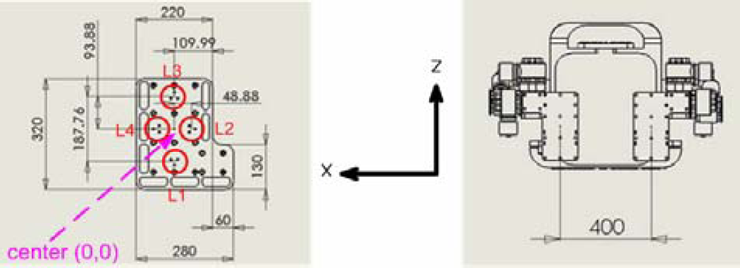
Location of loadcells on ALEX-I's foot
Location of 8 loadcells on ALEX-I's feet

In this project, PC104 and ARM7 LPC2138 are used as high and low level controllers respectively. Diagram of the controllers architecture is shown in Fig. 4(a). PC104 has 128 MB system memory and uses AMD Geode GX1, 300 MHz as the main processor. PC104 is approximately 0.097 Kg weight with A/D and RS232 extension modules.

(a) High and Low Level Controllers Architecture and (b) Controller Unit
ARM7 LPC2138 controllers from Phillips are used as low level controllers to control the joint positions of ALEX-I. These 32-bit microprocessors are based on RISC architecture with 512 KB flash memory. Many functions are available such as PWM, UARTS, SPI, I2C and ADC/DAC. The desired 16-bit set points are sent from PC104 (master) to 12 sets of ARM7 (slave) via parallel ports making the 12 low-level controllers receive the set points simultaneously. 74LS244 and 74LS373 are used as buffer and latch circuits respectively, for transferring data from high to low level controllers. 74LS154 is used as data selector to select the low level controller to receive the set point data. Photo of the controller unit is shown in Fig. 4(b).
The equation of motion of ALEX-I depends on the system parameters, such as link masses, moment of inertia, etc. The Euler-Lagrange equation of motion is written by
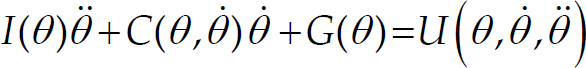
where I(θ)∈ ℝ
nxn
is the matrix of inertia, 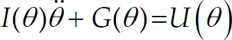
Fig. 5 shows the block diagram of ALEX-I position control. The outer loop controller is designed to track the ZMP reference trajectory based on GCP data sensed by the force plates in order to balance ALEX-I.

ALEX-I Control Loop Architecture
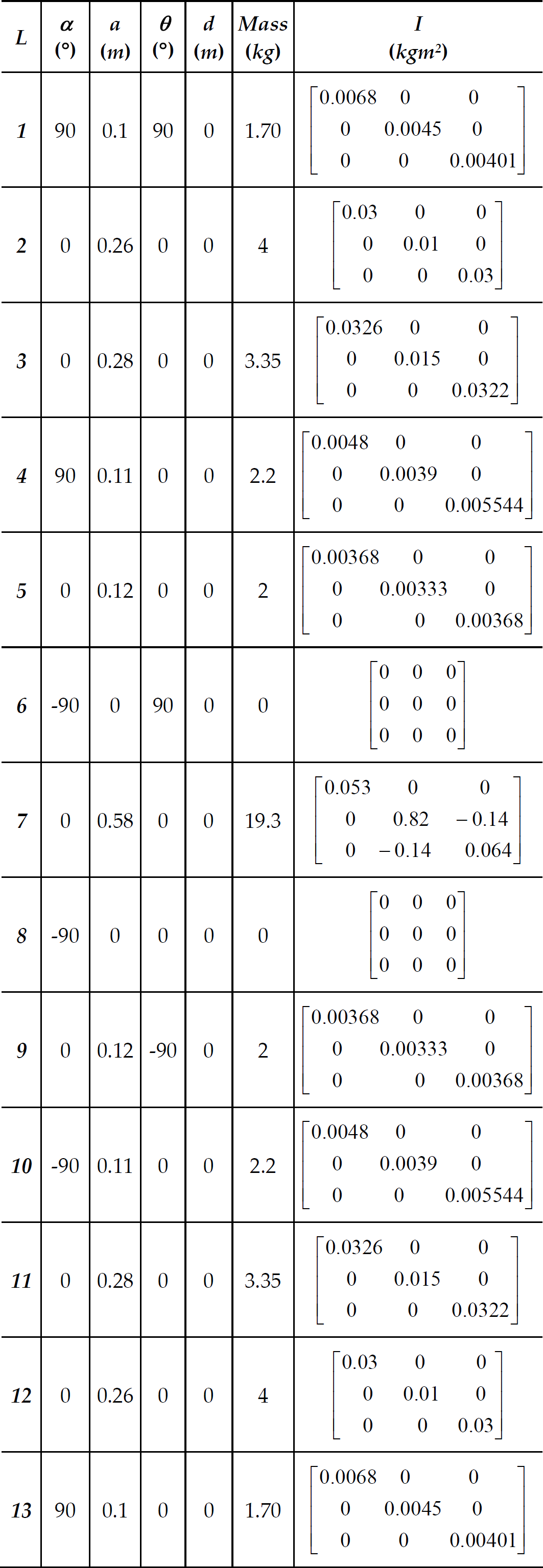
The matrix of inertia I, masses and the link properties of ALEX-I is summarized in Appendix I. The gravity G is 9.81 m/s2. The model is verified with Robotics Toolbox implemented by Corke (Corke, P. I., 2002) as shown in Fig. 6.
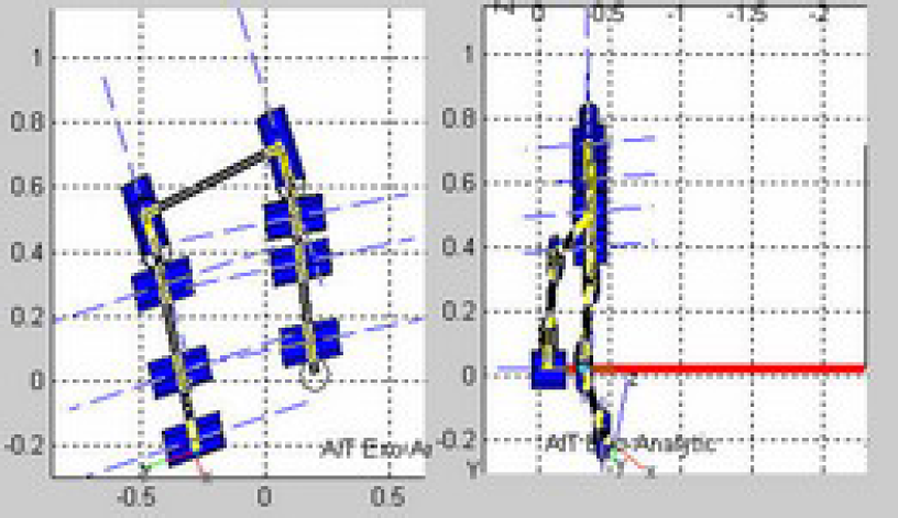
Verifying the ALEX-I properties with Robotics Toolbox
The gait cycle of ALEX-I based on ZMP criteria is determined and generated by SimMechanics Library in MATLAB. The walking gait cycle of ALEX-I is shown in Fig. 7. At the initial stage, the left foot is behind the right foot. ALEX-I firstly shifts the body center of mass (COM) to the supported right foot and then makes the left swing. The body COM is then shifted back to the supported left foot and then the right swing is made. After finishing the right swing, one gait cycle of walking completes. The ZMP set points obtained in MATLAB are then provided to ALEX-I. The ZMP of the gait cycle of a single step is shown in Fig. 8.

ALEX-I's Walking Gait Cycle

ZMP Reference for Single Step
Rebecca applied polynomial curve fitting to the gait data to obtain smooth walking motion of a biped robot (Rebecca, L. C., et al, 1995). ALEX-I also applies the polynomial curve fitting to generate the gait motion trajectory. A polynomial function is characterized by n+1 coefficient.

In this work, n = 2 and the polynomial function becomes
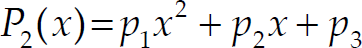
In the interpolation when x0 < x1 < x2 with the corresponding function values y0 < y1 < y2, the equation used in the interpolation is

This interpolation can be solved in MATLAB by providing the starting, middle and end points. The gait cycle shown in Fig. 7 is the interpolated data obtained from MATLAB and used in the experiment.
The Zero Moment Point (ZMP) is defined as the point on the ground where the net moment from the inertia and gravity forces is canceled, (Vukobratovic, M., et al, 2004). As long as the ZMP is inside the supporting region, the walking is considered dynamically stable. The ZMP is calculated from


For a feasible walking pattern, ZMP trajectories must lie within the supporting polygon defined by the locations and shapes of the supporting feet. If the entire ZMP trajectories are in the supporting area, of one foot area in single foot support or convex hull of the two feet in double feet support, that particular walking pattern is feasible. The stable boundaries for single foot and double feet are shown in Fig. 9.
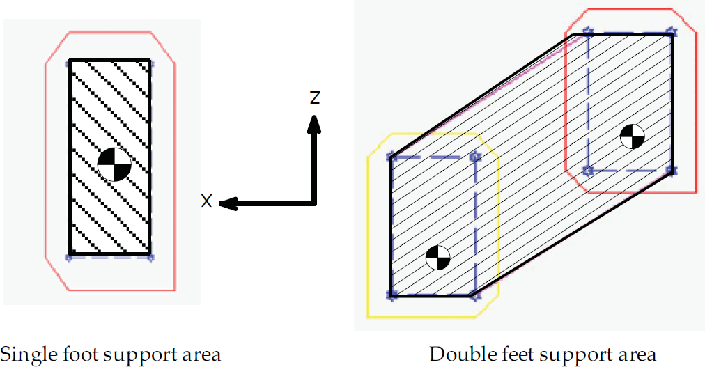
Stable Boundary for Single Foot Support and Double Feet Support
Obtaining actual ZMP of multi-joint exoskeleton is practically difficult since acceleration of all the links are required in the calculation. The Ground Contact Point (GCP) method is used instead to obtain the ZMP-like data. When the forces at known locations are measured by loadcells, the GCP (x, z) can be calculated by


During single foot support, the GCP of the supporting foot is also the ZMP of the whole exoskeleton. The GCP is described as


During double feet support, the GCP becomes
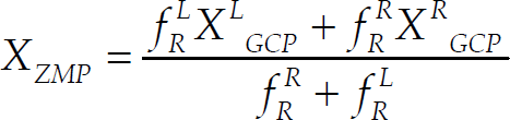
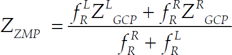
where R and L refers to right and left feet of ALEX-I respectively.
GCP is sensed by force plates. The ground reaction force (f R ) measured by the loadcell is amplified by instrument amplifier INA126 and fed to 10 bits A/D: PCM3718 card of PC104. The pre stresses of the 8 loadcells are calibrated and programmed in PC104. GCP data acquisition circuit is shown in Fig. 10.

Loadcell Data Acquisition
In order to balance the leg exoskeleton, ZMP error compensation is necessary. In this paper FLC is designed based on the Jacobian analysis of the system. The ZMP's position, p
ZMP
= [x y z] of a rigid multi-links system is a general function of the system's joint angles θ.

The ZMP differentiation can be determined from the multiplication of Jacobian matrix with joint angle differentiation. Where the Jacobian matrix, is defined as

Since the ZMP always locates on the ground and only moves in the horizontal x-z planes, the Jacobian matrix thus becomes

Upon the analysis of the Jacobian matrix and the couples between x-axis and z-axis are found small and negligible. Thus Jacobian matrix of ALEX-I is expressed by

The ZMP of x and z axis is decoupled into 2 functions on different axis.


Where
Ax = ((−s1c234s5c6 + c1c5c6) - s1s234s6) Bx = ((−s1c234s5s6 + c1c5s6) - s1s234c6) Cx = (s1c234c5 + c1s5) Dx = (s1c234c5 - c1s5) Ez = (s234s5c6 - c234s6) Fz = (s234s5s6 - c234c6) Gz = (s234c5) s
i
=sin(θ
i
), c
i
=co’θ
i
) s123 = sin(θ1 + θ2 + θ3) c1c2c3 =co’θ1)cos(θ2)cos(θ3) l
cxi
,l
cyi
,l
czi
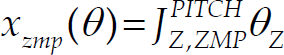
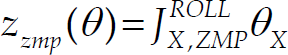
: center of mass of the associated link i (i = 1, 2,…, 13). The parameters are given in Appendix II. From equations (20)–(21), location of ZMP on x or z axis can be controlled separately on selected roll (23) and pitch (25) joints.
PD controller is used in the inner loop, the joint position control, while ZMP based FLC (ZMP-FLC) is used in the outer loop, the balancing control of ALEX-I. Encoders are used to sense the joint positions while loadcells are used to determine the GCP. FLC is proposed and designed based on the Jacobian analysis, where ZMP is decoupled and controlled separately in x and z axes as stated from equations (20)–(21). Fig. 11 shows the block diagram of the proposed ZMP-FLC for balancing control of ALEX-I.

Block Diagram of ZMP-FLC
PD controller is used to control each joint individually. The set points of 12 joints with 16-bit resolution are sent from PC104 to AMR7 controllers. These set points are the required balanced posture of ALEX-I. In the inner loop, PD controller is used for tracking the set point, θ
d
. The PD controller output U(s) is calculated from

1024 pulses per revolution incremental encoder is used as the position sensor at each joint. LS7366 from LSI, is used to obtain the quadrature A/B of the incremental encoder signal. This IC communicates with ARM7 processor through SPI and increases the quadrature counting four times. It increases the resolution of the encoders to 4096 pulses per revolution. The block diagram of the inner loop PD control is shown in Fig. 12(a).

(a) Inner Loop PD Controller, and (b) Outer Loop Fuzzy Logic Controller
FLC has been widely used to model a nonlinear mapping between input and output. The FLC algorithm for balancing control of ALEX-I is based on ALEX-I's ZMP trajectory. Block diagram of the outer loop controller of ALEX-I is shown in Fig. 12(b).
FLC is applied to the system to compensate when the GCP reading deviates from the ZMP reference. The fuzzy rule consists of a set of antecedent-consequent linguistic rules of the form

The position error in x-axis (e x ) and in z-axis (e z ) consist of 5 membership functions each; negative big (NB), negative medium (NM), zero (Z), positive medium (PM) and positive big (PB). ZMP-FLC is used to adjust the ankle roll and pitch joint angles to maintain the balanced posture of ALEX-I. All the membership functions are illustrated in Fig. 13. The rules of the ZMP-FLC are given in Tables 2–5.

Membership Function of x and z axes Errors (e x , e z ) and Membership Function of Ankle Joints Angles (θ1, θ12, θ2, θ11)
The Fuzzy Rules for θ1: Left Ankle (z-axis)

The Fuzzy Rules for θ12: Right Ankle (z-axis)

The Fuzzy Rules for θ2: Left Ankle (x-axis)
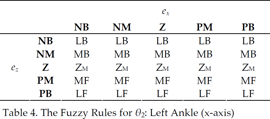
The Fuzzy Rules for θ11: Right Ankle (x-axis) where
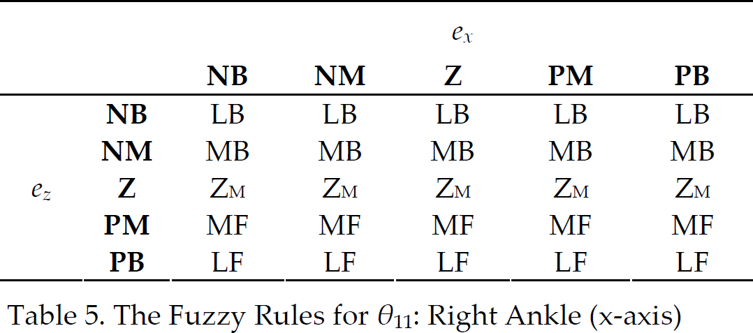
LLS = Large Left Side, LRS = Large Right Side, LB = Large Backward, LF = Large Forward, ZM = No Movement MLS = Medium Left Side, MRS = Medium Right Side, MB = Medium Backward, MF = Medium Forward, and
In this work, triangle and trapezoid membership functions are applied for the input and singleton membership functions are applied for the output. The center of gravity method defined for singleton (COGS) is used to defuzzify the output, u
FLC
.

where s
i
is the position of the singleton i of the output, and μ(s
i
) is the firing strength of rule i. μ(s
i
) is the overall truth value of premise of i and obtained from (39). A
i
1 (e(x)) and A
i
2 (e(z)) are the truth values of the errors in x-axis and z-axis respectively. These truth values are calculated from (40),

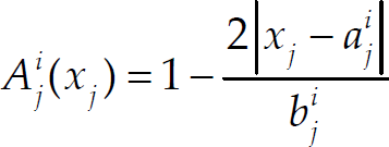
x j is the input value, a i j and b i j are the center and the width (range) of triangle membership function respectively as shown in Fig. 14.

Triangle Membership Function
In balancing control by ZMP-FLC, GCP is sensed continuously from the force plates. The GCP is compared with the ZMP reference, and then the compensated angles from FLC are given to the ankle joints.
In order to evaluate the performance of the ZMP-FLC, crouching posture as shown in Fig. 15 is used to test the gait posture motion. Crouching posture is simulated and the ZMP reference data is determined from MATLAB and used later in the experiment.

Crouching Posture
Fuzzy toolbox in MATLAB is applied on ALEX-I model. The fuzzy rules are based on the difference of ZMP and GCP data of ALEX-I. The 4 outputs are the compensated angle to ankle joints (θ1, θ12, θ2, θ11) in order to maintain ALEX-I in the stable convex hull region of the supporting area.
To test the robust performance of the proposed algorithm, disturbances of 4 ankle joints (roll and pitch) are applied. The disturbance with the magnitude ±15° is applied to the joints to cause instability. Fig. 16(a) shows the GCP of ALEX-I moves out of the convex hull region, and ALEX-I would fall when ZMP-FLC is disabled. When ZMP-FLC is enabled, Fig. 16(b) shows that the GCP lies within the convex hull region under the same disturbance is applied.

GCP Trajectory (a) Without ZMP-FLC and (b) With ZMP-FLC
The surface plots of the 4 outputs based on x-z errors of the ZMP and GCP are shown in Fig. 17. From the plots, θ1 and θ12 that control the ankle roll plane are zero when the error in x axis is zero. On the other hand, θ2 and θ11 that control the ankle pitch plane are zero when the error in z axis is zero.

Surface plots of ZMP-FLC
The proposed ZMP-FLC is written in C language and programmed on PC104. The experiment is conducted as shown in Fig. 11. In the experiment, human model is used instead of the real patient, where the load can be added to the model.
Without the ZMP-FLC, ALEX-I fell down due to the disturbances from backlash and tolerance at the joints of ALEX-I. ZMP-FLC is then applied to track the reference ZMP and also to overcome the disturbances. Fig. 18 shows ALEX-I on the tracking of reference ZMP for the crouching posture. With the ZMP-FLC, ALEX-I is able to perform stable crouching posture without falling down. Fig. 19 illustrates the ZMP reference against GCP data of ALEX-I under crouching posture. The oscillation of the tracking is due to the compensation of the ankle joints while trying to maintain the reference posture.

Experiment on ALEX-I (a) Without ZMP-FLC and (b) With ZMP-FLC

ZMP Reference and GCP under Crouching Posture
In this paper, ZMP-FLC was applied to a leg exoskeleton, ALEX-I. ALEX-I applied the GCP method based on ZMP concept to balance the stability of the system. The FLC is proposed and designed based on computation of Jacobian analysis of ALEX-I.
FLC with 25 rules (2 inputs and 4 outputs) is applied to the main controller on PC104. In the simulation, disturbance was applied to the x-z axis to move GCP out of the convex hull region. With the proposed ZMP-FLC algorithm, ALEX-I could balance the stability, GCP is still lying within the boundary of the supporting area. The algorithm is then applied to the real ALEX-I. By considering backlash and joints tolerance as the disturbance, ALEX-I could maintain the stability and not fall down in a crouching posture.
Footnotes
7. Acknowledgments
This research is financially supported by National Electronics and Computer Technology Center (NECTEC), Thailand.
Appendix I: Links' Properties
| L | α (°) | a (m) | θ (°) | d (m) | Mass (kg) | I (kgm2) |
|---|---|---|---|---|---|---|
|
|
90 | 0.1 | 90 | 0 | 1.70 | |
|
|
0 | 0.26 | 0 | 0 | 4 | |
|
|
0 | 0.28 | 0 | 0 | 3.35 | |
|
|
90 | 0.11 | 0 | 0 | 2.2 | |
|
|
0 | 0.12 | 0 | 0 | 2 | |
|
|
−90 | 0 | 90 | 0 | 0 | |
|
|
0 | 0.58 | 0 | 0 | 19.3 | |
|
|
−90 | 0 | 0 | 0 | 0 | |
|
|
0 | 0.12 | −90 | 0 | 2 | |
|
|
−90 | 0.11 | 0 | 0 | 2.2 | |
|
|
0 | 0.28 | 0 | 0 | 3.35 | |
|
|
0 | 0.26 | 0 | 0 | 4 | |
|
|
90 | 0.1 | 0 | 0 | 1.70 |
Appendix II: Links' COM locations

| COM (mm) | ||||
|---|---|---|---|---|
| x | y | z | ||
|
|
0 | 0 | 0 | |
|
|
37 | 0 | 14 | |
|
|
107 | 1 | 4 | |
|
|
135 | 0 | 4 | |
|
|
33 | 0 | 0 | |
|
|
0 | 25 | 0 | |
|
|
290 | 75 | 0 | |
|
|
|
0 | 0 | 61 |
|
|
0 | 72 | 0 | |
|
|
150 | 0 | 4 | |
|
|
150 | 0 | 4 | |
|
|
63 | 14 | 0 | |
|
|
51 | 79 | 51 |