
Abstract
This paper describes the control architecture of a 10 DOF (Degrees of Freedom) lower limbs exoskeleton for the gait rehabilitation of patients with gait dysfunction. The system has 4 double-acting rod pneumatic actuators (two for each leg) that control the hip and knee joints. The motion of each cylinder's piston is controlled by two proportional pressure valves, connected to both cylinder chambers.
The control strategy has been specifically designed in order to ensure a proper trajectory control for guiding patient's legs along a fixed reference gait pattern.
An adaptive fuzzy controller which is capable of compensating for the influence of the dry friction was successfully designed, implemented and tested on an embedded real-time PC/104.
In order to verify the proposed control architecture, laboratory experiments without a patient were carried out and the results are reported here and discussed.
1. Introduction
Rehabilitation robotics is a special branch of robotics which focuses on machines that can be used to help people recover from severe physical trauma. A major area of work within the field of rehabilitation robotics, especially over recent years, has looked to the use of robotic devices to assist in therapeutic interventions.
Robotic devices can be valuable tools in therapies that involve repetitive and task-oriented movement training, such as gait training. They open the possibility of guiding the patient's limbs in a very accurate and reproducible way during gait training, which is hard to accomplish by manual therapy. Moreover, the use of robotic devices offers the possibility of quantifying each patient's specific impairments and his/her progress during treatment. This can be done by using sensitive and objective measures of movement performance, such as speed and smoothness of movement.
From a healthcare costs perspective, robotic devices can also reduce the economic burden on a country's healthcare system because only one therapist is used for the observation of the patient during training, while manual therapy often requires multiple therapists to properly administer it.
Often, robotic devices are used together with a body weight supported (BWS) treadmill system [1],[2],[3],[4],[5]. A BWS treadmill system consists of a treadmill and a mounting frame, with a suspension system and a harness used to remove a controllable portion of the weight from patients' legs, providing stability to the trunk and safety to the patient while walking on the treadmill. The BWS system unloads body weight symmetrically from the lower limbs as they move forward. The movement is provided by a slow moving treadmill. The treadmill's constant rate of movement provides rhythmic input, which reinforces a coordinated reciprocal pattern of movement. The BWS system reduces the demand placed upon muscles, which may enable the patient to work on improving the coordination of the movement while gradually increasing the strength of the muscles. The controlled environment may also increase patient confidence by providing a safe way to practice walking. As patients progress, the BWS can be gradually decreased, challenging the patient to assert more postural control and balance [6].
BWS therapy is based on the theory that locomotion is controlled by a network of neurons located in the spinal cord, known as the central pattern generator (CPG). The CPG is believed to produce rhythmic, patterned outputs without continuous input from the brain. The evidence for this view originated from the treadmill gait training of animals with a complete spinal cord injury [7],[8].
Clinical studies confirmed that retraining the gait with robotic systems leads to a more successful recovery of ambulation with respect to the over-ground walking speed and endurance, movement coordination, and other important gait characteristics, such as symmetry, stride length and double stance time [9],[10]. There are also reports of reductions in spasticity [11] and increases in cardiopulmonary efficiency [12] after body weight–supported locomotor training. It has also been found that robotic therapy combined with conventional therapy is more effective than conventional therapy alone in severely affected patients [13].
Many robotic systems have been developed with the aim of automating and improving the rehabilitation training of patients with lower limb impairments. Usually, the systems that use a BWS treadmill training approach have an exoskeleton structure [1], [3], [5]. For the purposes of the present work, we define an exoskeleton as a mechanical device that is essentially anthropomorphic in nature, ‘worn’ by an operator and fitting closely to the body, working in concert with the operator's movements.
Exoskeleton designs can be classified in terms of their assistive capabilities as either passive or active devices.
Passive devices mainly assist human users by helping them to employ their own power without supplying energy to the user. Several rehabilitation passive devices are reported in the literature. For example, the system developed by Walsh et al. [14] uses passive devices like springs to store energy released during negative-work phases of the gait cycle and releases it during the positive-work phases to assist. Another passive system is that of leg orthosis, designed to assist people with hemiparesis to walk through the elimination of the effects of gravity [15]. It is only composed of links and springs, which completely balance the effect of gravity over the range of motion. Usually, passive devices are perceived by patients as being more comfortable and safer than active ones.
In order to be able to assist lower-limb motions during gait rehabilitation, robot devices must be capable of active behaviour. They should assist the elevation of the centre of mass of the body (CoM) during walking in a repetitive manner. For active assistance during gait rehabilitation, drive selection constitutes one of the key issues, since human joints require high torques during gait but, at the same time, aesthetic issues require compact and low weight drives. Three different types of actuators can be used: hydraulic cylinders, electrical motors and pneumatic actuators (pneumatic cylinders or artificial muscles).
Prototypes that use electrical or hydraulic actuators tend to be complex and expensive. Compared to these, pneumatic actuators can provide certain important advantages, such as: low-cost, a high power-to-weight ratio, long duration, ease of maintenance and cleanliness. Moreover, the choice of adopting pneumatic actuators to actuate the joints is biologically inspired. They provide linear movements and are actuated in both directions, such that the articulation structures do not require the typical antagonistic scheme associated with biological joints. Because of these characteristics, it was decided to use pneumatic actuators for the rehabilitation robot system developed in the Laboratory of Applied Mechanics at DIIIE of University of L'Aquila, as presented in this work. However, pneumatic systems exhibit highly nonlinear behaviour which is associated with the compressibility of air and the presence of friction in the cylinder and in the valves [16, 17]. Because of all these characteristics, it was decided to use fuzzy logic as a control technique.
This paper describes the control architecture for the developed prototype. This control architecture should ensure the guidance of the patient's legs along a fixed reference gait pattern. In order to verify the proposed control architecture, laboratory experiments without a patient were carried out and the results are reported and discussed.
2. Exoskeleton structure
Designing robotic devices with an exoskeleton structure represents one of the most challenging areas of robotics research, requiring significant advances in materials, mechanisms, electronics, sensors, controls, intelligence, communication, power sources and actuation. However, we believe that exoskeletons have the potential to make an impact in the emerging field of the lower extremity gait rehabilitation of motor-impaired patients. For the purposes of the present work, we define an exoskeleton as a mechanical device that is essentially anthropomorphic in nature, ‘worn’ by an operator and fitting closely to the body, while working in concert with the operator's movements. The exoskeleton design must be flexible, to allow both upper and lower body motions once a subject is in the exoskeleton, since walking involves a synergy between upper and lower body motions. An exoskeleton must be adjustable to the anatomical parameters of a subject; it must also be lightweight, easy to wear and guarantee comfort and safety [18].
The robot system for the rehabilitation of lower limbs presented in this work satisfies these requirements. The structure consists of three basic parts: a pelvis, a dorsal bar and limbs, made up of three links corresponding to the thighbone, the shinbone and the foot. On the dorsal bar, a corset worn by the patient is connected.
Following the calculations of human body parts, the exoskeleton elements have the following dimensions (Fig.1):
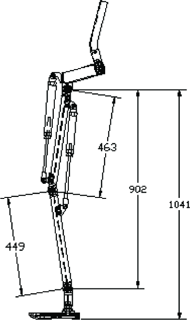
Dimensions of the realized exoskeleton parts
The structure of the exoskeleton is realized in aluminium, which ensures a light weight and good resistance. The degrees of freedom - all rotational - are: number 1, with an axis perpendicular to the front, numbers 2, 3 and 4, with axes perpendicular to the sagittal plane, number 5 with an axis perpendicular to the ground. Of these, only DOFs 2 and 3 are motorized (Fig.2).
The robot moves parallel to the skeleton of the patient, so that no additional DOF or motion ranges are needed to follow the patient's motion. The rehabilitation system is actuated by 4 pneumatic actuators, two for each inferior limb of the exoskeleton. The motion of each cylinder's piston is controlled by two proportional pressure valves connected to both cylinder chambers. Rotational potentiometers are used to obtain hip and knee angles.

Degrees of freedom (DOF) of the exoskeleton
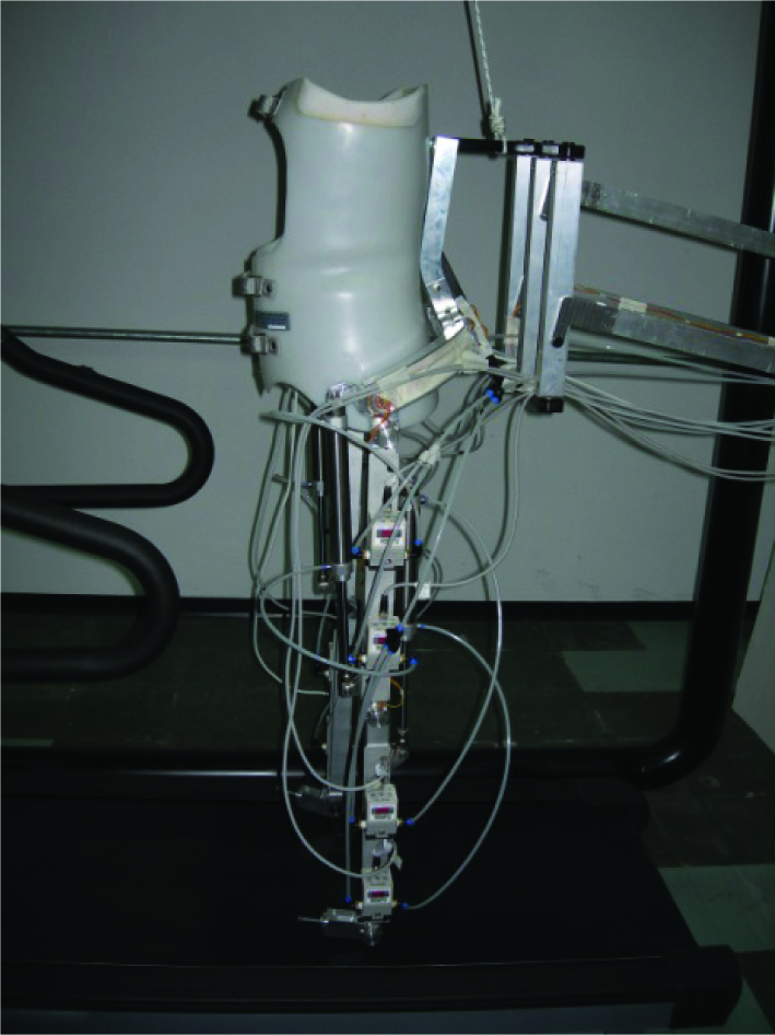
The overall exoskeleton structure is positioned on a treadmill and supported, at the pelvis level, with a space guide mechanism that allows vertical and horizontal movements. The space guide mechanism is connected with the chassis equipped with a weight balance system (Fig.3).

Realized prototype of the overall rehabilitation system
3. Kinematic analysis
3.1 Forward kinematics
The forward kinematics problem is concerned with the relationship between the individual joints of the exoskeleton limb and the location and orientation of the limb's end point (the ankle joint in our case). The forward kinematic analysis should be performed in order to define those limb and joint positions and motions which are needed to perform the dynamic analysis of the mechanical system. Moreover, the forward kinematic analysis is applied for obtaining the error between the real position and the desired position of the end point as a feedback in the control process.
Defining the exoskeleton limb as a two link robot manipulator with 2 DOF, we have used the Denavit-Hartenberg (D-H) convention to describe the translational and rotational relationship between adjacent robot links. With this approach the direct kinematics problem is reduced to the problem of computing a chain of two 4×4 homogeneous link transformation matrices.
Each homogeneous transformation Ai is represented as a product of four basic transformations (Eq. 1):

where the four quantities θi, ai, di and αi are parameters associated with link i and joint i. The four parameters are: ai - link length; αi - link twist; di - link offset; θi - joint angle.
Thus, the homogeneous transformation matrix 0Ti, which specifies the position and orientation of the i-th coordinate frame with respect to the base coordinate system, is the chain product of successive homogeneous link transformation matrices of i−1Ai, as expressed in Eq. 2:

First the base frame o0x0y0z0 has been established as shown in Fig. 4, choosing the origin at the hip joint point.
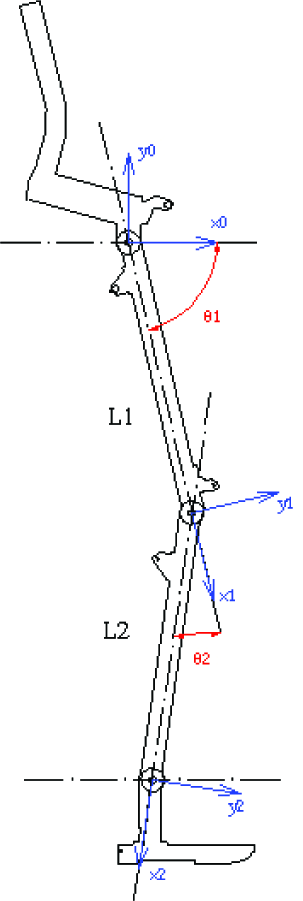
Denavit-Hartenberg representation of the developed robot exoskeleton system
Once the base frame is established, the o1x1y1z1 and o2x2y2z2 frames are fixed by the D-H convention, where the origins O1 and O2 have been located at the end of links 1 and 2, respectively. The link parameters are shown in Table 1.
Link parameters for a 2-link robot limb

The A-matrices are determined as in Eq. 3 and Eq. 4:


The T-matrix is thus given by Eq. 5:

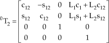
Introducing the following notation ci = cosθi, c12 = cos(θ1 + θ2), s12 = sin(θ1 + θ2) and θ12 = θ1 + θ2, the 0T2 matrix can be written as (Eq. 6):
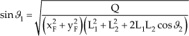
Accordingly, knowing the link dimensions and joint rotation angles, the xF and yF components of the origin O2 of the base frame are defined by Eq. 7:

To facilitate the controller design, and knowing the position of the ankle joint and using the known geometry of the exoskeleton, the actuators' lengths in this position are determined using simple trigonometric relations.
3.2 Inverse kinematics
The inverse kinematics problem is instead concerned with finding the joint variables in terms of the end-effector's position and orientation. The general problem of inverse kinematics can be stated as follows. Given a 4×4 homogeneous transformation:

One or more solutions of Eq. 9 should be found:

The correct evaluation of the inverse kinematic analysis is of vital importance in order to compute the correct joint parameters because the exoskeleton robot is controlled in a task space.
Consider the two-link planar limb shown in Fig.5.
In this case, only two parameters are required to specify the complete two-dimensional configuration of the end-effector of such a manipulator, namely the position vector [xF, F]. We also introduce Ψ, where Ψ is the orientation of link 2 in the plane (Fig. 5). Hence, rather than giving a general 0T2 as a goal specification, we will assume a transformation with the structure:
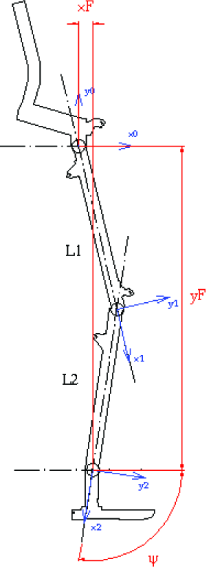
Denavit-Hartenberg representation of the developed robot exoskeleton system

All of the attainable goals must lie in the subspace implied by the structure of equation (10). By equating (6) and (10), we arrive at a set of four nonlinear equations which must be solved for θ1 and θ 2 :

Considering the known trigonometric equations, the last system can be rewritten as:

Solving the system, we obtain:

where:

In order for a solution to exist, the right hand side of (13) and (14) must have a value between −1 and 1. Physically, if this constraint is not satisfied, then the goal point is too far away to be reached by the lower limb's ankle joint.
One can also observe that the solution of Eq. 13 is not unique, which means that the same position of the lower limb's ankle joint can be reached for two different configurations, as shown in Fig. 6.

Two different solutions for opposite values of θ2
This problem of indeterminacycan be resolved by considering the requirements for biologically inspired movements, according to which the following constraint for θ2 can be applied 70° ≤ θ2 ≤ 180°.
This will guarantee the unique solution of the inverse kinematics problem, i.e., for known values of the end-effector's position (xF, yF) as well as the links' lengths L1, L2.
Using the known geometry of the exoskeleton, the actuators' lengths in this position can be very easily determined using simple trigonometric relations.
3.3 Obtaining the end-effector's reference position
To obtain the end-effector's reference position, the human walking gait was analysed using a camera-based motion capturing system. The motion capturing of a healthy subject walking on the treadmill was performed in our laboratory using a single video camera placed with an optical axis perpendicular in respect of the sagittal plane of the gait motion. The video camera Panasonic Nv-gs400eg with 4.0 MPixel, 3CCD, the Leica Dicomar objective and a focal distance of 3.3mm was positioned as far as possible from the treadmill in order to reduce the perspective effects (in our case that distance was L=13m) (Fig. 7). Three markers mounted on a subject's hip, knee and ankle were filmed and tracked. Inside the filming zone, an object with known dimensions (grid) was placed and it was used as a reference to transform the measurement from pixel to distance measurement units.
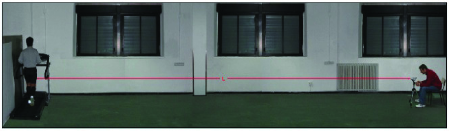
Movement analyses setup
The recorded video was post-processed and the kinematics movement parameters of the limbs' characteristic points (the hip, knee and ankle) were extracted. The obtained trajectory for the end-effector's position (i.e., the ankle marker) is shown in Fig. 8.

Trajectory of the ankle joint relative to the hip joint
Considering the obtained trajectory, by the means of the Working Model 2D software (Fig. 9), the target lengths of the actuators were determined for each trajectory point during the gait cycle.

Model of the exoskeleton system with the user and actuators' length, created with the WorkingModel 2D software
4. Control architecture
To satisfy the demand for the efficient control of the developed rehabilitation system, the controller should be designed so as to enable the accurate and repetitive point-to-point tracking of the reference trajectory by the lower exoskeleton limbs' ankle joint.
During the process of controller's design, the nonlinear characteristics of the pneumatic actuators - especially the nonlinear friction and the thermodynamic characteristics of the air pressure in the chambers of the cylinders - must be taken into account. In addition, a series of nonlinear and time-varying factors such as load force, temperature, position of the piston, staying-time while still and wearing out during the working procedure, should also be considered. All of these characteristics have a strong, negative influence on the control accuracy of the cylinder's rod displacement, and the linear control algorithms cannot guarantee the needed control precision.
In order to cope with the nonlinearities and enable its robustness and adaptability, a control system based on fuzzy logic is proposed.
4.1 Design of an adaptive fuzzy controller
Several considerations and assumptions were taken into consideration prior to designing the controller:
The controller should aim to regulate the lengths (i.e., the rod displacement) of the thighbone and shinbone pneumatic actuators;
The zero reference position for calculating the cylinder's rod displacement should correspond to completely retracted rod;
The piston rod chamber is denoted as the anterior chamber and the other one as the posterior chamber;
The rod displacement error is positive if the reference displacement is greater than the real displacement;
The rods' displacement ranges are 0-180cm and 0-160 for the thighbone and shinbone cylinders respectively. Since the working area of both cylinders is overlapping, the same interval 0-160cm is used for both of them.
The maximum rod velocity is 5 m/s and the valves' command voltage range is 0-10V.
The design of the architecture of the system controller is presented by the diagram in Fig. 10.

Architecture of the control system
The starting point of a controller design is to choose the input and output signals. The former accounts for the state of the system while the latter corresponds to the control actions to be performed on the system.
In our case, there are two input signals: the displacement error e(kT) and the error change rate de(kT), defined as:

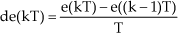
where r(kT) is the reference actuator's length, l(kT) is the measured actuator's length for a given trajectory point and T is the sampling period. The controller has two output signals uANT(kT) and uPOS(kT) which are the control voltages of those valves connected to the anterior and posterior cylinder chambers, respectively.
To make the controller adaptive for the dynamic characteristics of the controlled system, all of the input and output signals were normalized by introducing the following scaling factors Se, Sde, SuANT and SuPOS:

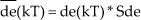

The values of the introduced scaling factors were experimentally determined. The experimental work has shown that the proportional scaling factor Sde has the most significant influence on the pneumatic actuators -namely, it determines the speed of the cylinders' rods. To achieve a good trade-off between the high reactivity of the actuators on the one hand and the reduction of the settlement time and overshoot at each of the reference points on the other, this factor was selected as Sde=0.085.
Two input and two output linguistic variables E, DE and UANT, UPOS, corresponding to the input and output signals, are defined as the input and output of the fuzzy controller. The input linguistic variables are defined in the domain of Di=[−1 1] and the output in the domain Do=[0 1], as follows:


The membership functions for the input and output variables are illustrated in Fig. 11, Fig. 12 and Fig. 13.

Membership functions of the normalized fuzzy input variables E and DE
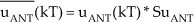
Membership functions of the normalized fuzzy output variable UANT
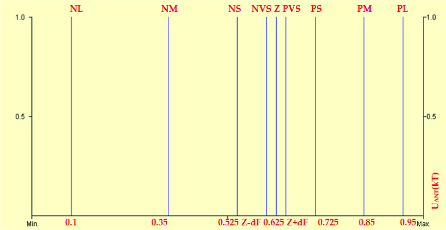
Membership functions of the normalized fuzzy output variable UPOS
The rules of the fuzzy algorithm are presented in a matrix format, as shown in Fig. 14.

Main rule database for the Fuzzy controller
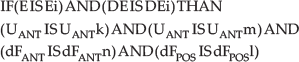
The rules should be interpreted as follows:

As one may observe, the NVS and PVS values of the output membership functions are parametrically defined. This is in order to cope with the dry friction of the pneumatic actuators, which has a strong negative influence on control accuracy. To better understand the dependency upon the dry friction, experimental trials with the cylinder while horizontally placed were conducted. It was determined that if the pressure difference between the cylinder chambers is below 80kP (which corresponds to 0.87V of any difference), the rod will remain still. Since the dry friction changes with the working conditions, the parameter dF should be tuned to change the controller's transform characteristic and to adapt it to the working conditions. This parameter is the same for both output variables and is also modelled using the fuzzy variable dF(kT), as shown in Fig. 15.

Membership functions of the normalized parameter dF
This parameter varies as a function of E(kT) and DE(kT), and the rules of the fuzzy algorithm are presented in a matrix format, shown in Fig. 16.

Rule database for the additional Fuzzy controller for the adaptive parameter dF
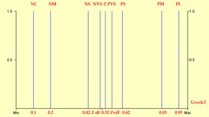
The adaptability of controller parameter dF will be implemented within the same controller using the same fuzzification and inference modules. Therefore, only an additional partial conclusion will be added to the conclusion of the inference in the controller:
The max-min algorithm is applied and the centre of gravity (CoG) method is used for defuzzification. Since the working area of the cylinders overlaps, the same fuzzy controller is used for both of them.
4.2 Controller implementation
The control algorithm was implemented in embedded VC++ and runs inside an embedded PC104. The PC104 is based on the Athena board from Diamond Systems, with the real-time Windows CE. Net operating system, which uses the RAM-based file system. The Athena board combines the low-power Pentium-III class VIA Eden processor (running at 400 MHz) with on-board 128 MB RAM memory, 4 USB ports, 4 serial ports, and a 16-bit low-noise data acquisition circuit, into a new compact form factor, measuring only 4.2″ × 4.5″. The data acquisition circuit provides high-accuracy, stable 16-bit A/D performance with a 100 KHz sample rate, wide input voltage capability up to +/− 10V and programmable input ranges. It includes 4 12-bit D/A channels, 24 programmable digital I/O lines and two programmable counter/timers. A/D operation is enhanced by on-board FIFO with interrupt-based transfers, internal/external A/D triggering and an on-board A/D sample rate clock.
The PC104 is directly connected to each rotational potentiometer and valves placed onboard the robot.
In order to increase the real-time performances of the control algorithm, the processing of the inputs and the generating of the outputs was parallelized in four different threads (one thread per actuator).
5. Experimental evaluation
To evaluate the performance of the exoskeleton structure together with the proposed control architecture, experimental tests without patients were performed.
During the gait training, one of the most important goals is to achieve path repeatability. In order to test the path repeatability, the ISO 9283 standard was used. According to this standard, path repeatability expresses the closeness of the agreement between the attained paths for the same command path followed n times in the same direction. Path repeatability is expressed by RTp-the maximum RTpi, which is equal to the radius of a circle in the normal plane with its centre on the barycentre line (Fig. 18).
Experimental setup
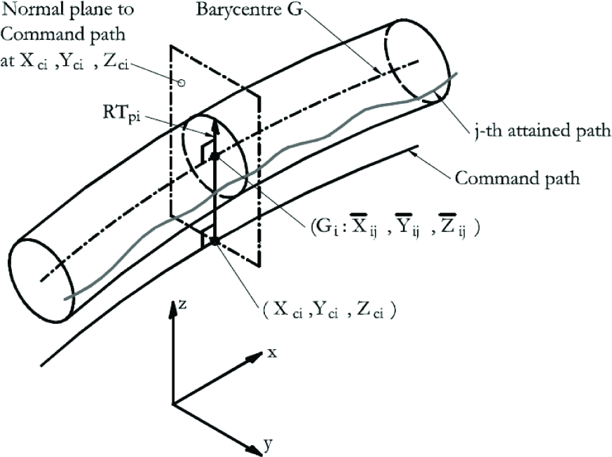
Target and experimentally obtained thighbone actuator length during the gait cycle (RT represents repeatability; G represents the barycentre of a cluster of attained poses; Xci, Yci and Zci are the coordinates of the i-th point of the command path; Xij, Yij and Zij are the coordinates of the intersection j-th attained path and the i-th normal plane)
The path repeatability is calculated as follows:

where:


m is the number of calculated points along the path and n is number of measurement cycles.
Ten tests, with ten cycles without load (the only load was the weight of the exoskeleton structure) for the same command path were conducted. All of the trials were conducted with a sampling frequency of 10 kHz and a pressure of 0.6 MPa. The values for path repeatability were calculated and the corresponding results for all tests are shown in Table 2.
Repeatability results

During all the experiments, the movement was natural and smooth while the limb moved along the target trajectory. The target and experimental ankle joint trajectory, obtained by averaging 10 different cycles, are shown in Fig.19.

Target and experimentally obtained trajectory of the ankle joint during the gait cycle
The results from the experiments, at a confidence level p=0.05, have shown that the maximum absolute error is 3.5mm, which has no significant impact on the rehabilitation process and can be treated as an acceptable result.
6. Conclusion
A fuzzy controller was used to regulate the lengths of the pneumatic actuators of a 10 DOF lower limbs exoskeleton for gait training, and was developed and verified with the experiments. The experimental results show that the developed control architecture can be considered to be an appropriate option for the control of the developed prototype. With the developed controller, accurate trajectory control and the high robustness of the system were achieved. Fuzzy control has also been demonstrated to provide highly satisfactory results in terms of accuracy and repeatability.
With these experiments, the first phase (experiments without a patient) was concluded. Our future work foresees two more steps for the evaluation of the system: experiments with healthy volunteers and experiments with disabled patients.
In addition, visual biofeedback of the patient's gait performance is planned to be implemented. The visual display, showing the gait trajectory in real-time, will help the patient to adapt his/her walking with the reference gait pattern.