
Abstract
This paper addresses the control problem of inspecting underwater pipeline on the seabed, with coordinated multiple autonomous underwater vehicles in a formation. Based on the leader-follower strategy, the dedicated nonlinear path following controller is rigorously built on Lyapunov-based design, driving a fleet of vehicles onto assigned parallel paths elevated and offset from the underwater pipeline, while keeping a triangle formation to capture complete 3D images for inspection. Due to the spatial-temporal decoupling characteristics of individual path following controller, the velocities of the followers can be adapted in the coordinated control level, only relying on the information of generalized along-path length from the leader, in order to build the desired formation. Thus, the communication variable broadcast from the leader is kept to a minimum, which is feasible under the severely constraints of acoustic communication bandwidth. Simulation results illustrate the efficiency of coordinated formation controller proposed for underwater pipeline inspection.
Keywords
Introduction
With more and more concern about the abounding and valuable ocean resources, the past thirty years have witnessed a remarkable growth in the wide range of underwater activities. The commercial offshore oil and gas industries have been one of the major drivers for underwater technology, and remotely operated vehicle (ROV) became a well-established technology frequently used in the offshore industry (Ontin, M., 1998). More recently, as the oil and gas production move to greater depth, the appeal to advanced underwater technology increases, especially to the control technology of autonomous underwater vehicle (AUV) which is free from the constraints of an umbilical cable (Yuh, J., 2001). Furthermore, as a fleet of AUVs dealing with a variety of tasks provides significant advantages, such as flexibility, robustness and efficiency, beyond what are possible with single vehicle, there are much more interests to employ multiple AUVs for underwater activities (Stilwell, J. & Bishop, E., 2000) and (McDowell, P. et al., 2002).
One meaningful application of multiple AUVs is to inspect underwater oil pipeline (Chance, T. C. et al., 2001) and (Vestgård, et al. 2001), as depicted in Fig. 1. In this case, three AUVs are required to fly above the pipeline at identical or different depths along parallel paths, and map the pipeline using three copies of the same suite of vision sensors, to inspect the same scene from three different viewpoints capturing 3D images of the pipeline. Moreover, by requesting a specific formation of these vehicles to traverse parallel paths to make the overlap of vision coverages on the pipeline, no pieces of the pipeline will be omitted (Pascoal, A., 2003). Therefore, the probability of detecting abnormalities in an underwater pipeline is increased. Simultaneously, the team of underwater vehicles could accomplish the task of inspection more rapidly and economically than that could be done by a single AUV. Consequently, the problem of coordinated formation control of multiple AUVs inspecting underwater pipeline comes up.
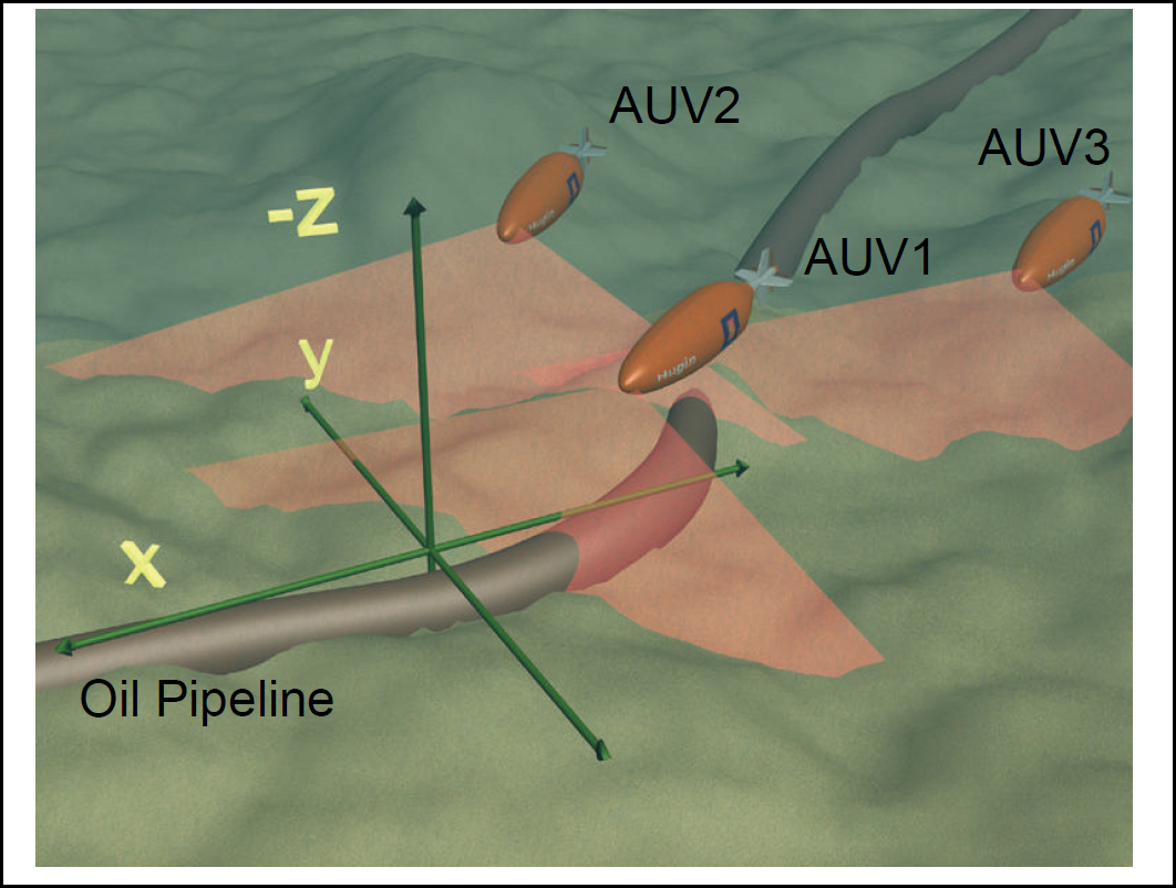
Sketch of underwater oil pipeline inspection using cooperative multiple AUVs in a formation
Besides the point stabilization and trajectory tracking, path following is one of the advanced methods for marine vehicle motion control, which requires the vehicle to reach and follow a desired spatial path without explicit temporal specifications (Lapierre, L. et al., 2003). In the scenario of underwater pipeline inspection, there are three parallel paths followed by three AUVs in 3D space, which are elevated from the seabed and offset from the underwater oil pipeline, and the speeds of vehicles along the pipeline should be the same as that determined by the end-user. Therefore, in the point of view of control design, the challenging of underwater oil pipeline inspection falls into the category of path following control. Most importantly, the vehicles are requested to keep synchronously moving along the paths to stay in a formation, to cooperatively acquire complete 3D images of the pipeline. Therefore, proper coordinated control strategy has to be adopted to accomplish the mission of pipeline inspection.
However, due to severely constrained bandwidth of underwater acoustic communication, coordinated control of multiple vehicles tackled in the field of underwater vehicles is far more difficult than the corresponding cases, including coordinated navigation of mobile robots on land (Desai, J.P. et al., 2001), formation flying control of unmanned aerial vehicles in air (Koo, T.J. et al., 2001), or attitude synchronization of statellites in spaces (Kang, W., 2002), where the high speed communication networks are easily built in these cases. That means, we have to take into account the communication constraint during coordinated control design for multiple underwater vehicles, campared with mobile, flying or space robots. The underlying requirement is that the amount of information exchanged among the underwater vehicles should be kept to a minimum.
As the bandwidth of underwater acoustic communication is severely constrained, which inhibiting a large number of data exchanges among the vehicles, one feasible strategy for coordinated control of multiple AUVs is to elect one of the vehicles as the leader and the others as followers. In this kind of leader-follower design, one significant advantage is that the only communication event required is to broadcast the necessary information of the leader to other followers. In (Encarnacao, E. & Pascoal, A., 2001), a leader-follower strategy is adopted for coordinated trajectory tracking and path following of an autonomous surface vehicle (ASV) and an AUV. However, it requires a large amount of kinematics and dynamics information to be exchanged between the leader and follower, besides compex computation of trajectory tracking controllers as a complement of path following controller. In (Lapierre, L. et. al., 2003), an important idea of decoupling the spatial assignment (predefined path) and temporal assignment (desired speed) is proposed. However, two completely identical paths in different depth are followed by an ASV and an AUV, which is not easily generanized to arbitrary parallel non-identical paths. In (Ghabcheloo, R., et. al., 2005), decentralized path following control is suggested for coordination of multiple AUVs, but it requires a large number of acoustic communicaton among vehicles for information exchange. Actually, it is very hard to build such complex underwater communication network to realize freely data exchange under contemporary acoustic communication technology, which is not the same as the counterpart cases on land, in air, or in space.
In this paper, the leader-follower strategy is adopted for coordinated path following control in terms of arbitrary parallel paths when AUVs following the actual track of underwater pipeline and acquiring 3D images. With the property of temporal-spatial speration, nonlinear control laws are explicitly derived based on Lyapunov theory. Each vehicle converges and follows the assigned path dispersing over the actual track of underwater pipeline, and speeds of followers are adapted to build the desired formation. Meanwhile, the amout of information broadcast from the leader to followers, to fulfill the control requirement, is minimized to one single variable, which is the along path length parameterizing the path (the actual track of underwater pipeline) of the leader. There are no Cartesian positions and relative speeds among vehicles requested in the coordinated control laws. Moreover, in the framework of leader-follower strategy, indeed, the communication requested among vehicles in the formation team is independent of the number of vehicles in the team, due to the broadcasting communication structure of single-source and unidirection. Therefore, the single variable and single-source communication warrant the coordinated control strategy embodied into the multi-AUV network, is able to run smoothly under the constraint of limited acoustic communication bandwidth.
The paper is organized as follows. Section 2 describes the kinematics and dynamics of an AUV. By introducing a dedicated Serret-Frenet frame, section 3 illustrates the solution to the problem of individual path following control. In section 4, the coordinated formation controller for multiple AUVs following parallel curved paths stemmed from the underwater pipeline, is proposed under rigorous Lyapunov-based design. Moreover, the control design is in the framework of leader-follower strategy, which is quite feasible under severe constraints of limited acoustic communication bandwidth. Simulation results are presented in section 5, and the conclusion and future work are drawn in section 6.
In this paper, fully actuated autonomous underwater vehicles are considered. For the under-actuated underwater vehicles, the kinematic and dynamic model are described in (Lapierre, L. & Jouvencel, B. 2008) in detail. Fig. 2 shows a fully actuated autonomous underwater vehicle in Cartesian coordinates. In order to describe the motion of the AUV, three kinds of reference frames are illustrated here.
Inertial frame {I}, which is also called as fixed reference frame or global coordinate frame in Cartesian space. Body fixed frame {B}, with origin at the center mass of the vehicle. Flow frame {W}, which is obtained from {B} by rotating it around the ZB axis through sideslip angle β in the positive direction.

Autonomous underwater vehicle: frame definitions
Let Q denote the center of mass of an AUV with 3-DOF moving in 2D plane, and let [x, y, ΨB]T be the generalized position of Q, where (x, y) are the coordinates of the origin of {B} in {I}, and ΨB is the orientation of vehicle (yaw angle). Let [u, v, r]T be the velocities of the AUV relative to {I} and expressed in {B}, where u and v are the longitudinal (surge) and transverse (sway) velocities respectively, and r is the angular speed (yaw rate). The kinematic equations of the AUV can be written as

Assuming u is never equal to zero, and | v | u. Then, the sideslip angle β can be defined as arctan(v/u). As the rotation from the body frame {B} to the flow frame {W} is denoted by sideslip angle β, the kinematic equations can then be re-written to yield
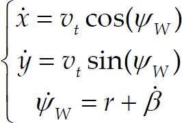
where Ψ
W
=Ψ
B
+β, and v
t
is the x
W
component of the total vehicle velocity expressed in {W}. Clearly,
Notice how the choice of a new frame simplified the first two terms in kinematic equations and brought out their similarities with those of a unicycle-type wheeled robot. Hence, we can get some indications from classic motion control design of wheeled robot (Soetanto et al., 2003) for that of underwater vehicle.
Now, consider the simplified dynamcis of a fully actuated underwater vehicle. The vehicle is equipped with longitudinal and lateral thrusters, such that the forces in surge and sway and the torque in yaw can be generated independently. Neglecting the equations in heave, roll, and pitch, the dynamics in body fixed frame can be written as (Aguiar, A.P., 2002)
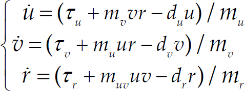
Where τ
u
, τ
u
and τ
u
denote the surge force, sway force and torque applied to the vehicle, respectively, and m
u
, m
v
, m
r
, m
uv
, d
u
, d
v
, and d
r
are vehicle parameters. With
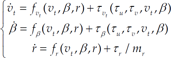
Where the transformation between (3) and (4) is non-singular and can be easily derived.
Consider in Fig. 3, where a fully actuated autonomous underwater vehicle follows a spatial path S, representing the actual track of an underwater pipeline. Let P be a arbitrary point on the path to be followed, and Q be the center of mass of the underwater vehicle. Associated with P, consider the corresponding Serret-Frenet frame {F}. The origin of the Serret-Frenet frame is P, and the tangent vector along the path to the curve is chosen as the x-direction of {F}, the principal normal vector is chosen as the y-direction of {F}. Namely, the path S is parameterized by a moving target P on the path, with the curvilinear abscissa (along path length) denoted by s.
Let (s
e
, y
e
) denote the coordinates of Q in {F}. Let the rotations from {I} to {F} and {I} to {B} be denoted by the yaw angles ΨF and ΨB, respectively. Further, let c
c
(s) denote the path curvature, and then ΨF = c
c
(s)s. Accoriding to simple geometric rules in Fig. 3, it follows that


Seret-Frenet frame and error variables
Taking derivatives and expressing the result in frame {F} yields
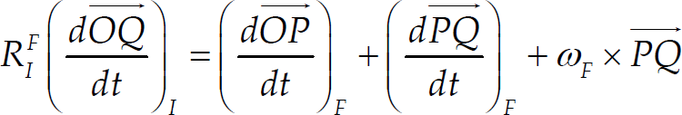
Let
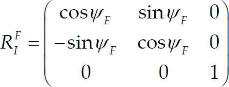
be the rotation matrix from {I} to {F}.
With the explicit relations

And

simple but tedious computations lead to the kinematic model of the AUV in the Serret-Frenet frame as

where
In this context, the Serret-Frenet frame {F} plays the role of the body axis as a “virtual target” that should be catched by the “real vehicle”. The coordinates (s e , y e ) and the angle Ψ e become the error space [y e , s e , Ψe]T, where the path following control problem is formulated and solved. However, the origin of the Serret-frenet frame {F} that moves along the path to be followed in this paper, is not attached to the closest point to the vehicle on the path, which is significant different from that in (Micaelli, A. & Samson, C., 1993). Instead, the origin of {F} is cooperatively moving on the path according to the position of the real vehicle, in order to minimize the error space. This simple but effective procedure is instrumental in lifting the stringent initial condition constraint that comes up in the work of (Micaelli, A.& Samson,C., 1993) for path following of wheeled robots and in that of (Encarnacao, P.& Pasoal, A., 2001) for marine vehicles. Because of the singularity at ye=1/c c , the control laws derived require that the initial position of Q be resrited in a ‘tube’ around the path, the radius of which must be less than 1/max(c c ), where max(c c ) denotes the maximum curvature of the path. Clearly, this constraint is very conservative and not rational for practical sea trials as AUVs might try to follow and inspect an underwater pipeline from a litter bit far away initial positions.
By indicating s1 not necessarily equal to zero, a virtual target not coinciding with the projection of the vehicle on the path is created, which introducing an extra degree of freedom for controller design. By cooperatively specifying how fast the newly defined target moves, the occurrence of the singularity is removed. Therefore, the AUV is able to follow and converge to the predefined path from an arbitray initial position in the theoretical point of view. Notice how the kinematics in (5) are driven by actual input v t (total vehicle speed) and r (angular speed), and the derivative of s (the speed of virtual target moving on the path) which plays the role of an extra control input.
With the above notation, the problem of pipeline path following for single AUV, can be formulated as below:
Given an assigned path of the underwater pipeline to be followed by a fully actuated AUV, and given a desired speed profile vd(t) > vmin > 0 for the vehicle speed v
t
, derive kinematic control laws to drive y
e
, s
e
, Ψ
e
and v
t
−v
d
asymptotically to zero.
From the problem formulation, the possible solution can be divided into two tasks: a geometric task, where the AUV is required to converge to the desired pipeline path with error space equal to zero; a speed task, where a desired speed assignment along the path is pursued.
In order to converge to the desired path, the most important thing is to steer the vehicle in the right heading to approach the objective, and desired speed is of second interest. As in (Soetanto, D. et al., 2003), define the approach angle

Where 0 < θa < pi/2 and kδ > 0. The approach angle δ satisfying y e v t sin δ ⩽ 0, is instrumental in shaping transient maneuvers during the path approaching phase. In fact, the approach angle is the heading reference for maneuvering the vehicle. Classic LOS law for heading reference is popularly applied in marine vehicles (Fossen. T., 1994) and (Fossen. T. et.al, 2004). This kind of method enlightens us on designing another heading reference for AUVs. This physically meaningful approach angle, based on the guidance of LOS angle with helmsman like behavior embodied, is proposed in (Xiang, X.B. et al., 2009). Moreover, the new approach angle is also instrumental in nonlinear controller design to sharpen the performance of convergence.
Consider the following Lyapunov function candidate

Recalling the AUV kinematics model in Serret-Frenet frame (5), the derivative of V1 is

It is straightforward to show that the choice

where k1 and k2 are positive gains, lead to

With the approaching angle designed in (6), y
e
v
t
sin δ < 0. Therefore,
On the other hand, as

the yaw rate (one of the control input) can be written as
In order to achieve desired speed, we select Lyapunov function candidate

It is trivial to choose the speed control law

where k3 > 0.
With (9), Vv is negative definite outside the origin. Assuming v d (t) > v min > 0, the vehicle speed v t converges to desired speed vd with performance of global uniform asymptotic stable.
Remark
In the overall control loop, the kinematic controller actually acts as a reference subsystem, giving the desired signals for the control subsystem based on the dynamics level. Using backstepping techniques (Krstic, M. et al., 1995), the control law in kinematic level can be extended to deal with vehicle dynamics. Due to space limitations, we will focus on kinematic level in this paper. However, equations in (4) will be the base for backstepping control design in dynamic stage. Thus we refer the reader to (Lapierre, L. & Jouvencel, B. 2008) and (Xiang, X.B. et al., 2009), and references therein, for a detailed discussion of controller design in dynamics.
In this section, the characteristic of individual path following control is analyzed firstly. Based on this elegant characteristic, control design of coordinated path following is proposed, with the parallel paths formulation for underwater pipeline inspection.
Characteristic of individual pipeline following control
In the control design of (9), it indicates that controlling speed v t is thoroughly decoupled with geometric control behavior in (7). That means, the geometric control behavior drives the vehicle onto the path with error space [y e , s e , Ψe]T equal to zero (i.e. spatial assignment in path following design) no matter how the speed controller works, so that the spatial assignment is throughly separated from speed convergence (i.e. temporal assignment in path following design).
This important characteristic of spatial-temporal decoupling in individual path following control, endows the coordinated path following controller with a dedicated ability of speed adaptation among multiple vehicles, without degrading the performance of individual vehicle's convergence to the path. At the same time, this outstanding feature enables the controller to coordinate heterogenous multi-vehicle system with different dynamics, as the speed adaptation that is the essence of coordinated control, is independent with dynamics.
Therefore, the feasible strategy for coordinated pipeline path following to build a formation, is that
Elect one vehicle as a leader and other vehicles as followers. Both the leader and the followers recruit their own path following control laws to track the assigned paths, and then, based on the generalized along-path length s
1
broadcast from the leader, adjust the desired speed of follower vehicles, bring all generalized along-path length s
i
(i = 1, 2, …, n), to be equal for in-line formation or fulfill some geometric conditions for specific formation, such as triangle formation.
With the above analysis, the problem of path following for single AUV can be formulated as below:
Given n parallel paths to be followed by n AUVs, and given a desired speed profile vd
1
(t) > v
min
> 0 for the speed v1 of the leader vehicle, derive feedback control laws to drive sei, yei, Ψ
ei
, v
i
−v
d1
(i=1,2,…,n), and the error of generalized along-path distance Δs1j (j=2,…,n) defined in the geometric formation, asymptotically to zero.
Formulation of parallel pipeline paths
In (Borhaug, E. & Pettersen, K.Y., 2007), assigned paths to be followed by multiple vehicles are straight lines, and in (Lapierre, L. et. al., 2003), there are identical paths followed in different depth in three dimension. However, in the case of pipeline inspection, the envisioned paths formulation is, one AUV as a leader exactly follow the path above the actual track of underwater pipeline, other AUVs will follow the parallel paths related to the leader, so that the 3D images of the whole pipeline can be capatured. That means, in general not straight lines or identical paths, but parallel curved paths have to be formulated (Xiang X.B., et al., 2009), which are compatible with real situation of underwater pipeline inspection.
For explicity, an in-line formation with n vehicles while following a set of parallel curved paths, is depicted in Fig. 4. Parallel paths are created by shifted vectors di related to the baseline of the actual track of the pipeline. The individual path for ith vehicle (i=2, 3,…,n) with respect to the path of the first vehicle (leader), is formulated as

where u is the path parameters, and RIB is a rotation matrix from the moving body frame B along the path to the inertial frame I.
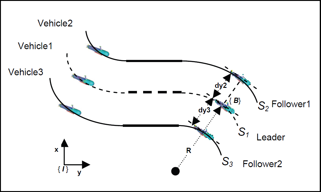
Illustration of parallel pipeline paths
For one underwater vehicle moving on the 2D plane, the desired path which the leader is following, is then given by s(μ) = [x(μ), y(μ), θ(μ)]T,where μ is a path variable. The tangent vector along the path in the (x, y) directions is chosen as the x axis of the moving body frame {B}. The angle of the tangent vector in the inertial frame {I} gives the heading θ(μ) = arctan(y(μ)/x(μ)).
Therefore, the rotation matrix for the parallel paths is given by

In order to simplify the control design, one vehicle is elected as a leader, with the formation shifted vector d1 = [0, 0, 0]T. It means that the leader coincides with the AUV1, and other vehicles will be followers with shifted vector di = [0, dyi, 0]T, i = 2, 3, …, n.
In the case of in-line formation for parallel paths as depicted in Fig. 4, there is always a relationship between the along-path position of the virtual target of the leader s1, and the desired along-path position of the virtual target of the follower s
d
2. That is
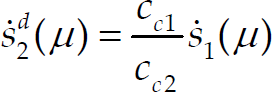
Since cci = 1/Ri, where Ri is the radii of the tangent circle (i.e. the circle of curvature which is tangent to the curve) at one point of the path. According to the path formulation, there is R2 = R1+dy2, such that

Substitute (11) with (12), and then

Therefore,
Remark
In the case of other specific formations, only the geometric specification of the formation will be superposed in (13) to formulate the relationship between s1 and s d 2.
Leader Controller
In the case of the leader, a path following controller is easily obtained by recruiting laws of (7) and (9). That is,

where v1 is the actual speed of the leader, vd1 is desired speed profile of the leader, and the derivative of vd1 is normally equal to zero.
Obviously, the first two terms of control law in (14) contribute to geometric assignment, and the third one contributes to speed assignment.
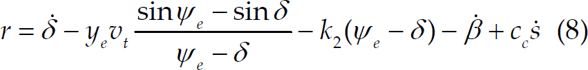
The follower recruits similar path following control laws to those recruited by the leader.
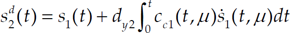
The only difference between the controller of the leader and that of the follower is that, the follower's forward speed v2 must be adapted to reduce the relative generalized along-path distance between the two vehicles to zero. A solution proposed to speed adaption is

Where
Straightforward computations show that the derivative of the follower's speed is

Where kv > 0 is a slack variable to impose restrictions on how much the follower's speed is allowed to catch up the leader.
There is one thing highlighted in the controller design, that only the generalized along-path length of the leader
In the case of the follower (AUV3), the follower recruits similar path following control laws and speed adaptation control law to those recruited by the second follower (AUV2). The only difference between the controller of the follower AUV2 and that of the AUV3 is, the error of along path distance (Δs13) between the leader (AUV1) and the follower (AUV3) is different with Δs12 in mathematical formulation.
As the follower AUV3 has the desired path on the left side of the leader's path, the error of along path distance is as follows

Such that the speed control design is different.

If there are more than two followers, other followers will recruit similar control laws with the second follower (AUV2) and the third follower (AUV3). The mathematic representation of Δs1n heavily depends on the position of the nth follower, which is on the right or left side of the leader's path. Generaly speaking, in the case of in-line formation for parallel paths, the ith follower's path is with a shifted vector di = [0, dyn, 0]T based on the leader's path. And then, the generalized speed control design for the nth follower, is as follows

With control laws proposed here, both the leader and the follower asymptotically converge to the paths, and their relative along-path distance is guaranteed in terms of geometric constraints of the specific formation, such as the triangle formation in this paper.
A formal proof of the nonlinear controller for coordinated pipeline following in a formation proposed here, heavily relies on Lyapunov-based design and Lasalle's invariance principle, which is similar to the method introduced in (Lapierre, L. et al., 2006) for a single vehicle, and in (Xiang, X.B., et al., 2009) for multiple vehicles. The indication of proof for coordinated formation control on parallel pipeline paths following, is given as follows.
Proposition
Consider the kinematic models (5) of n AUVs described in in Frenet-Serret frame. Let n parallel paths be generated through the rotation matrix in (10). Assume that v d1 > v min > 0 is the desired speed profile for the leader vehicle. The feedback control laws in (14) for the leader, (15) and (18) for the follower, drive sei, yei, Ψ, v i −v d1 (i=1,2,…,n), and the error of generalized along-path distance Δs1j (j=2,…,n) defined in the geometric formation, asymptotically to zero.
Proof
The coordinated controller design for path following in an in-line formation, is derived in four steps.
Given individual path following control law in (7), or the first two parts in (14)/(15) for each AUV, the multiple AUV systems will uniformally globally exponentially reach the largest invariant set
Given individual path following control law in (9), or the last part in (14)/(15) for each AUV, the multi-AUV system will uniformally globally exponentially reach the largest invariant set
Under these two invariant sets, let's select the Lyapunov candidate function we use Lasalle's invariance principle (Khalil, H. K., 2002) to concatenate the two previous convergence properties. The first and second step of the proof showed that every solution starting in {Ω | (x
i
, y
i
) ∈ R2} where (x
i
, y
i
) is the initial position of vehicle, asymptotically converges to the invariant {Ω
path
∩ Ω
v
}. The third step showed that the largest invariant set of {Ω
path
∩ Ω
v
}, is the invariant manifold M. Therefore, every bounded solution starting in R2 converges to invariant manifold M which indeed is s1' =s2 = … = sn. Hence, all AUVs will be coordinated to follow the assigned paths in an in-line formation.


Remark
In the case of speical formation other than in-line formation, such as triangle formation in Fig. 1, the geometric specification has to be taken into account. Assuming AUV1 is the leader, there is
This section illustrates the performance of coordinated path following controllers for three AUVs inspecting underwater pipeline, based on leader-follower strategy proposed in this paper. The leader and the followers are required to keep a triangle formation with l0 = 5m, and the leader flies above the pipeline with 5m depth. The leader coincided with the AUV1 in Fig. 1, such that the shifted vector of corresponding pipeline path is d1 = [0m, 0m, 0m]T. Both AUV2 and AUV3 are followers, whose parallel paths are with shifted vector d2 = [0m, 7m, 0m]T and d3 = [0m, −7m, 0m]T according to the 2D projection of the leader's path (the actual track of pipeline) respectively. The initial positions of the leader and the followers are (30m,−30m,5m), (20m,−30m,0m) and (40m,−30m,0m) respectively. The initial speeds of the leader and the followers are 0.1m/s, and the desired speed vd1 is set to 1m/s. The control parameters are given as: k1=0.5, k2=0.1, k3=0.2, kv=3.0.
As depicted in Fig. 5, the underwater pipeline and AUVs paths are illustrated in 3D. The projected 2D graph is showed in Fig. 6, both the leader, left and right followers converge to the assigned paths, and keep the triangle formation.

Underwater pipeline and AUVs paths in 3D

Leader/Followers paths projected in 2D with a triangle formation
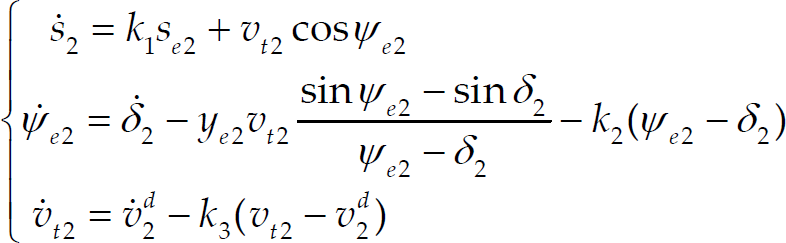
In Fig. 7, the error spaces of three vehicles with respect to the paths are driven to zero. The forward speed adaptions of the followers are illustrated in Fig. 8, and the angular speeds of the followers are the same as that of the leader when the triangle formation is built. Notice that the actual forward speed converges to u d = 1 m/s. In Fig. 9, the errors of generalized along-path distance Δs1j (j=2,3) between the leader and followers are decaying to 0, where the geometric constraints of l0 is already incorporated.

The relative distances of vehicles/virtual targets
Linear and angular speeds
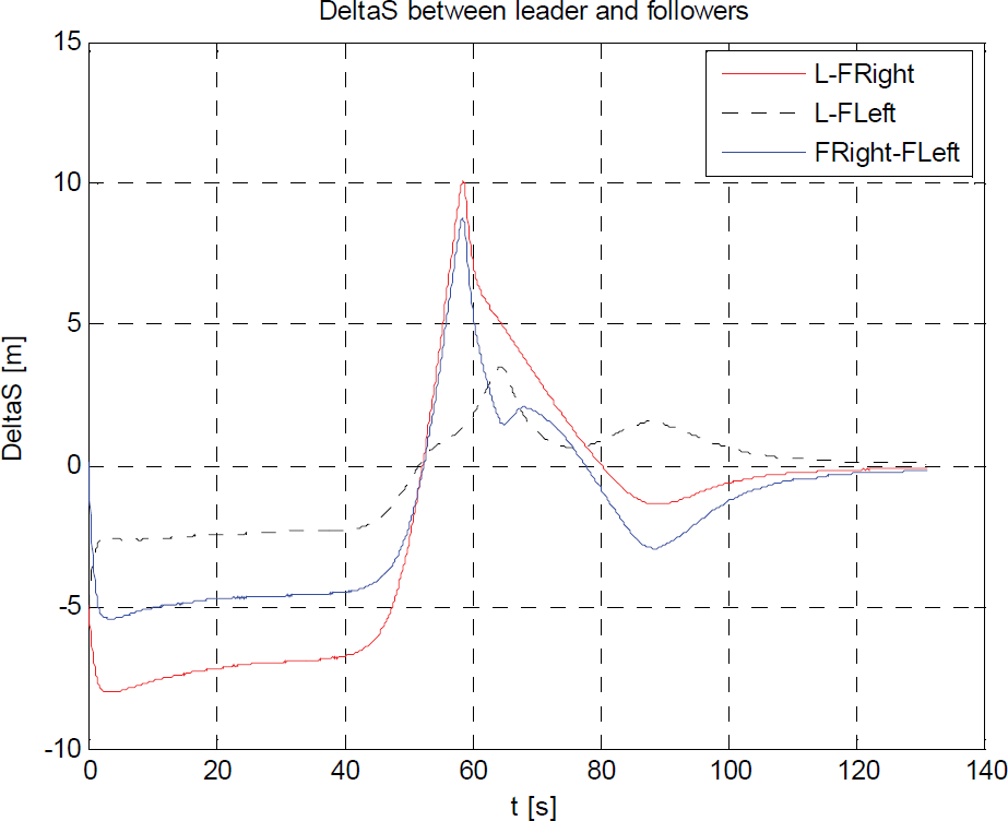
The evoluation of the relative distance of Leader/Followers
This paper addressed the problem of coordinated parallel path following control of AUVs, based on the leader-follower strategy while keeping the desired triangle formation to inspect underwater pipeline. Both the leader and the followers adopt similar path following control laws. However, the leader was independently travelling along the assigned path at a desired speed assignment, and the followers were then adapting its own speed according to the information of a generalized along path distance of the leader, and tried to catch up with it while minimizing the errors. The single communication variable broadcast from the leader warranted that, the coordinated control strategy is quite feasible under severe constraints of limited acoustic communicaiton bandwidth. Simulation results for the triangle formation illustrated the efficacy of the solution proposed in the paper.
Further work will address the problem where multiple vehicles are required to follow spatial paths with collision-free properties in switching formation topology, and obstacle-avoidance properties in complex underwater environments. Time delays and packet loss inside the acoustic communication network are of interest to be integrated into coordinated path following. The formation control of multiple vehicles in the presence of ocean currents will also be taken into account in the future work.
Footnotes
7. Acknowlegements
This research work was partially supported by the European FP6 FreeSubNet project (![]() ) under the grant 036186, and the Key Laboratory of Education Ministry for Image Processing and Intelligent Control, Huazhong (Central China) University of Science and Technology under the grant 200804. Xianbo Xiang acknowledges the European Marie Curie Fellowship.
) under the grant 036186, and the Key Laboratory of Education Ministry for Image Processing and Intelligent Control, Huazhong (Central China) University of Science and Technology under the grant 200804. Xianbo Xiang acknowledges the European Marie Curie Fellowship.