
Abstract
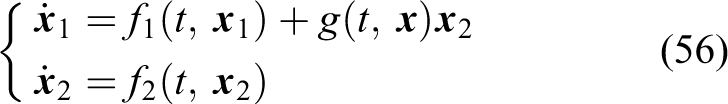
This article presents a nonlinear adaptive line-of-sight path following controller for underactuated autonomous underwater vehicles in the presence of ocean currents. Firstly, a new nonsingular path following error kinematic model in the Serret–Frenet frame is developed, where a nominal course angle error is introduced to significantly simplify the guidance law design. Secondly, an adaptive line-of-sight guidance law with the introduction of the current observer is proposed to make the vehicle produce a variable sideslip angle to compensate for the drift force for any parametric curved-path path following. Benefit from the global κ-exponential convergence property of the designed current observer, the actual course angle error can be eliminated indirectly. Then, dynamic controller built on Lyapunov theory and backstepping technique guarantee the uniform global exponential stability of the yaw and relative surge velocity. In the end, stability analysis shows that the global κ-exponential stability is achieved for the closed-loop system. Simulation results demonstrate the effectiveness of the proposed control scheme.
Keywords
Introduction
Unmanned marine vehicles are particularly useful in a variety of activities, such as, oil exploration, undersea cables inspection, environmental monitoring, and seabed mapping. 1 –4 Marine vehicles involved in these activities usually execute path following operations. In particular, autonomous underwater vehicles (AUVs) have a major advantage than unmanned surface vehicles (USVs) and remotely operated vehicles (ROVs), when the task is performed in deep waters. However, most AUVs are underactuated and the main environment disturbance ocean current is inevitable, precise path following is challenged.
In path following control scenario, a vehicle is required to follow a predefined path without temporal constraint. 5 Specifically, the control objective can be described as a force the vehicle to pursue a virtual target point along the path. Since the depth-pitch control of AUVs is usually decoupled from the horizontal plane, most path following control is limited on two-dimensional (2-D) path. In this case, it has something in common with USVs and surface vessels. In recent two decades, various research results have been presented focused on the virtual target-based path following control of AUVs and other marine vehicles, for instance. 5 –9 Encarnação et al. 5 addressed the path following control of an autonomous marine craft in the Serret–Frenet frame and designed a local path following controller. Using Lyapunov direct method and backstepping technique, a nonsingular path following control law for AUVs was proposed by Lapierre et al. 6 Considering both the fully-actuated and under-actuated configurations, a novel nonlinear path following controller for fully-actuated/under-actuated AUV was presented by Xiang et al. 7 Lekkas et al. 8 investigated both the path planning problem and the guidance problem for marine vehicles by introducing a variation of the cubic Hermite spline interpolation (CHSI) technique and a new integral line of sight (ILOS) algorithm. Using the Nussbaum gain method, a path following controller for underactuated underwater vehicle with inputs constraint was developed by Qi. 9 It is noted that if the virtual target on the path is chosen to be the nearest reference point, the initial cross-track error should be restricted to be smaller than the smallest radius of the path curvature. This singular problem existed in the literatures. 5,8 A better solution to relax the initial condition constraints of path following is to select the reference point to be an arbitrary point on the path which will result in the addition of the along-track error. 6,7,9
Guidance law is of critical importance that determines the overall performance of the controller during the path following. The LOS method is an effective and popular way to design the guidance law. 10 –16 It has proven to be uniform global asymptotic stability (UGAS) and uniform local exponential stability (ULES). 10 Note that the original LOS guidance law ignored the environmental disturbances and is actually a kind of proportional guidance method. Meanwhile, this LOS guidance law is mainly used for straight line path following. To handle the constant ocean current disturbance in straight line path following, an ILOS guidance was first proposed by Børhaug et al. 11 and improved by Caharija et al. 12 Børhaug et al. 11 described the dynamics of the marine vehicle by both the absolute velocities and the relative velocities. This makes the controller complex and the system stability weakened. This drawback was removed by Caharija et al., 12 using the relative velocities of the vehicle. Later, the ILOS was extended to three-dimensional straight line path following for AUVs 13 and for underwater snake robots. 14 However, this ILOS guidance law was not suitable for curved-path path following since the desired heading angle will not change when the cross-track error is eliminated. Therefore, it is necessary to modify the LOS guidance law that applies to curved path. Recently, an adaptive LOS (ALOS) guidance principle was proposed by Fossen et al. 15 However, the sideslip angle to be estimated was assumed to be small and constant, and the guidance law was mainly used for Dubins paths. Under the assumption that the path-tangential angle of the desired path varies slowly, an improved adaptive ILOS guidance law was developed by Zheng et al. 16
Environmental disturbances induced by ocean currents, wind, and waves have critical impact on the motion of marine vehicles. 17 In particular, ocean current is the main ingredient of the disturbances for underwater vehicles. So far, most ocean current research results on marine vehicles are under the assumption that the current is irrotational and constant. 5,11 –14,18 Under this assumption, the model of the marine vehicle can be described by the relative velocities, which makes the controller design convenient that can be seen by reviewing Caharija et al. 12 If the ocean current is unknown, current observers are useful in controller design, such as, path following, way-point tracking, and position tracking control. 5,19 –21 These current observers were designed based on the kinematic equations of the vehicle, and the position estimation can be obtained simultaneously. In addition to these observers, the ILOS guidance law also provided a current estimation method by using the steady-state integral term and the relevant velocities. 12 Instead of estimating the current directly, Fossen et al. 15 proposed an adaptation law to estimate the vehicle sideslip angle to compensate for the drift force caused by ocean currents. This method adopted absolute velocities and was mainly used for marine surface vehicles.
Motivated by the above considerations, this article addresses the precision improvement of 2-D curved-path path following control for underactuated AUVs exposed to ocean currents. The current is assumed to be irrotational, constant, and unknown. Considering the current disturbance, a new path following error kinematic model with an amendment to the definition of the course angle error in Serret–Frenet frame is first proposed. Based on it, we propose a new ALOS guidance law which comprises a current estimator. With this guidance law, the vehicle can sideslip to compensate for the drift force. Since the position track errors and the current estimation errors are proven global κ-exponentially converge to zero. The actual course angle error are shown to be eliminated indirectly. Using Lyapunov direct method and backstepping technique, the yaw and relative surge velocity can be controlled simultaneously. Stability analysis shows that the closed-loop system has the stronger stability property of global κ-exponential stability.
To this end, this article makes the following contributions: (1) The new path following error kinematic model developed in this article takes into account the current influence, which is the extension of the model presented by Lapierre et al. 6 (2) The nominal course angle error introduced in this article significantly simplify the guidance law design. Meanwhile, the proposed adaptive LOS guidance law can provide AUV with a variable sideslip angle and an accurate current estimation during the path following. (3) The drift angle in this article is not assumed to be small or constant, the guidance law is suitable for curved path with arbitrary curvature not just straight line or circular paths. (4) In the end, this article presents an explicit analysis of the steady state of the AUV in curved-path path following and proves the validity of the introduction of the nominal course angle error.
The rest of this article is organized as follows: “Problem formulation” section presents the path following error kinematics and the control objective. “The path following control system” section proposes an ALOS guidance law and designs the dynamic controller of the vehicle. Meanwhile, the stability analysis of the control system is given. In the section “Simulation results and discussion,” simulation results are provided to illustrate the proposed control method. “Conclusion” section concludes this article.
Problem formulation
In this section, considering the current disturbance, the kinematic and dynamic equations of the underactuated AUV are described in relative velocity form. Then, a new path following error kinematic model in the Serret–Frenet frame is presented. In the end, the control objective is formulated.
Model of the AUV
To study the AUV motion on horizontal plane, the motions of heave, pitch, and roll are neglected. Let the vector

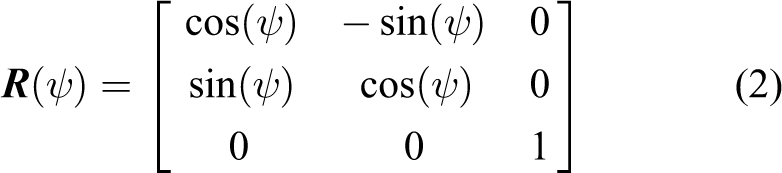
where the matrix
Define the ocean current velocity vector as

where
Assumption 1
The current is constant, irrotational and its speed is bounded by a constant Vcmax that is
Assumption 2
The magnitude of the relative velocity of the AUV is positive, bounded and larger than that of the current velocity such that
Remark 1
When in normal operation, the AUV moves faster than the current. Furthermore, for most AUVs, their speeds are designed to reach much more than 5 m/s and the current speeds are usually less than 1 m/s. Therefore, Assumption 2 is easy to meet for most AUVs. Similar assumptions for other marine vehicles can be seen in the literatures Lekkas et al. 23 and Fossen et al. 24
Then, the kinematics of the vehicle expressed by the relative velocities and the current velocities in vector and component forms are


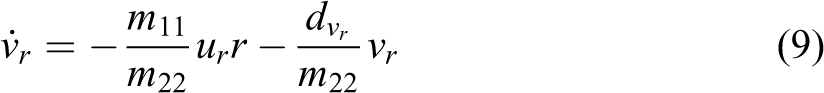
To simplify the dynamic model of the AUV, the vehicle is assumed to have three planes of symmetry and a neutrally buoyant. The damping terms higher than two order are not considered. Then, according to Fossen, 22 the dynamic equations of an AUV in relative velocity form are

where

with


Path following error coordinates
In order to describe the path following control problem, a local reference frame {f} associated with P is built and christened the Serret–Frenet frame, 6 as shown in Figure 1. The point P is a free reference point or called the ‘virtual target’ on the predefined planar path S to be followed. The path S can be described by the signed curvilinear abscissa s of P or the path variable ϖ. The position of the vehicle’s center of mass Q can be defined as xe and ye in {f}, where xe is the along-track error and ye is the cross-track error.

The path following error coordinates.
Let the vector

Where
Assumption 3
The curvature of the path and the velocity of the reference point on the path to be followed all have constant upper bounds such that
Notice that, in previous works,
6,7,9
the error kinematic equations were built regardless of the ocean current and the course angle error
For a given vehicle state

By differentiating equation (12) with respect to time yields the error kinematics


Where,

Substituting equation (5) and equations (11) to (12) into equation (13) gives

Since

The control objective
Consider an underactuated AUV given by equations (4) and (6). Let the path be described as a planar geometric curve

The path following control system
In this section, the guidance-based path following control system is presented. Consider the current is unknown in advance, an ALOS guidance law with a current observer is first proposed. It is suitable for curved path with arbitrary reasonable curvature. The dynamic controller is designed using backstepping technique. In the end, stability analysis shows that the equilibrium point of the path following error system is global κ-exponential stable.
The ALOS guidance law
In the original LOS guidance law, the heading angle of the vehicle is designed to approach a LOS angle, 10 and it is applicable for straight line path following with no external disturbance. For the integral LOS guidance scheme, 11 the heading angle is modified to approach a non-zero LOS angle to compensate for the drift force. However, the integral term will be unchanged when the cross-track error is eliminated, thus it will result in a constant steady LOS angle. This is not reasonable in curved-path path following since the desired heading angle of the vehicle will be variable for different tangent direction angle of the path. Therefore, the desired heading angle should be further modified to adapt to curved path. Considering the AUV model (4), (6), and the path following error kinematics (16) are described in relative velocity form, the desired heading angle ψd can be designed as

Notice that βr is not equal to β when the vehicle is moving on a curved path in current environment, as illustrated in detail in Figure 2. Thus, we cannot hope

The steady state of the AUV in curved-path path following exposed to ocean current. AUV: autonomous underwater vehicle.
Then, the next step is to design the guidance angle in equation (18). Since the ocean current is considered unknown, we define

where k1 > 0 is a design parameter, Δ > 0 is the look-ahead distance, and μ is the integral term that creates a variable sideslip angle. In addition, using the inverse rig function arcsin(⋅) instead of arctan(⋅) is convenient for stability analysis. To estimate the unknown ocean current, the adaptive update law for the current parameters estimation can be designed as

where γc > 0 is the design parameter.
Remark 2
Combining the current estimation update law (20) and the ALOS guidance law (19), it can be seen that the proposed guidance law is available online in practice since the position track errors xe and ye are measurable and the path tangent direction angle αp is known.
The kinematic controller
As mentioned above, the heading control objective is to stabilize the nominal course angle error


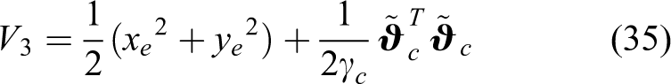
where k2 and k3 are positive control gains. Choose the Lyapunov function candidate (LFC)

for some
To acquire a causal form rd, we make some algebraic computations on

Then, the virtual control rd can be calculated as

Notice that the hydrodynamic parameters
Remark 3
To derive the guidance law and kinematic controller distinctly, we assume r = rd and ur = urd on the kinematic level. While, the required surge control τu and yaw control τr will be designed from the dynamic equations in the following subsection.
The dynamic controller
The guidance-based path following control scheme treats the kinematic controller as the reference signal to the dynamic control subsystem. While, the errors between the desired values and the actual control outputs can be eliminated on the dynamic level. Using the backstepping technique, the dynamic controller can be designed as

where k4 and k5 are arbitrary positive parameters. Define the error variables as

and choose the LFC as

Consider the dynamic equations (8) and (10), the virtual yaw rate control equation (22) and the dynamic controller (26), it follows that
With the similar analysis method of equation (23), we can conclude that the origin
Notice that

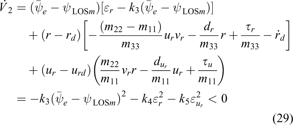
Combining the dynamic control law (26) and the dynamic equations (8) to (10), we have
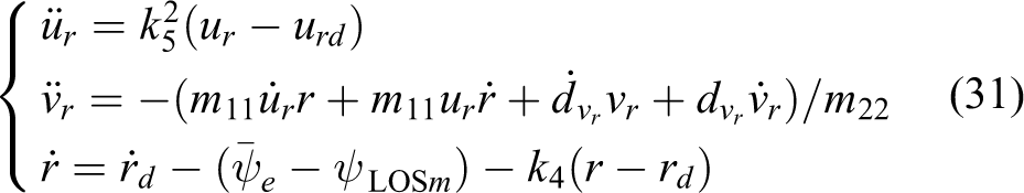
Considering equations (22), (30), and (31), we have

Where

Then, the dynamic controller can be replaced by

Stability analysis of the closed-loop system
Consider the position and the current estimation errors, we define the following LFC
From equation (16) it follows that

Since the virtual yaw rate control renders the origin

Since

Meanwhile, the error system in terms of xe, ye, and

According to the standard Lyapunov arguments, the origin
Theorem 1
For a system in the form of

where
Assumption 1
Define

Furthermore, for each compact set

for all
Assumption 1
The function
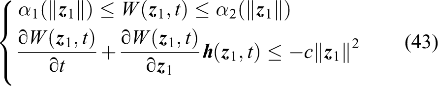
where α1 and α2 are class-k∞ functions and c > 0 is a strictly positive real number. Further, the system is ULES if
In order to analyze the stability of equation (39), we rewrite it in the following form


Denote

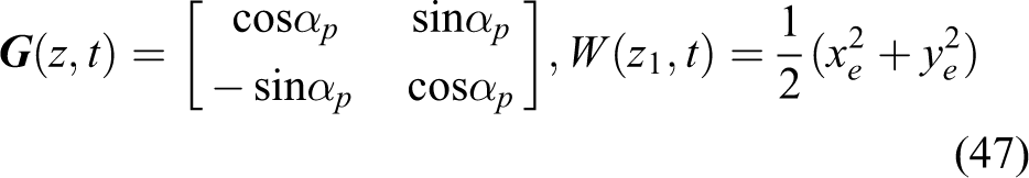
Consider assumption 2 and assumption 3, we have that
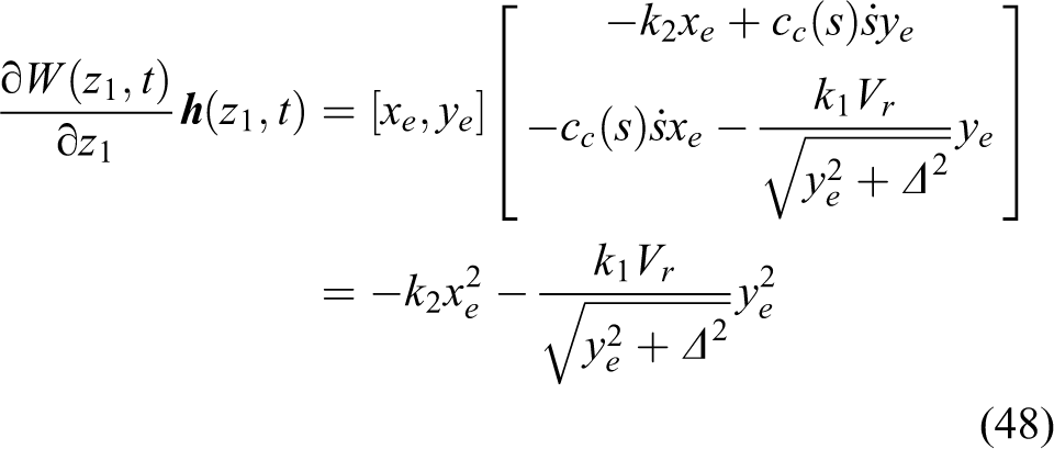
which implies that assumption A2 is also satisfied. Therefore, the system equations (44) and (45) is UGAS. In addition, if we choose
Moreover, under the above ALOS guidance law and kinematic controller, the actual course angle error ψe is indirectly eliminated which is proven in theorem 2.
Theorem 2
Consider an AUV following an arbitrary curved path in the presence of unknown constant ocean current. Assume that the nominal course angle error
Proof
If the AUV moves in current environment, the velocity vectors

and their geometrical relations are described in Figure 2. Decomposing

therefore

Consider the ALOS guidance law (19), when the AUV reaches the steady state, that is,

Substituting equation (51) into (52) and replacing

Utilizing sinusoidal function for both sides of the above equation, and thus

According to assumption 2, we have

which means that
To analyze the stability of the closed-loop system, we define the error vector of the system as
where the interconnection term
Simulation results and discussion
In this section, numerical simulation results are given to illustrate the performance of the proposed control law and the exponential convergence property of the control system is demonstrated. The considered AUV model was given by Pettersen et al. 25 In straight line path following, it shows a better convergence performance compared with the ILOS control method. 12 For curved-path path following, the AUV is assigned to follow a parametric curved path where the universal applicability and the improvement of precision characteristics are presented.
Straight line path following
The control objective is to make the AUV follow a straight line path parametrized as

Straight line path following comparison between the ILOS and ALOS approaches: position, steady-state heading angle, and heading angle. ILOS: integral line of sight; ALOS: adaptive line of sight.

Straight line path following comparison between the ILOS and ALOS approaches: position track errors, current estimations and control inputs. ILOS: integral line of sight; ALOS: adaptive line of sight.
From Figure 3(a) and 4(b), one can see that the ALOS controller has a less overshoot of the cross-track error ye compared with the ILOS method. Since the ALOS controller solved the singularity problem by using the non-nearest reference point strategy, the along-track error xe is extra as seen in Figure 4(a) and has a smooth convergence performance. Figure 3(b) shows that the heading angles of the two controllers all achieve the steady-state value
Curved-path path following
The curved path is defined in Cartesian coordinates and parametrized in polynomial form, that is
where the path parameters are shown in Table 1.
Parameters of the curved path.

The desired relative surge velocity is also chosen as

Curved-path path following: position, ALOS angle, nominal course angle error, actual course angle error and heading angle. ALOS: adaptive line of sight.
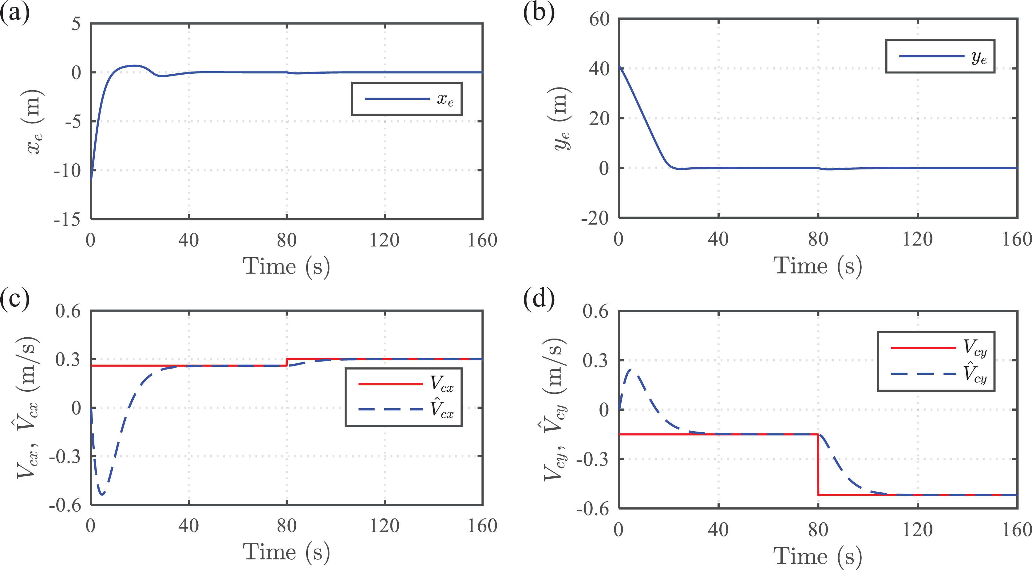
Curved-path path following: position track errors and current estimations.

Curved-path path following: relative surge velocity track error, drift angle, relative velocity drift angle and control inputs.
From the “red triangular AUV” with heading angle as shown in Figure 5(a), one can intuitively see that the AUV follows the desired curved path perfectly. The position tracking error xe, ye all converge to zero and the relative surge velocity ur approaches to the desired value urd in the end. After time t = 80 s, the current force increased and the vehicle deviates slightly from the given path and then returns to the desired position after a short time. Note that although the proposed ALOS guidance law aims to achieve
Conclusion
An ALOS path following control strategy of underactuated AUVs for current estimation and compensation of the sideslip angle has been presented. The ALOS guidance law is derived based on a new path following error kinematic model with the consideration of the current disturbance. Since the virtual target point is not the nearest reference point, the singularity problem in curved-path path following is resolved. Meanwhile, the drift angle in this article is not assumed to be too small or constant, the proposed path following control strategy is suitable for curved path with arbitrary reasonable curvature, not just straight line and circular paths. Although the proposed ALOS guidance law aims to achieve the convergence of nominal course angle error to the modified LOS angle, the global κ-exponential stability of the position and current estimation error system guarantees that the actual course angle error eliminated indirectly. Lyapunov direct method and backstepping technique are used to design the yaw and the relative surge velocity controllers. Stability analysis shows that the whole control system has the stronger stability property of global κ-exponential stability.
Simulations validate the effectiveness of the proposed control method. Moreover, in straight line path following case, it shows a better tracking performance compared with the previous ILOS guidance law. During curved-path path following scenario, the ALOS guidance law provides a variable sideslip angle to adapt to the currents and path curvature changes. Furthermore, although the proposed control strategy is designed for constant currents, it is able to respond effectively to the step change currents.
Footnotes
Declaration of conflicting interests
The author(s) declared no potential conflicts of interest with respect to the research, authorship, and/or publication of this article.
Funding
The author(s) disclosed receipt of the following financial support for the research, authorship and/or publication of this article: This work was supported by the National Science and Technology Major Project of China (No. 2015ZX01041101) and the National Natural Science Foundation of China (No. 51509057, 51709214).