
Abstract
Landing control is one of the important issues for biped walking robot, because robots are expected to walk on not only known flat surfaces but also unknown and uneven terrain for working at various fields. This paper presents a new controller design for a robotic foot to land on unknown terrain. The robotic foot considered in this study equips springs to reduce the impact force at the foot landing. There are two objectives in the landing control; achieving the desired ground reaction force and positioning the foot on unknown terrain. To achieve these two objectives simultaneously by adjusting the foot position, we propose a PI force controller with a desired foot position, which guarantees the robust stability of control system with respect to terrain variance, and exact positioning of the foot to unknown terrain. Simulation results using the Open Dynamics Engine demonstrate the effectiveness of the proposed controller.
Introduction
Biped walking has high ability to adapt to rough terrain, and enables to use the existing infrastructure efficiently. Thus, biped walking robots are expected to assist human beings in various fields. Although they have been widely studied (Hirai, K., et al., 1998) (Kaneko, K., et al., 2004), efficient biped walking on rough terrain has not been realized yet.
To achieve the biped walking on rough terrain, the following functions need to be realized. 1) Stabilization of contact states between foot and ground. 2) Landing to the unknown terrain. The conventional foot with flat surface can have enough area of support polygon, which is a convex polygon of minimum area including all contact points, when only flat terrain is considered. However, because the contact states often becomes one point-contact or line-contact on rough terrain, support polygon turns out to be small and robot falls down easily (Goswami, A., 1999) (Vukobratović, M. & Stepanenko, J., 1972). In addition, since it is difficult to recognize three-dimensional terrain accurately, the posture of the robot becomes unstable easily due to difference between predicted and actual ground.
In order to realize the first function, it has been proposed to install a rubber at the bottom of feet. However, it seems not effective for rough terrain. Hashimoto et al. developed four point-contact type foot with actuators, and attempted the stabilization of contact state by adapting a foot orientation to irregularity of the ground (Hashimoto, K., et al., 2007). Although it can adapt to rough terrain semi-actively, those actuators increase the weight of robot and decrease the energy efficiency. Furthermore, it cannot suppress the impact force at the foot landing.
In order to realize the second function, Hashimoto et al. (Hashimoto, K., et al., 2005, 2007), Nakano et al. (Nakano, E., et al., 2004) and Nakajima et al. (Nakajima, S. & Nakano, E., 2006) proposed landing control methods based on the compliance control. However, in case of only the reaction force is fed back, it is difficult to suppress the momentary impact at the foot landing. Furthermore, the control system may become unstable by feeding back derivatives of reaction force at the impact since they generally include high frequency noise. The compliance control based on adjusting the controller gain for each joint angle may reduce the positioning performance, because controller gain for each joint angle is normally reduced to have enough compliance. In addition, if the actual ground level is lower than predicted one, other control method seems to be required, because this type of compliance control does not have a function to modify the foot position to the actual ground level. Furthermore, theoretical discussions on the stability and control performance have been little made in most of the existing landing control studies.
Yamaguchi et al. proposed a foot that equips a buffer and a sensor for suppressing the impact force and sensing a step on even terrain (Yamaguchi, J., et al., 1996), though the foot has a complicated structure and seems hard to adapt to rough terrain.
We proposed a new point-contact type foot with springs (PCFS) (Sano, S., et al., 2008). The proposed foot is able to not only adapt to rough terrain but also absorb the impact force and the influence of disturbance. In addition, the stability index like ZMP and the posture of robot can be estimated by measuring the displacement of each spring installed on the foot.
This paper focuses on landing control with PCFS to walk on uneven and flat terrain whose height is unknown. Because the impact at foot landing can be suppressed by springs of PCFS, good landing performance can be achieved even if a simple controller is employed. Furthermore, the proposed controller does not require derivatives of reaction force. It will be shown that this property makes the control system robustly stable to the variance of ground characteristics, which is unknown in advance. In this paper, the stability and performance of the control system are analyzed analytically. Furthermore, the effectiveness of the proposed landing control is demonstrated by using a well-known simulator named Open Dynamics Engine (ODE).
Point-contact type foot with springs (PCFS)
In our previous study (Sano, S., et al., 2008), we have proposed a PCFS for achieving biped walking on rough terrain. The PCFS has four passive joints each of which equips a spring and a sensor as shown in Fig.1, and provides the following advantages : 1) Adaptability to complex terrain by contacting with the ground at four points. 2) Measurability of the stability index such as ZMP (Zero-Moment point) without force sensors. 3) Absorbability of the impact force at foot landing and disturbance.

Point-contact type foot with springs (PCFS)
In this paper, a landing control is proposed for two-dimensional PCFS as shown in Fig.2. The foot system in Fig.2 has two rotational springs to achieve the stable contact with the ground and a vertical spring to absorb the impact force.

Two-dimensional PCFS
Foot Landing Model
In this section, robust foot landing controller with respect to the difference between the predicted and actual ground levels is proposed. To design the controller and analyze its stability, we consider a landing model as shown in Fig.3, where only vertical spring is considered because the landing surface with unknown height is flat and not inclined.

Foot landing model
The dynamics of the model in Fig.3 is represented as follows:

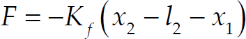
where m is the mass of the foot, K g and C g are virtual stiffness and viscosity coefficients of the ground, respectively, K f is the stiffness coefficient of the spring equipped on the foot. Symbols l 1 and l 2 are natural length of springs of the ground and foot, respectively. Symbols x 1 and x 2 are positions of the sole and the top of the foot spring, respectively, h is the difference between the predicted and actual ground levels, F is the reaction force from the foot spring. Since the stability after the foot landing on unknown terrain is main issue, only the state after foot landing is considered in this model.
In the following discussion, it is assumed that h, K g and C g are unknown, and F is measurable by using a force sensor.
In this subsection, landing controller is designed to land the foot on the unknown terrain without exceeding the impact force.
In this study, we assume that the top position of spring x2 can be controlled to arbitrary positions in real-time, and it is regarded as a control input. To make the foot position to be at the actual ground position while making the reaction force follows the desired value, the following controller is proposed.

where K P and K I are controller gains, x 2r is the desired position of the foot that corresponds to the predicted ground level, F r is the desired reaction force when the foot lands on the predicted ground. We assume that these parameters are given. This controller controls both the position and reaction force simultaneously by a single input signal.
If the actual ground level is equal to the desired position (i.e., h = 0), its dynamics can be written as follows:


Subtracting Eqs.(1) and (2) from Eqs.(4) and (5), respectively, we have an error dynamics as follows:


Substituting Eq.(7) into (3), we have

Using the Laplace transformation, Eqs.(6) and (9) are written as follows:


where initial values Δx1(0) and Δ͘x1(0) are assumed to be zero. ΔX1(s), ΔX2(s) and H(s) are the Laplace transformation of Δx1, Δx2 and h, respectively.
Substituting Eq.(11) into (10), we have a transfer function from H(s) to ΔX1(s) as follows:

where

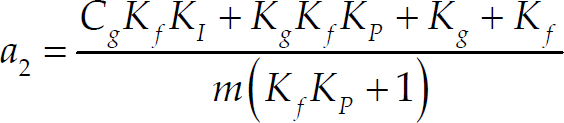


From the Lienard and Chipart's criterion, we can have the following stability conditions for Eq.(12).

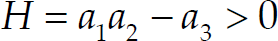
If controller gains K

Eq.(18) is clearly satisfied.
Equation.(19) can be rewritten as follows:


Because stiffness and viscosity coefficients of the ground characteristics are positive in general, the control system is stable regardless of the characteristic of ground. Therefore, stable landing on unknown terrain in which the characteristic parameters are unknown can be achieved by the proposed controller.
Next, we consider a new controller that includes a derivative term of reaction force as follows:

where x2PI is the control input given in Eq.(3), and K
D
is the controller gain. In this case, the following equations should be satisfied for the stability:


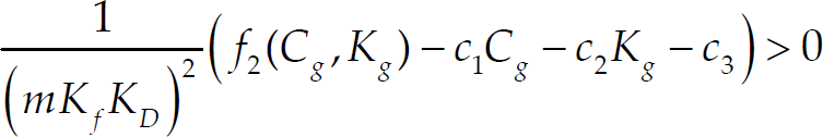

where f 1 and f 2 are positive functions.
It is difficult to always guarantee Eqs.(25) and (26) to be satisfied because negative terms depend on characteristic parameters of the ground K g and C g . Therefore, in case of using the derivative of reaction force, robust landing control is not achieved.
The proposed PI controller does not require any derivatives of the reaction force. This property improves control system stability because force signal generally contains high frequency noise.
To achive stable landing on unknown terrain, the foot should be placed at the actual ground position without exceeding the impact force. In this section, the performance of the proposed controller is examined.
Assuming that the value of h is constant, its Laplace transformation is given by

By using the final-value theorem, the final value of Δx1 and Δx2 are


Therefore, we have

From the above equations, it can be concluded that the foot position is converged to the actual ground position. In addition, from Eq.(7), the reaction force F is converged to the reference F
r
, that is,
To confirm the effectiveness of the proposed landing control, simulation is conducted by using the ODE (Open Dynamics Engine) (Smith, R., 2000) (Matsuda, T., 2007). A geometric model of foot based on Fig.2 is created as shown in Fig.4.

Simulation model
The initial height of the foot from the ground (x1(0) - h) is set to 0.10 [m]. Mass of the foot is 0.35 [kg], and the stiffness constant of the foot spring K f is 5000 [N/m]. The sampling period of landing controller is 10 [ms].
The desired reaction force F r is given as follows: First, it increases linearly after foot landing. Then it converges to a constant value F rmax = 20 [N]. The reference trajectory of the foot position is designed by using Eq.(2) so that the desired reaction force is achieved after foot landing.
Although the force sensor measurement is expected to be zero before foot landing, it has a non-zero value due to the displacement of the spring equipped to the foot. To solve this problem, it is assumed that the foot lands to the ground after a middle point of the reference trajectory of foot position, and the landing control starts at this point. Because the measured reaction force contains noise, the signal is filtered by a low pass filter (LPF), and it is used for the feedback signal. The cut-off frequency of the LPF is set to 100 [rad/s].
First, to verify the effectiveness of spring, the impact force in a model in Fig.2 is compared with that in a model in which the spring is replaced by a rigid link. The comparison result is shown in Fig.5, where h = 1 [cm]. Although large impact force occurs in the rigid link case, it is well suppressed and a gentle response is obtained by using the spring.

Comparison result of impact forces
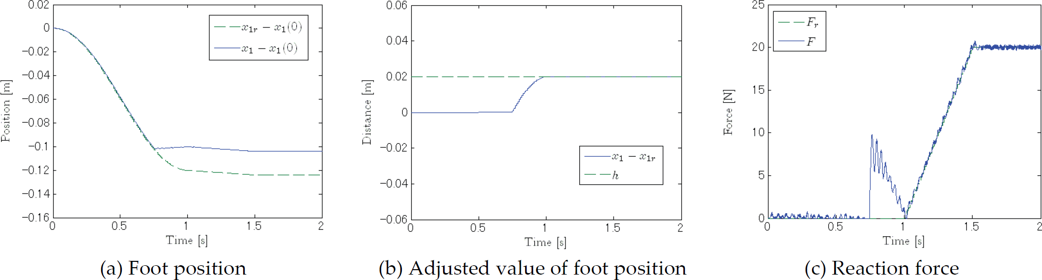
Next, the effectiveness of the proposed controller is verified. The height of the predicted ground is changed to 0.14 (+4cm), 0.12 (+2cm), 0.08 (−2cm) and 0.06 (−4cm) [m], while the actual ground level is 0.10 [m]. The simulation results are shown in Figs.6–9. In this simulation, both K

Landing control result (h=+4cm)
Landing control result (h=+2cm)

Landing control result (h=−2cm)
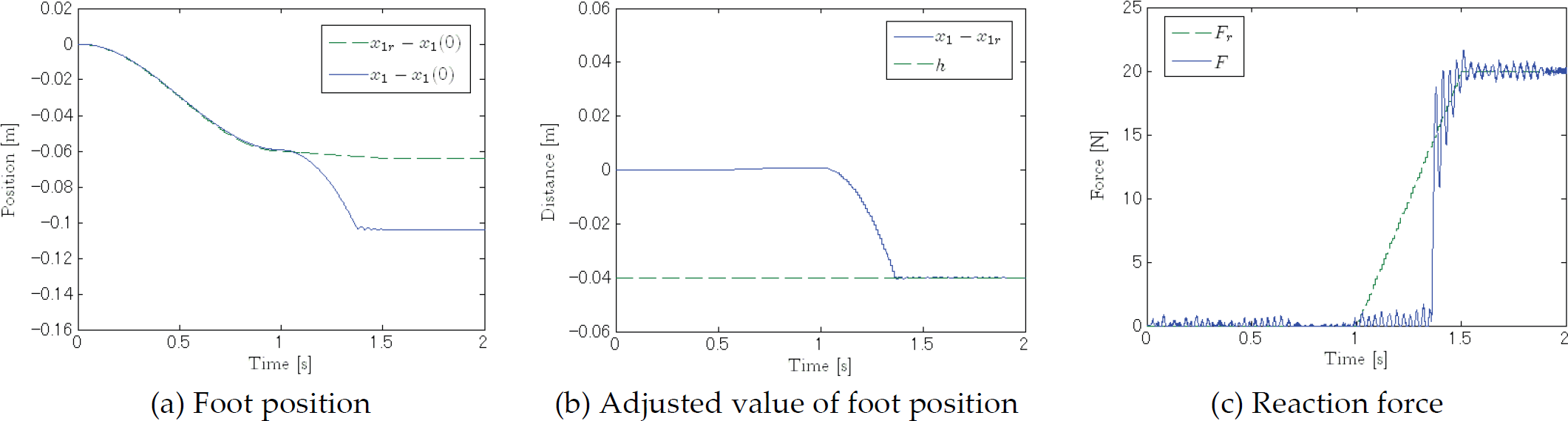
Landing control result (h=−4cm)
In Figs.6(c) and 7(c), the impact force is suppressed in case of the large deviation (h = +4[cm]) as well as the small deviation (h = +2[cm]). In addition, the foot position converges to the actual ground position. To further reduce the magnitude of impact force, the sampling period should be smaller because the impact force reaches about 8.2 [N] in 10 [ms] after foot landing in Fig.7(c).
The stable landing is also achieved by modifying the foot position when the actual ground is lower than the predicted one as shown in Figs.8(a) and 9(a). In addition, it seems that the reaction force follows to reference value without increasing the impact force in Figs.8(c) and 9(c). The reaction force fluctuates because it is very sensitive to the foot position. The magnitude of the fluctuation is small enough so that the stability is not deteriorated.
It is difficult to suppress the momentary impact force by using the conventional control when the difference between the predicted and actual ground level is large. In addition, theoretical argument on the stability and the performance of control system has been little made.
In this study, to achieve stable landing to unknown terrain, we have proposed a landing control for the PCFS. In addition, the stability and control performance are analyzed based on a two-dimensional model of the landing.
The proposed controller can achive stable landing by modifying the foot position based on the reaction force measured with the force sensor. The proposed controller can be easily implemented because derivatives of the reaction force are not required. Furthemore, it has been shown that the proposed controller provides the robust stability and performance with respect to variation of ground characteristics. The effectiveness of the proposed control to unknown terrain is demonstrated by using a dynamics simulatior.
Footnotes
6.
The authors would like to thank Mr. Russell L. Smith who developed Open Dynamics Engine employed in this study.