
Abstract
Most walking controllers for biped robots are based on a synchronized phase-based structure, where trajectories are executed following predefined timing constraints. This inherent fixed time dependency makes humanoid robots extremely susceptible to irregularities in terrain compared to their biological counterparts. We present an event-based control strategy which incorporates a time-variable phase to help deal with unexpected early and late contact situations. It results in an improved robustness against such scenarios, as shown by simulation results of our robot Lola.
Introduction
One of the main motivations behind humanoid locomotion research is the ability to navigate in all kinds of terrains. However, humanoid robots are still not ready to work robustly outside laboratory conditions. 1 Some of the factors that make walking control particularly difficult are the high number of degrees of freedom and underactuation due to unilateral contact with the ground. A popular approach to solve this problem consists of using a reduced robot model 2,3 and analyzing the simplified dynamics between the center mass and the center of pressure, also referred to as zero moment point (ZMP). 4 Solving these reduced dynamic equations allows one to achieve real-time motion generation. In a nutshell, this is done by first defining foothold positions and timings, and then generating the trajectories for the ZMP and center of gravity (CoG) followed by the inverse kinematics. 2,5 –7 Feedback control is introduced to compensate for modeling errors and external disturbances. 8 –11 In order to walk over uneven terrain, a perception system is introduced, which generates an environment model. Using this model, a search algorithm is used to find viable footstep locations and then motion planning can continue as before, taking height variation into account via heuristics. 12 –17
In all works cited above, knowledge about the ground location is assumed and ground contact timing is predefined. Therefore, even small ground location errors have a great effect on this kind of control, 18 especially when compared to their human counterparts. 19 By planning the step durations beforehand, different kinds of errors (e.g. in perception, modeling, or control) may all result in an early contact (EC) or a late contact (LC) with the ground. Thus, the planned and real walking phases can never be perfectly synchronized. Typically, control and modeling errors as well as small perception errors in laboratory conditions can be compensated using feedback control. This is possible when the robot’s walking is either quasi-static 12,15 or dynamic at slow moving speeds. 13,14 Nevertheless, perception errors become larger when performing dynamic walking at higher speeds or even when walking over other kinds of nonrigid, non-flat terrain, such as grass or stones. 18 Some authors presented methods for quick trajectory regeneration 6,7 during dynamic walking that are based on balance compensation without changing the step duration. Different strategies for online modification of ZMP trajectories were proposed for the HRP-2 robot that allowed it to dynamically walk over carpet tiles, though at low walking speeds. 11 Other authors treat these errors as disturbances to be compensated afterwards by quickly modifying future footstep locations, achieving fast dynamic walking. 20 –22
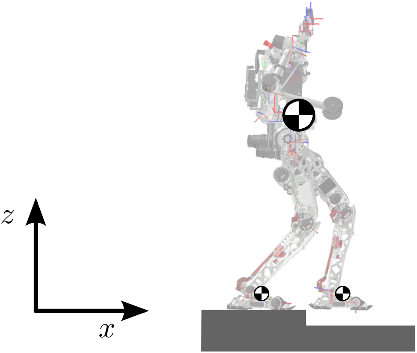
In contrast, in this article, we propose a flexible walking control that is intrinsically more robust against irregular ground. Instead of fixing the phase durations beforehand, our step duration is variable and depends on sensed contact with the ground, thus making sure that the planned and walking phases are always synchronized. The previous framework for our robot 19 implemented a specific phase to directly deal with detected ECs, which improved the robot’s robustness against unexpected obstacles. Now we present a walking controller which deals simultaneously with both EC and LC situations directly at the motion planning stage (in contrast to using feedback control). Our resulting control adapts the walking phase and motion to a direct ground contact detection, improving the robustness of our robot Lola (see Figure 1) against irregular terrain.

Photo and kinematic structure of the humanoid robot Lola with an RGB-D sensor mounted on top.
Other authors have also proposed phase-switching mechanisms for walking control. Some authors presented biologically inspired central pattern generators (a review of them can be found in the previous work 19 ) which have not yet been successfully applied to full-sized humanoid robots as far as the authors know.
A very interesting control strategy for dynamic walking directly depends on the position of the upper body instead of time. 23 This approach was further developed for planar robots, 24 where point feet cause an unstable degree of underactuation at the foot–ground contact. By introducing virtual constraints that can be tracked by the position controller, the dynamics of the robot are reduced to its internal dynamics, also called hybrid zero dynamics due to the hybrid nature of the biped system. 25 Even though the robot’s motion does not include statically stable poses, orbital stability of the periodic motion can be achieved by enforcing stable zero dynamics. The authors present a solution which includes inequality constraints in an optimization problem. 26 With this strategy, stable dynamic motion over rough terrain was demonstrated with planar robots. 27 Although this approach shows an intrinsic robustness against uneven terrain, it is not directly applicable to nonplanar robots 28 and is not compatible with existing three-dimensional walking controllers.
In a more related approach, other authors also use contact with the ground as a phase-switch mechanism, but they expect it inside a fixed time window. 29 More recently, a robot capable of walking over irregular terrain was presented. 30 It shows impressive results but uses a completely different strategy for dynamic walking control based only on controling the contact forces of the legs against the ground.
In contrast to the methods cited above, we present a method that can be easily implemented in other ZMP-based systems. It allows making the controller more robust against irregular terrain by eliminating the fixed timing restriction of phase switching, using direct ground contact detection instead. The article is organized as follows: In the following section, we give an overview of our walking control, including the previous phase modification strategy 19 ; later, we focus on our new proposed time-variable phase for LCs; finally, we validate our system using our multi-body simulation system. The article concludes with a discussion of the limitations and future work.
System overview
In this section, we give an overview of our hardware and control framework, followed by the modifications to the walking controller for handling EC and LC scenarios.
Hardware
The Lola humanoid robot, as shown in Figure 1, is 1.8 m tall and weighs approximately 60 kg. It has 24 position-controlled, electrically actuated joints. Along with the joint encoders, it has the following additional sensors: an Inertial Measurement Unit (IMU) in the upper body, force–torque sensors in each foot, and contact sensors in the foot soles. A standard RGB-D camera is mounted on top, which is not used throughout this article. The control system runs on QNX-RTOS. For more details, see the work of Lohmeier et al. 31
Control
As explained before, our ZMP-based walking control follows a hierarchical structure which is highlighted in Figure 2. It is mainly divided into a planning unit and a feedback control. The planning unit gets the walking parameters, such as step length and desired velocity, from the user’s input. A navigation module takes the walking parameters and collisions with the environment into account to generate footstep locations for the next several steps. 32 These are optimized in the parameter optimization module by considering the robot’s kinematics. 17 The walking pattern generation module is in charge of generating the robot’s ideal trajectories. These are then modified in real time by the feedback control module 9 for walking stabilization using the IMU and force–torque sensor information.

Lola’s real-time walking control system.
A state machine is in charge of defining the walking state, which defines the dynamics of the system. The different walking states depend first on the intended action (e.g. start/stop walking) and the planned contact state (e.g. single support (SSP)/double support (DSP)) and are synchronized with predefined timings. 33 These determine the phase of the walking controller and thus the control strategy according to the assumed contact state. For the purpose of this article, we will focus on the two main phases of periodical walking: SSP and DSP (see Figure 3).
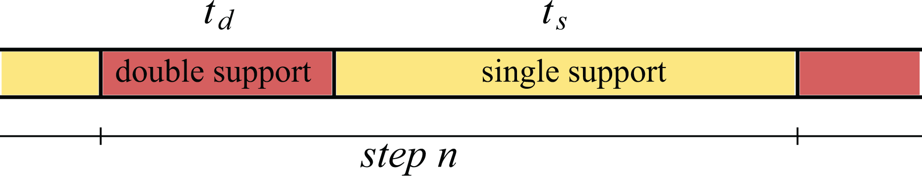
Main walking phases during ideal walking. During one step, the robot transitions between a DSP (duration t d) and an SSP (duration t s) contact state. Step duration is as planned. DSP: double support; SSP: single support.
Walking pattern generation
We model our robot
3
using one mass for the upper body and two small masses at the robot’s feet to represent the dynamics of the legs (see Figure 6). The whole system can be written as

where
Swing foot: This is parameterized by piecewise quintic polynomials between footstep positions, where it reaches zero velocity and acceleration.
ZMP: It shifts linearly between both feet during the DSP and along one foot during the SSP.
CoG: The trajectory is generated from the ZMP reference trajectory and (1). The boundary value problem is solved by spline collocation.
Load distribution: It calculates the load factors for both feet based on ZMP data.
9
During the DSP, the load distribution is shifted linearly between both feet.
In our original system, 33 as well as in most humanoid robot controllers, the timings for these phase transitions are fixed (see Figure 3) independently of the exact time the foot touches the ground. In our work, we add two event-based transition phases that react to the sensed ground contact, adapting the walking pattern generation and making the step duration effectively time variable. Changing the step duration results in a displaced CoG: If the step duration is shortened or extended, the CoG will be behind or ahead its planned position with respect to the feet accordingly. In order to compensate for this effect, the following step is adapted accordingly, as explained in the following.
EC response
Previously, an additional impact phase was introduced that is activated when a contact with the ground is detected during the SSP.
19
As shown in Figure 4, the state machine switches to the impact phase through this EC event, thus shortening the step’s duration


EC response. The step is interrupted and the state machine switches to the impact phase (where the robot is in a DSP state) for the rest of the planned step duration. EC: early contact; DSP: double support.
ts and
LC response
In this work, we present a walking controller which combines the existing impact phase with a new glide phase that specifically targets an LC scenario. This phase deals with an unpredicted, extended SSP state of the robot until a contact with the ground is detected, thus extending the step’s duration as seen in Figure 5. As explained before, the following DSP is shortened to prevent a displaced CoG motion


LC response. The step is extended by switching to a gliding phase, until contact with the ground is detected and the DSP can start. LC: late contact; DSP: double support.
where the duration of the glide phase tg is the time from the end of the SSP until the contact is detected, td and
Time-variable phase for LC
In an LC scenario, the predefined phase-switch timing results in the planned ZMP making the transition between both feet before the swing foot is in contact with the ground. The robot can tilt over when the ZMP reaches the limit of the stance foot. Additionally, the inclined state of the robot may cause an initial contact with the toe, causing further destabilization. 33 Our strategy in this scenario becomes keeping the robot from tilting over and achieving a firm contact situation between the swing foot and the ground, thus maintaining the ability to exert torque against the ground. This translates into keeping the ZMP inside the stance foot and maintaining the upper body in a vertical orientation, obtaining less strained walking. In this section, we explain the behavior of our time-variable glide phase throughout all stages of the walking pattern generation (see the previous section) to achieve this goal. These are the ZMP, swing foot, and CoG trajectory generation as well as force control and a necessary footstep replanning. For the sake of simplicity, we will limit our analysis to the sagittal plane (Figure 6), as it is equivalent for the frontal plane.
Robot and three mass model at the end of the SSP in an LC scenario—sagittal plane. SSP: single support; LC: late contact.
ZMP trajectory generation
Similar to the normal DSP, during the glide phase, the ZMP is shifted until the boundary (with a safety margin) of the stance foot (in the forward or x direction)

for t ∈ glide, where xP is the location of the ZMP (the y component stays constant). hg and cg are chosen to satisfy continuity with the SSP and xB is defined as a safety margin from the boundary. Instead of moving linearly between both feet, the ZMP is stopped until contact with the ground is detected, in order to keep the foot against the ground and maintain the ability to exert torque against the ground. When the DSP finally starts (after contact is detected), the ZMP motion is adapted to the new phase duration and continued

for t ∈ DSP, hg and cg are chosen such that the location of the swing foot is reached in
Swing foot vertical trajectory and load distribution
By the end of the SSP, the ground is expected and the swing foot’s vertical motion is stopped. As there is no information on where the ground may be, planning a vertical motion to reach the ground becomes difficult. However, if nothing else is done, the foot then stays in the air instead of reaching the ground. Instead, we decide to keep it stopped and let the force control (which can react to a contact with the ground more quickly) move the foot instead. The load distribution is then shifted between both feet, just as it would be during the DSP. More details can be found in the previous publication. 9
CoG trajectory generation
By the end of the SSP, the CoG is located ahead of the stance foot. In order to keep the ZMP from leaving the support polygon, the CoG position is integrated further in equation (1). The inputs of the equation (
Swing foot horizontal trajectory
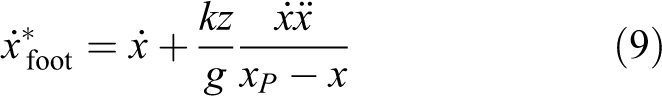
Note that a swing foot horizontal motion can easily be taken into account by (1) while generating the CoG trajectory. For the swing foot’s horizontal trajectory, we consider the linear inverted pendulum model 35

where

where

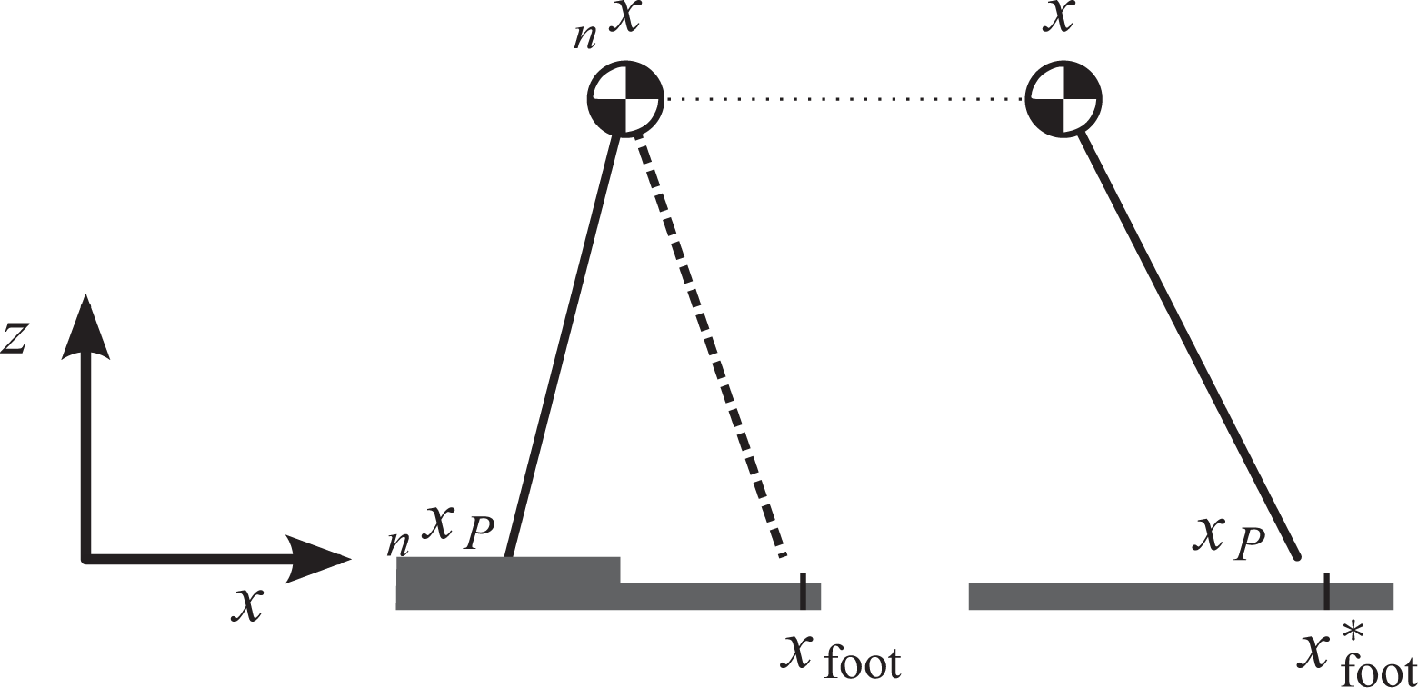
The swing foot horizontal trajectory is generated by analyzing the orbital energy of the linear inverted pendulum model. Left: reference energy at the end of the SSP. Right: an accelerated CoG requires a displaced pivot point to slow it down. SSP: single support; CoG: center of gravity.
where xfoot and
Footstep replanning
Even though the swing foot horizontal motion helps to reduce the effect of an accelerated CoG, its high speed can still have a destabilizing effect on further steps. If the CoG velocity increases beyond a certain margin, the next footstep location is also modified in order to slow the robot down to the planned walking speed. In our implementation, the footstep replanning is activated when t g > 0.2 s.
Again we use the orbital energy criterion energy and compare the energy at the end of the SSP for both steps

where we take the planned values of
Results
We validate our presented control strategy with our multi-body simulation for the Lola robot. 33 It handles unilateral and compliant contacts with the ground and takes motor dynamics and control loops into consideration. A video of the simulations can be found at https://youtu.be/FPpyDLKVlCY.
The first scenario we consider is an unexpected LC. The robot starts walking on a platform which abruptly ends after a few steps. For different heights, we compare simulations for the following: (a) the normal control system (consisting of the previously described walking pattern generation strategy without either EC or LC response 33 ), (b) only the impact phase active, 19 and (c) both impact and glide phases active (this work).
Several simulations with varying parameters were performed. It is confirmed that the impact phase shows a consistent improvement with respect to the normal control even in LC scenarios (as was previously shown 19 ). The reason behind this is that due to the LC the robot tilts, resulting in an EC for the next step where the impact phase becomes relevant. Additionally, it is observed that adding the glide phase leads to better results than both previous cases, as the effect of the initial LC is reduced before the next step is reached. This behavior is explained in greater detail in the following.
In Figure 8, a screen shot of the normal and “impact+glide” cases for the same platform height is shown. It can be seen how the glide phase helps to maintain the ZMP position and the upper body inclination while the ground has not been reached. In terms of robustness, the robot can also consistently overcome a higher change in the platform height without tilting over. In order to test this, simulations were performed for each control mode by sequentially increasing the platform height by 0.1 cm (starting at ground level) until the robot falls down or a joint limit is reached. The maximum height difference which it can safely overcome can be seen in Table 1.
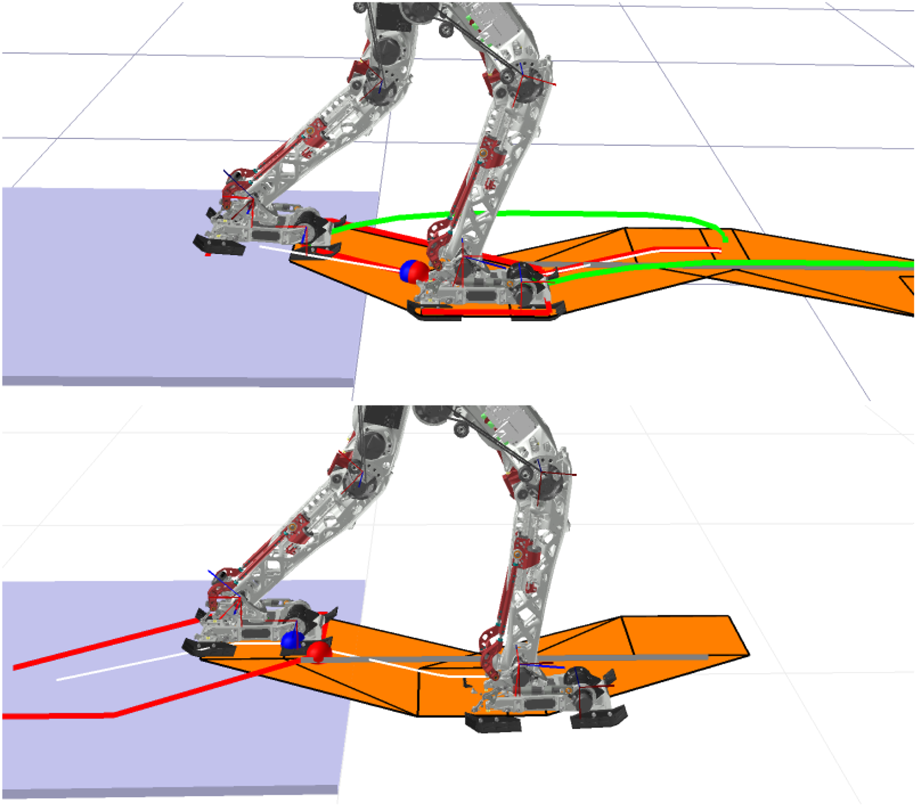
Simulation of an LC scenario (3-cm height in this case), before the swing foot touches the ground. Top: normal control. Bottom: impact and glide phases active. The planned footstep positions, along with the support polygons (orange), are projected on the expected ground. The glide phase keeps the ZMP (red) inside the actual support polygon while accelerating the swing foot and CoG away from their original trajectories. LC: late contact; ZMP: zero moment point; CoG: center of gravity.
Robustness.

As discussed in the previous work, we consider the upper body orientation as an indicator of the robot’s stability. 18 In Figure 9, we plot the upper body orientation for two exemplary height values to compare the different cases. The normal control results in the robot tilting over for all height values over 3.4 cm (see Table 1). Therefore, its result is only plotted for the smaller height value, where the normal control and impact phase show consistent behavior during the LC up until the next contact with the ground (t ≈ 8 s). Afterwards, the impact phase prevents the robot from tilting backwards and maintains a smaller value for the upper body orientation henceforward. In contrast to both previous cases, the glide phase already maintains a low value of the upper body orientation during the LC, preventing high values which could lead to the robot tilting over (this effect can be better appreciated in the bottom plot). The glide phase results in a less pronounced EC by the next step and a less strained walk than both previous cases.

Upper body inclination (around the y axis) for a 3-cm (top) and a 7-cm (bottom) LC scenarios with different control strategies. The vertical line indicates the end of the SSP. The normal control is not shown for the larger height value as it results in the robot tilting over. LC: late contact; SSP: single support.
As a final scenario, we consider an unexpected obstacle after the platform, to also analyze how the glide phase performs in an EC situation. A screen shot of the experiment is shown in Figure 10 and the resulting upper body orientation can be seen in Figure 11. Again the normal control is not shown as the robot tilts over. Similarly to Figure 9, the introduction of the glide phase maintains a low value for the upper body orientation during the LC. This time, it becomes even more relevant as it allows the robot to return to its original walking state more quickly, thus being able to overcome the latter obstacle. Without the glide phase, the robot does not recover in time and tilts over after encountering the obstacle.

Simulation of complex scenario. A few steps after a 6-cm LC, there is an unexpected 4-cm obstacle (the obstacle location is adapted so that it is directly met by the swing foot in both control cases). LC: late contact.

Upper body inclination (around the y axis) with different control strategies for a combined scenario: a 6-cm LC followed by a 4-cm EC. The vertical line indicates the end of the SSP before the LC. The normal control is not shown as it results in the robot tilting over after the LC. Without the glide phase, the disturbance becomes so large that the robot tilts over after the EC. LC: late contact; EC: early contact; SSP: single support.
Conclusions
In this article, we presented a walking controller for ZMP-based systems that is inherently robust against unexpected irregular terrain. We compliment our previous framework 19 with an extra time-variable phase that specifically deals with LC scenarios. The result is an event-based walking controller with a variable step duration that depends directly on the detected ground contact. It improves the robustness of our robot Lola against irregular terrain and perception errors. Future work includes testing on the actual robot in more complicated scenarios. For some particular cases (e.g. unexpected narrow holes), the swing foot trajectory may be counterproductive. One possible solution would be the specific monitoring of horizontal contact (using the force/torque sensors) to better adapt the footstep trajectory. Additionally, a more reactive and comprehensive force control strategy could yield enormous benefits.
Footnotes
Declaration of conflicting interests
The author(s) declared no potential conflicts of interest with respect to the research, authorship, and/or publication of this article.
Funding
The author(s) disclosed receipt of the following financial support for the research, authorship, and/or publication of this article: This work is supported by the German Academic Exchange Service (DAAD), the German Research Foundation (DFG) - project BU 2736/1-1 - and the Technical University of Munich (TUM) in the framework of the open access publishing program.