
Abstract
We present a novel open-source 3D-printable dexterous anthropomorphic robotic hand specifically designed to reproduce Sign Languages’ hand poses for deaf and deaf-blind users. We improved the InMoov hand, enhancing dexterity by adding abduction/adduction degrees of freedom of three fingers (thumb, index and middle fingers) and a three-degrees-of-freedom parallel spherical joint wrist. A systematic kinematic analysis is provided. The proposed robotic hand is validated in the framework of the PARLOMA project. PARLOMA aims at developing a telecommunication system for deaf-blind people, enabling remote transmission of signs from tactile Sign Languages. Both hardware and software are provided online to promote further improvements from the community.
1. Introduction
In recent years significant advances have been made in Human-Robot Interaction (HRI). Hand gestures have been investigated as the most natural tools of interaction for human beings, and particularly for disabled persons.
Today, many robots explicitly mimic biological behaviour and are equipped with dexterous multi-fingered hands. Development of modern robotic hands has mostly focused on two main categories: prosthetic and grasping hands. Controzzi's robot hand [1] is a representative example of the state of the art in prosthetic, bio-inspired and tendon-driven robot hands. Tendon-driven solutions are widely used, from the Utah/MIT Dexterous Hand [2] to the more recent high-speed multi-finger hand [3]. The Yokoi hand [4] is an 18-DoF (Degrees of Freedom) tendon-driven robot hand, designed for grasping. The survey on bio-inspired dexterous hands [5] is a good starting point to deepen this research area. Despite the significant progress in the last decades, this area of research is still far away from developing realistic muscular-type fingers and generally realistic hand movements. Open issues are dexterity and overcoming cost constraints [6]. Examples of dexterous robot hands for humanoid robots are the Awiwi [7] and the Shadow hand [8].
Recently, some open-source robot hands have been proposed that leverage low-cost technologies such as 3D additive printing and open-source hardware such as microcontroller-based boards for building digital devices that can control physical devices (e.g., Arduino boards) 1 . Projects in this field typically aim to make robotic prosthetic hands more accessible to amputees. Examples are the Dextrus hand from the OpenHandProject 2 , the modular low-cost hand from OpenBionics [9], and the Model T hand from Yale [10], based on the original SDM Hand [11], which is however not anthropomorphic. It consists of four underactuated fingers with compliant flexure joints, driven by a single actuator through a pulley tree differential.
An interesting example of a low-cost 3D-printed robot hand is the InMoov project 3 , by Gael Langevin, which is “the first life size humanoid robot you can 3D print and animate”. The project is released under an open-source and open-hardware philosophy. Although it is a significant project, we argue that InMoov's hand lacks dexterity, since it has only one DoF per finger, so that it cannot be used in applications where more complex interaction is required, such as Sign Language (SL) reproduction.
Our work takes inspiration from the InMoov project, in particular the hand, to produce a novel robotic hand specifically targeted for SL reproduction. Firstly, we re-engineered the design in order to improve dexterity (adding additional DoFs needed for hand gesture reproduction). One of our major concerns was also to develop an entirely 3D-printable architecture, to keep costs as low as possible. Secondly, we improved the hand using a spherical parallel three-DoF joint as a wrist. We took inspiration from the Emperor Penguin Shoulder parallel architecture [12] for emulating the human wrist. Parallel manipulators provided, at the same time, less inertia and higher stiffness [13, 14, 15]; in addition, thanks to this architecture, we could introduce compact and simple mechanics.
Robotic hands have also been investigated for haptics-based interaction. Haptics can be a complementary communication means for HRI, in addition to vision and hearing. As an example, the PARLOMA [16, 17] project has the ambitious goal of designing a low-cost remote communication system for deaf-blind people proficient in tactile SLs (tSLs). Deaf-blindness is a multi-sensorial impairment that deprives people of sight and hearing. Hence, deaf-blind people can only communicate by means of tactile exploration. The leading cause of deaf-blindness is the Usher syndrome [18], which causes affected people to be born deaf and then gradually lose sight in adulthood. Affected people usually grow up in a deaf community, where they communicate through an SL. When blindness occurs, they naturally evolve their communication into a tSL-based mode, replacing sight with the sense of touch. The authors in [16] state that, at present, there is no technological solution allowing remote communication via tSLs: PARLOMA aims to fill this lack by using a haptic interface (a robot hand) that mimics movements of a remote signer captured through Computer Vision techniques. Hence, PARLOMA needs a dexterous anthropomorphic robotic hand with a large number of DoFs to replicate the complex movements that are typical of human hands. In addition, such a hand should be low-cost in order to be accessible to a large community of users.
Some robotic hands for deaf and deaf-blind communication have been proposed in the literature. The first attempt at creating a fingerspelling hand was patented in 1978 by the Southwest Research Institute (SWRI) [19]. Later, the Dexter hand was developed [20]. Dexter improved upon the hand built by the SWRI but the new version was extremely bulky and required compressed air to drive the pneumatic actuators. The whole hand had seven pneumatic actuators. Each finger was actuated by a single pneumatic actuator with a linear spring to provide some resistance and return. Both the thumb and the index finger had a second pneumatic actuator to perform complex letters. The most successful design seems to be RALPH [21]. This hand was built in 1994 by the Rehabilitation Research and Development United States Department of Veterans Affairs. While RALPH fixed many of the problems of the Dexter hand, it still lacked in ergonomics, being composed only of fingers, with no forearm and wrist, thus being inappropriate for HRI.

Mechanics of the proposed hands and fingers
In this paper we present a novel solution which outperforms the state of the art in many features, being equipped with eight DoFs plus a three-DoF spherical wrist. We implemented the controlling software in C/C++ based on the Robotic Operative System (ROS) [22] and tested the developed hand as a haptic interface for the PARLOMA project. Control software and 3D-printable designs of our hand are freely available online.
The remainder of the paper is organized as follows: Section 2 presents the developed solution in detail; in Section 3 we discuss the outcomes of an early validation study of our hand within the PARLOMA project; finally, Section 4 draws conclusions and presents future work.
2. The Developed Solution
The proposed solution consists of a 3D-printable anthropomorphic robotic hand designed to reach a high degree of dexterity.
In this section we describe the hand and forearm design (sub-section 2.1). We also present the kinematic analysis as well as the architecture of the wrist (sub-section 2.2) and the implementation of a first working prototype with its characterization (sub-section 2.3); finally, in sub-section 2.4 we briefly discuss the motivations behind our work and the pros and cons of relying on 3D printing.
2.1. Hand and forearm
With respect to the InMoov's structure, we keep the idea of the fingers being moved by motors placed in the forearm: bending/extension of each finger is obtained by means of a tendon (for bending) and a spring (extension), leading to three under-actuated joints. The ring and little fingers present an additional bending/extension joint in their base (i.e., contact point with the palm), placed at 45° with respect to the main finger axis to emulate the carpal-metacarpal bending. Abduction/adduction has been implemented for the thumb, index and middle fingers by means of tendons. Motion transmission has been improved by introducing nylon sheaths to reduce friction and provide greater flexibility in the positioning of the actuators, and consequently greater freedom in the design. Figure 1 depicts finger and palm mechanics.
Finger control is quite simple. The target configuration for each finger (k) is identified by means of three angles,
Abduction/adduction mechanical coupling is trivial, so that we can easily calculate

Controlling bending/extension is a little bit more complex due to underactuation, since one motor controls three joints. We chose to define the tendon cable-finger system with the following model:

which is linear for the γ parameters we had to estimate. To do so, we applied markers on the joints constituting a reference finger, so that we were able to evaluate the three βj angles. We related these values to the corresponding

Expressing the

we can construct the linear system, which we have solved relying on the method of the Moore-Penrose pseudoinverse, obtaining that

which leads to

without introducing a significant margin of error after approximations.
2.2. Architecture of the wrist
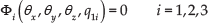
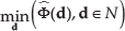
The wrist presented in this paper is a particular case of the spherical three-DoF parallel manipulator described in [23] and studied by [24]. Our own modified version, depicted in Figure 2, is inspired by [12].

Overview of the proposed spherical wrist
The wrist structure is formed by a triangular platform and three different legs (highlighted in blue, red and green colours in Figure 2). Each leg is composed of a proximal L-shaped link of angle
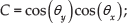
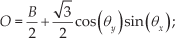
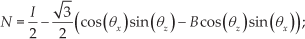
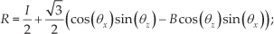
The motion axes of all the joints intersect in a unique fixed point (

The fixed reference frame (

while

where:
2.2.1. Inverse kinematic problem
Gosselin in [23] proposed an analytical solution to the Inverse Kinematic (IK) problem of a generic three-DoF spherical manipulator. In this paper, instead, we propose a novel geometrical approach to solve the IK problem. We believe that our approach is more intuitive; in addition, it can be graphically visualized step by step for easier understanding. To solve the IK problem we simply seek the intersection points (if any) among the three trajectory circumferences generated by the three distal links (red, green and blue circumferences in Figure 3) and the unique circumference produced by the three proximal links (orange circumference in Figure 3); therefore we only rely on simple equations describing circumferences in 3D space. Finally, it is only necessary to discard impossible solutions, or solutions that do not satisfy mechanical constraints of the wrist, to obtain the real solution to the IK problem. The input to the IK problem is the set of Euler angles (θx, θy, θz) while the expected output is given by the three actuated joints
The three vertexes of the wrist triangular platform (i.e., the three platform joint positions) can be computed as follows:

where

and
Let the distal link of the i -th leg connect to the i -th triangle vertex
The distal link circles can be expressed as follows:

where

where

where:


Each leg i allows two solutions for
The solutions for the actuated joints

where:


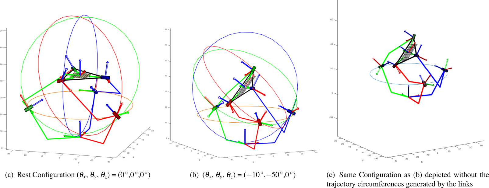
Kinematic of the wrist for two different configurations
2.2.2. Direct kinematic problem
The direct kinematic problem of a parallel manipulator is far harder to solve than the problem encountered in serial chains. Usually, no analytic solution can be found and one has to fall back on numerical methods. For a spherical manipulator the closure equation (4c) always holds. This equation leads to a system of three non-linear equations of the following form:
where non-linearities are present as products of trigonometric functions of roll, pitch and yaw angles. This system of equations does not allow an explicit solution for
2.2.3. Trust-region dogleg method
Given the square system of three non-linear equations in (13), the goal is to find a vector of Euler angles
Let

the minimization procedure tries to find a vector Θ that is a local minimum to
The basic trust-region approach defines a neighbourhood N around Θ and approximates Φ through a simpler function
the new point in the search space is then updated as

To solve the trust-region subproblem in Eq. (14) the Newton's method could be formalized through Eq. (16).

Unfortunately the Newton's approach has some drawbacks. The Jacobian

The choice of Eq.(17) is driven by the fact that the step
The Powell dogleg procedure [27] solves the trust-region subproblem in (17) defining two different steps: a Cauchy step (Eq. 18) and a Gauss-Newton step (Eq. 19). A convex combination of (Eq. 18) and (Eq. 19) yields the solution to Eq.(17) as stated in Eq. (20).


where α is a parameter needed to minimize (17),
Eq. (20) indicates the robustness of the trust-region dogleg method when the Jacobian is near to a singularity; in that case the step reduces to only the Cauchy step. Moreover the trust-region dogleg method behaves much better than the Newton's method when the starting point is far from the solution.
2.2.4. Test trajectory
To test the developed solution and the proposed control methods we carried out an experimental session aimed at challenging our IK and FK solvers. In particular, we used the famous lenmiscate of Gerono (also known as figure-8 curve, depicted in Figure 4) trajectory, which is converted into an equivalent roll-pitch-yaw trajectory that feeds the IK solver. The lenmiscate of Gerono can be expressed in the 3D space by the parametric equation in (21).

where
The actuated joint angles are then computed and directly fed into the FK numeric solver. The difference between the desired orientation angles and the outcome of the FK numeric solver defines the error of the FK algorithm along the given trajectory: the algorithm always converges for each point of the trajectory. The maximum error peaks at

Lenmiscate of Gerono test trajectory (a) Frame n. 30 (b) Frame n. 90

Error test of the trust-region dogleg numeric solver during the execution of a figure-eight curve trajectory
The trust-region dogleg method, like any other numerical solver, requires as input an initial guess of the solution. In our tests we always use
2.2.5. Inverse jacobian matrix
In three-DoF spherical parallel manipulators the inverse Jacobian matrix maps the Cartesian angular velocities (

The differentiation of both sides of the closure equation (4c) can be written as follows (the left superscript is discarded for the sake of readability):

The derivative w.r.t. time of equation (5) yields:
The three equations in (6) can be rewritten in general form as

where

The i -th row of the inverse Jacobian matrix can now be defined as:

2.2.6. Singularity analysis
The singularity analysis can be carried out rewriting the differential kinematic equation (26) as follows [23]:
where:

Type I singularities arise when

equation (30) implies that the three unit vectors
Type II singularities happen when
Figure 6 depicts the singularities of the proposed architecture.

Simplified version of the spherical wrist. (a) Type I singularity:
2.3. Implementation
We developed a left-hand prototype (Figure 7) of the proposed system based on Arduino UNO and analogue servo motors. The mechanical parts were 3D printed using FMD (Fused Deposition Modelling) technology [28] on an Ultimaker 2 3D printer 5 . Parts were developed in ABS (some small parts related to tendons), rubber (fingertips and palm shield), nylon (some mechanical servo parts), or PLA. The main printing parameters are reported in Table 1. About 23 hours of continuous printing were required to print all parts, and about eight hours to assemble them. The total cost (mechanics, printed parts and electronics) was about 280. CAD files of the proposed mechanics are available online 6 .
The control software
7
was developed in C/C++ based on the Robot Operating System (ROS) [22]. We developed a ROS node that takes as inputs the target angles of fingers
We tested positioning control by manually measuring angles of the wrist. The results show that error peaks at ±10°. We stress motors with continuous random motion to measure required power. In 50 minutes of continuous usage, the hand absorbs a mean of 40 W (at 5 V) and the servos reach a temperature of about 60°C.
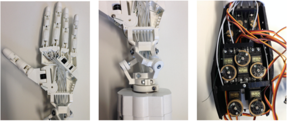
Detail of the implemented prototype
Main printing parameters used to print mechanical parts of the prototype

2.4. Discussion of 3D printing
The main aim of the paper is to demonstrate that modern technology is already mature enough to propose advanced robotic tools in a delicate sector, such as assistance to highly disabled people, needing high-precision mechanics and controls. To develop the first working prototypes of our robotic hand we decided to use 3D printing, which allows us to maintain very low development costs in the process of research and development. We argue that the same choice could be affordable also for sustainable production in the case of small volumes (less than 100 units per year). In addition, through 3D printing it would be possible to cheaply and quickly investigate the application of our designs in other fields, in which our design could potentially be a game changer, for instance the field of prosthetic hands or that of rehabilitative robotic aids. Another big advantage of 3D printing is that it potentially zeros the logistical cost compared to traditional industry.
Among all the existing technologies for 3D printing, we decided to use Fused Deposition Modelling (FDM), an additive manufacturing technology working by laying down material (principally PLA in our designs) in layers. All the mechanical components constituting our hand are individually optimized and designed to be moulded without the use of supports in FDM technology (e.g., fingers are separated into their constituent joints rather than being printed altogether). This makes our design highly efficient as regards the printing time and the cleaning of the components, while on the other hand requiring a slightly increased assembly time. We evaluated the possibility of switching to other technologies, such as Selective Laser Sintering (SLS), an additive manufacturing 3D printing technique that uses a laser as the power source to sinter powdered material, binding the material together to create a solid structure. Such technology would make the printing of fewer pieces very effective since it does not require any support while printing; however, the overall production cost would nevertheless be higher since SLS printers are typically expensive.
Although 3D printing has undoubtedly emerged as an increasingly important manufacturing strategy, we are confident that it cannot replace traditional manufacturing of parts through injection moulding or other mass-manufacturing means. One of the main laws of production states that the more is produced, the lower the costs per unit become, and this is especially true for plastic objects. Mass production of our proposed hand would surely require a paradigm shift to production through injection moulding. However, this shift would involve a high initial cost, a partial redesign of mathematical aspects (especially concerning tolerances) to fit the moulding techniques, and serious reassessment of all logistical aspects; these considerations fall outside the scope of this paper.
3. Experimental Results
In this section we report results on early validation of the proposed hand integrated in the PARLOMA framework to reproduce handshapes and signs from Italian SL (Lingua Italiana dei Segni, LIS). We used the same architecture of the experimental apparatus presented in [17]; we selected a subset of handshapes (from the LIS manual alphabet) and controlled the hand to reproduce them. Since this preliminary testing aimed to validate the ability of the hand in reproducing handshapes, we did not test the vision system.
As in [17], we focus on the LIS alphabet without loss of generality. It has been proven that signs from many different SLs can be grouped similarly. In [29], Battison defines four types of sign: i) one-handed signs, ii) two-handed signs with the same handshape performing the same movement, iii) two-handed signs with one active and one passive hand, both with the same handshape, and finally iv) two-handed signs with an active and a passive hand, each having a different handshape. Based on the complexity found in the three types of two-handed sign, Battison formulated his Symmetry and Dominance constraints, later improved by works such as [30], suggesting that there are restrictions on the allowable complexity of SL signs. Although Battison's constraints were originally based on American Sign Language (ASL), they have been successfully applied to lexicons of other SLs [31]. These works suggest that there are fundamental handshapes for SLs, identified as eight handshapes from the American SL (ASL) alphabet (namely A, Å, B, C, O, S, 1, and 5), as well as fundamental joint configurations: extended, flat, bent, curved, flexed, spread, stacked, and closed [32].
The proposed hand has been tested in reproducing sequences in LIS containing all the above-listed fundamental handshapes and joint configurations. Visual feedback-based validation provided by ten people non-expert in LIS proved that the hand can correctly reproduce all the fundamental handshapes. Experiments confirmed also that the hand can correctly reproduce all of the above-listed joint configurations but the two (flat and stacked) requiring the thumb to oppose against the palm.
The achieved results show consistent improvements in sign reproduction (see Figure 3) with respect to [17]. As an example, the implemented adduction/abduction DoFs allow letters to be distinguished as V, U and R. Moreover, the hand is also able to reproduce handshapes that involve the wrist joint, such as letters H and P, which are impossible to reproduce with the hand in [17]. We register a success rate in recognition of handshapes of almost 90%.
In addition, we performed a preliminary test of the proposed hand with an LIS expert (C. G.) and a blind person (A. P.) expert in Italian tSL (formerly deaf-blind, now hearing thanks to a cochlea plant). Both were individually asked to recognize handshapes performed by the hand (15 letters from the LIS manual alphabet were chosen, repeated in a random sequence). C. G. confirmed that all the handshapes were visually similar to the correct ones, while A. P. was able to recognize all the handshapes after a tactile exploration of the hand (she was given four seconds for each handshape). However, A. P. pointed out that finger positioning should be more precise to improve user experience. In particular, with regard to hand configurations where fingers are crossed (e.g., letter R in Figure 8), she pointed out that our hand should perform finger crossing in a more pronounced and evident way. We are working to improve our solution taking into account the valuable feedback received (e.g., by making the index and middle fingers more able to adhere while performing the R configuration).
Since our research project is at its very first stage of development, we preferred to conduct an early-stage validation of the system without directly including a large number of potential stakeholders. The encouraging early results provide a basis for a wider experimental campaign that will assess the proposed hardware with several end-users.
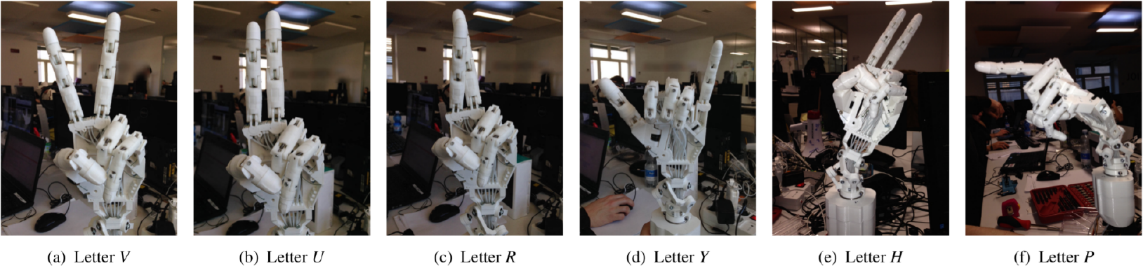
Some handshapes from the Italian SL's manual alphabets as performed by the developed hand
4. Conclusions and Future Work
This paper has presented a low-cost 3D-printable open-source anthropomorphic robotic hand specifically designed for Sign Language reproduction. We used the InMoove open-source project as a starting point. We improved the dexterity of the hand by introducing six additional DoFs: abduction/adduction for the thumb, index and middle fingers and a three-DoF spherical parallel joint for the wrist; in addition, we improved the general mechanics of the hand. We have published the entire project online under an open-source licence.
We provide early validation results by integrating the proposed hand within the PARLOMA framework; the experiments highlight the good accuracy of the proposed hand and control system, but also the importance of developing a more accurate and precise positioning system for fingers and wrist, which will be the focus of our future activities.
In the near future we have planned a test campaign that will involve capturing a big dataset of different handshapes, performed by a linguistic expert and representing significant gestures in SLs, and writing a script to let the robotic hand reproduce them. We will then administer a questionnaire for users to compare the robotic hand's accuracy in reproducing the handshapes. Finally, we will plan a more effective experimental campaign with experts in tSL.
Footnotes
5. Acknowledgements
This research has been partially supported by the “Smart Cities and Social Innovation Under 30” program of the Italian Ministry of Research and University through the PARLOMA Project (SIN_00132) and by a fellowship from TIM.