
Abstract
Multijoint industrial robots can be used for 3D printing to manufacture the complex freeform surfaces. The postprocessing is the basis of the precise printing. Due to the nonlinear motion of the rotational joint, nonlinear error is inevitable in multijoint industrial robots. In this article, the postprocessing and the path optimization based on the nonlinear errors are proposed to improve the accuracy of the multijoint industrial robots-based 3D printing. Firstly, the kinematics of the multijoint industrial robot for 3D printing is analyzed briefly based on product of exponential (POE) theory by considering the structure parameters. All possible groups of joint angles for one tool pose in the joint range are obtained in the inverse kinematics. Secondly, the nonlinear error evaluation based on the interpolation is derived according to the kinematics. The nonlinear error of one numerical control (NC) code or one tool pose is obtained. The principle of minimum nonlinear error of joint angle is proposed to select the appropriate solution of joint angle for the postprocessing. Thirdly, a path smoothing method by inserting new tool poses adaptively is proposed to reduce the nonlinear error of the whole printing path. The smooth level in the smoothing is proposed to avoid the endless insertion near the singular area. Finally, simulation and experiments are carried out to testify the effectiveness of the proposed postprocessing and path optimization method.
Introduction
The 3D printing is quite popular and growing rapidly with unique advantages in the field of prototype and mold manufacturing. 1 Industrial robots realize motion control by the change of joint space, which is more flexible than in Cartesian coordinate system. The combination of 3D printing and industrial robots can overcome the space limitations of traditional printing, as shown in Figure 1, and realize the high-precision printing of complex freeform surfaces.

The space range: (a) cartesian structure, (b) delta structure, and (c) robot structure.
At present, there are many kinds of research on multijoint industrial robots for 3D printing in the field of architecture. Zhu used ABB manipulator to build a flexible additive remanufacturing platform, which can implement reverse engineering for defective parts. 2 Keating and Oxman built a multifunctional and multimaterial processing platform using KUKA robot, which combines additive manufacturing and subtractive manufacturing. 3 Gosselin et al. deposited materials layer-by-layer on ultrahigh performance concrete through an extrusion printing head mounted on a six-axis robot. 4 Jean-Pierre et al. developed a novel five-axis robot for industrial large printing applications, which can print on fixed surfaces like walls or buildings. 5 Multijoint industrial robots for 3D printing are also used in the traditional manufacturing field. Zhang et al. used industrial robots to design manufacturing paths along curved surfaces, simulate, and print parts with curved surfaces. 6 Tam et al. adapted stress line additive manufacturing for structurally performative fabrication using a six-axis industrial robot. 7
Complex paths are the basis of 3D printing of complex surfaces of the robot. Postprocessing is the link between complex paths and printing robots. Therefore, it is a very important step in 3D printing technology. Denavit–Hartenberg parametric method was used in most postprocessing studies to establish the kinematics of robots. 8 –10 In this method, the cumulative error can increase with the increase of degrees of freedom (DOF). POE theory was also used for kinematics modeling. 11 –13 An et al. gave a generalized solution of kinematics problem based on POE, which can be used to analyze the kinematics problem of serial robots. 14 Ayiz and Kucuk used POE theory to solve kinematics problems of industrial robots. 15 POE theory allows global description of rigid body motion and greatly simplifies the analysis of mechanism. At present, the most common methods for solving inverse kinematics of robots are algebraic method, geometric method, and numerical method. Yahya et al. proposed a geometric method to find the optimal solution of inverse kinematics of redundant or hyper-redundant robots from infinite solutions. 16 Ananthanarayanan and Ordóñez took the analytical solution as the initial value and iteratively solved the objective function to obtain the solution of inverse kinematics. 17 Modern intelligent algorithms are widely used to solve inverse kinematics of robots with complex structures. 18 –22 Beheshti et al. adopted adaptive fuzzy logic method to determine inverse kinematics solution of a 3-DOF planar robot. 23 Yang et al. made the multisolution a mono-one with the application of genetic algorithm to search for all global optimum solutions. 24 Karlra and Prakash combined the neural-genetic method of artificial neural network with genetic algorithm to solve the inverse kinematics problem of planar robots. 25 These methods can obtain accurate inverse kinematics solutions but require a lot of training.
The inverse kinematics solution of robots is a multisolution problem. 26,27 At present, the criterion of shortest travel is generally adopted to select the appropriate solution, but the differences between joints and the actual requirements of each joint of the robot are ignored. Guang-Dao et al. proposed a criterion of weighted shortest travel and selected the appropriate solution by finding the minimum value of weighted Euclidean distance. 28 Xiao-Gang and Feng-Rong divided the result of inverse solution with the geometric attitude of the robot to facilitate selection. 29 A precise path is a prerequisite to ensure the accuracy and performance of the motion system. Macfarlane and Croft used a concatenation of fifth-order polynomials to provide a smooth trajectory between two way points. 30 Chen and Xi used freeform surfaces and CAD information to optimize deviation and generate trajectories through the trajectory integration algorithm. 31
Due to the nonlinear motion of the rotational joint, nonlinear error is inevitable in multijoint industrial robots. Considering the similarity between industrial robots for 3D printing and five-axis machine tools, nonlinear error can also be applied to the path optimization of industrial robots for 3D printing. Lin et al. used nonlinear error evaluation method with rotational tool center point (RTCP) interpolation and particle swarm optimization to solve the optimal setting problem of workpieces. 32 Li et al. used cubic spline to process tool paths, densified the data to reduce nonlinear error, and smoothed the paths. 33 Path optimization can be considered in postprocessing but can only be used to process printing code.
In this article, a postprocessing method based on nonlinear error is proposed to optimize the 3D printing path. Firstly, the kinematics of multijoint industrial robots is analyzed by POE theory, and all possible joint angle groups of a tool pose are solved in the range of joint angle according to kinematics. Secondly, the nonlinear error evaluation method is derived, and the principle of minimum nonlinear error of joint angle is used to select the appropriate solution of joint angle for the postprocessing. Thirdly, the path optimization of adaptive insertion of new tool poses is proposed to reduce the nonlinear error of the whole printing path. Finally, simulation and experiment are carried out on 3D printing system of a multijoint industrial robot.
The rest of the article is organized as follows: The second section establishes the kinematics model of multijoint industrial robots based on POE theory. In the third section, a multisolution selection method for inverse kinematics of the robot based on nonlinear error is presented. In the fourth section, an optimization method of 3D printing paths based on nonlinear error is proposed. Simulation and experiment will be carried out in the fifth section.
Kinematics of multijoint industrial robot for 3D printing
Forward kinematics of the robot is the basis of the postprocessing. The universal forward kinematics of multijoint industrial robots is established by POE theory. The structure parameters of the robot are introduced, and the positions of each axis in the tool coordinate system (TCS) are obtained.
Kinematics configuration analysis
Industrial robots need to set the origin. If the origin position is not accurate, the robot may have a high repeatability accuracy but not positional accuracy. The absolute origin of the robot is located at the intersection of the first joint axis and the common perpendicular of the second joint axis. Generally speaking, the printing origin is located on the printing platform. For most slicing software, the workspace of the cuboid will set the printing origin at the suitable vertex, while the workspace of the cylinder will set the printing origin at the center of the bottom circle. For this article, the printing origin is set at the vertex of the workspace by default. The relative position between the absolute origin and the printing origin is approximately measured. The position is substituted into the inverse kinematics of the robot, and the motion angle of each joint is solved to make the robot move to this position. At this time, there must be a deviation between the position of the printing nozzle and the printing origin. By adjusting the movement of the printing platform, the printing nozzle can be infinitely close to the printing origin so as to determine the printing origin of the multijoint industrial robot for 3D printing.
There are one base coordinate system (BCS), one TCS, and one workpiece coordinate system (WCS) of the multijoint industrial robot for 3D printing. The origin of TCS is set at the printing nozzle and the origin of WCS is set at the printing origin, as shown in Figure 2. The displacements of three axes calculated by the postprocessing should be expressed in TCS. Vector VU (Ux , Uy , Uz ) represents the position vector of the workpiece relative to the base. The position of axial line of A-axis is expressed as vector VA (Ax , Ay , 0), where Ax = −(a 1 + a 3 + a 4), Ay = 0. Vector VB (Bx , 0, Bz ) represents the position of B-axis relative to TCS, where Bx = −(a 3 + a 4), Bz = a 5−a 2. The position of axial line of C-axis is expressed as vector VC (Cx , 0, Cz ), where Cx = −(a 3 + a 4), Cz = a 5. Vector VD (Dx , 0, Dz ) represents the position of D-axis relative to TCS, where Dx = −a 4, Dz = a 5. Four vectors are structural parameters of the robot. Vector VW (Wx , Wy , Wz ) represents the position vector of the workpiece relative to the base, where Wx = −(a 1 + a 3 + a 4), Wz = a 5−a 2−d 1. The vector VU (Ux , Uy , Uz ) represents the position vector of the workpiece relative to the base. As a result, vectors VA , VB , VC , VD , VW , and VU can be obtained.
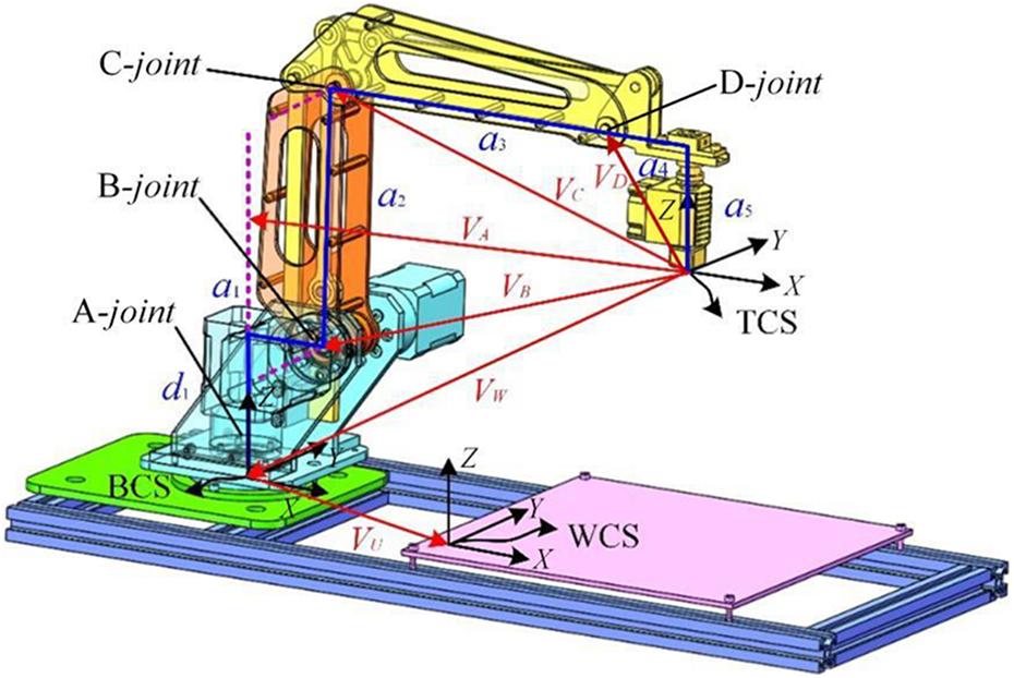
The structure parameters of the multijoint industrial robot for 3D printing.
Forward kinematics based on POE
The clear geometric meaning of POE theory makes it an effective tool for kinematic modeling. One twist can represent the motion of one rigid body. The twist coordinates can be expressed as in equation (1)

where ω is the unit vector of the rotational axis; ν is the linear velocity of the rotational motion; vector ν can be obtained as ν = p × ω; p is the position vector in the base for a point fixed on the axis; and the exponential matrix of the twist is represented as in equation (2)
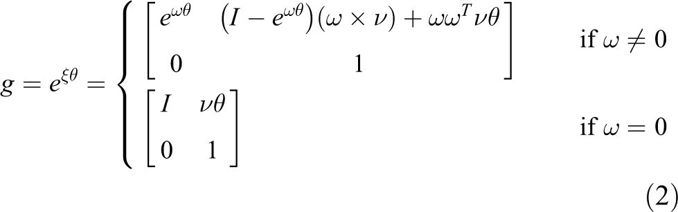
where eωθ could be calculated by the following formula

Using the POE formula, the forward kinematics of multijoint industrial robots with n joint can be obtained as in equation (4)

To obtain the position of the printing nozzle relative to the workpiece, the WCS was originally set as the global coordinate system. However, to facilitate the inverse kinematics solution, the BCS is set as the global coordinate system. Finally, the kinematic POE equation is coordinately translated, and the position of the printing nozzle relative to the workpiece can still be obtained. As shown in Figure 3, the order of the open chain is base→A-joint→B-joint→C-joint→D-joint→printing nozzle. At first, motion twists and exponential matrices of all axes are established according to POE theory.

The kinematic chain of the multijoint industrial robot for 3D printing.
For rotary axes, the motion is rotational. The motion twist is the product of one unit twist and angular. In addition, twists can represent arbitrary straight line in space from the view of geometry. The motion twist of the rotary axis is expressed as in equation (5)
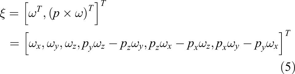
where p = [px , py , pz ]T represents the coordinates of one point in the global coordinate system. This point is in the rotation axis of the rotary axis.
In the kinematic chain of the multijoint industrial robot for 3D printing in “Kinematics configuration analysis” section, vectors VA , VB , VC , VD , and VW can calculate positions of A-joint, B-joint, C-joint, and D-joint in global coordinate system (BCS). As shown in Figure 3, point RA is the intersection point of rotation axis of A-joint. The coordinates of RA in BCS are RA = −VW + VA . Point RB is the intersection point of rotation axis of B-joint. The coordinates relative to BCS are RB = −VW + VB . Point RC is the intersection point of rotation axis of C-joint. The coordinates relative to BCS are RC = −VW + VC . Point RD is the intersection point of rotation axis of D-joint. The coordinates relative to BCS are RD = −VW + VD . Then, unit twists of A-axis, B-axis, and C-axis are expressed as in equation (6)

According to the order of the open chain, the transformation matrix of multijoint industrial robot for 3D printing can be obtained with the product of exponential matrix of each axis. The movements of all axes relative to their local zero positions are positive relative to the global coordinate system (BCS). Then, the POE formula of the tool relative to the base of the multijoint industrial robot for 3D printing is expressed as

where ξb
= ξt
= [0, 0, 0, 0, 0, 0]T represents the twist of the base and the printing nozzle, respectively. The attitude matrix is R = [n, o, a], and the position matrix is
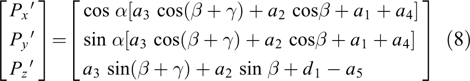
The 3D printing code is the position parameter of the printing nozzle in the WCS. So, the forward kinematics equations of the printing nozzle relative to the workpiece are expressed as

All possible solutions of joint angle in inverse kinematics
For the kinematics model of robots established by POE theory, the Paden–Kahan subproblem is needed to solve sthe inverse kinematics. It requires the TCS relative to the BCS. As shown in Figure 3, given that [Px, Py, Pz
]T is the TCS relative to the WCS, [Px, Py, Pz
]T is converted to the BCS and expressed as
Firstly, ignoring the periodicity of trigonometric functions and the stroke range of the rotation axis, one rotation angle a, b, and c of A-joint, B-joint, and C-joint is expressed as in equation (10)

where
Secondly, considering the periodicity of trigonometric function and the travel range of rotation axis, according to the structure of multijoint industrial robot, the stroke range of α is [−π, π], the stroke range of β is [−π/2, 3π/2], and the stroke range of γ is [−π, π]. The range of the inverse trigonometric function and the stroke range of the A-joint, B-joint, and C-joint are given in Table 1. For A-joint, when the range of α is [−π, π], the tangent function is shown in Figure 4. Thus, the stroke range of equations can be divided into four regions, and the dual solution of equations is given in Table 2.
The range of inverse trigonometric functions and the stroke of rotation axes.


The curve of tangent function when α is in the range of [−π, π].
The solutions of joint angle of A-joint.

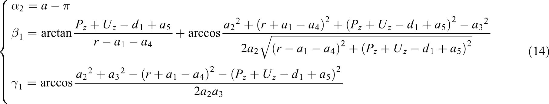
Combining the solutions of joint angles of A-joint, B-joint, and C-joint, the four solutions of (α, β, γ) are represented as follows. When Px
= 0,
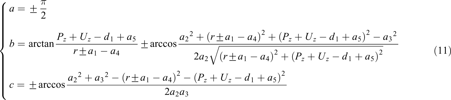
When Px
≠ 0,


Multisolution selection method based on nonlinear error
Nonlinear error evaluation based on multijoint industrial robot for 3D printing
The general software preprocessing generates a tool position file, which is the required printing path file. A continuous printing path is usually represented approximately by a set of consecutive line segments. Since the motion of the multijoint industrial robot in 3D printing process is converted into the motion of each motion axis, the actual motion trajectory is the composite trajectory of interpolation motion of each axis. As shown in Figure 5, there is a certain difference between the actual path and the ideal path, resulting in nonlinear error in 3D printing process of multijoint industrial robots.

Nonlinear error theory model.
When the interpolation calculation of multijoint industrial robot is carried out, the deviation between the actual composite trajectory of each axis and the ideal trajectory of path planning is defined as nonlinear error. Suppose that there are two adjacent path points Pi− 1 =(xi− 1, yi− 1 , zi− 1) and Pi = (xi , yi , zi ) on the trajectory, whose distance is D = |Pi −1 − Pi |. Assuming that the current feed velocity is F and the sampling interval is T, then

where n is the number of intervals required to cover the distance D. Note that n obtained from equation (16) might be a noninteger, which needs to be adjusted to the nearest integer by slightly adjusting the feed velocity F (still provided by n). For Pi −1 and Pi , the joint angles are Qi −1=(αi −1, βi −1, γi −1) and Qi = (αi , βi , γi ), and n intervals are inserted evenly between Qi −1 and Qi , as shown in Figure 6.

The interpolation of joint angle.
For the j’th interval (jϵ[0, n]), the joint angle Qi, j is
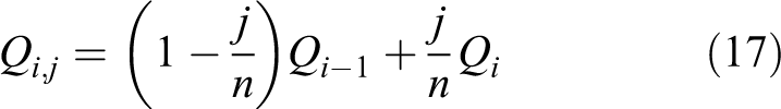
Each joint angle Qi, j = (αi, j, βi, j, γi, j ) can be solved by inverse kinematics equations (10) and (11) to get Pi, j . The distance εi, j from Pi, j to line segment Pi −1 Pi can be calculated. In fact, it is to solve the problem of the distance from a point to a line in space. It can be solved by vector cross multiplication, which is obtained by dividing the area of the parallelogram by the length of the base. So, the nonlinear error of the actual path point Pi , j is

Then, the maximum nonlinear error εi between Pi -1 and Pi is

Optimization of joint angle selection based on nonlinear error
The existence of a solution depends entirely on the workspace of the robot. In this workspace, there may be multiple inverse kinematic solutions of the kinematic equation. The more nonzero parameters of the connecting rod, the more ways to realize a certain target. However, the control of the robot needs a unique and exact solution. Therefore, the multisolution phenomenon of the robot will cause some problems, which need to be optimized for multiple solutions. If the obstacle avoidance requirement is not considered, the unique optimal solution can be obtained through the following steps.
The inverse solution of point A on the space path is solved to obtain m groups of solutions, which is Qi, k , where, k ϵ [1, m]. Given that the previous point is Pi −1, the appropriate inverse solution is Qi −1. According to “Nonlinear error evaluation based on multijoint industrial robot for 3D printing” section, n intervals are inserted between Qi −1 and Qi , and the forward kinematics of the n+1 angle value after interpolation is solved to obtain Pi, j, k , where jϵ[0, n]. εi, j, k can be calculated by equation (15), and the nonlinear error εi, k = max{εi, j, k , 0 < j < n, 1 < k < m} between Pi −1 and Pi is found therefrom. Finally, by comparing the nonlinear error εi value of m groups of solutions, the inverse solution corresponding to the minimum εi value is an appropriate solution of Pi .
Path optimization based on new tool pose insertion
Path optimization method
In the multijoint industrial robot for 3D printing, the printing path is generated by the path point file obtained by slicing software. The traditional path generation algorithm has defects, and the nonlinear error can make the actual print nozzle deviate from its ideal path, especially when the nonlinear error is too large. To avoid sacrificing the print quality, the path should be optimized in the postprocessing to reduce the nonlinear error in the printing path. It is necessary to select an appropriate error estimation method to determine whether to reduce the nonlinear error between two adjacent path points. If the error exceeds the allowable range, the optimization algorithm should be used; otherwise, the original generated path will be used for 3D printing.
Taking ε = max{εi ,0 ≤ i ≤ n} as the evaluation standard of nonlinear error, the nonlinear error between adjacent path points is calculated, respectively. If ε = max{εi ,0 ≤ i ≤ n} is greater than the allowable error value, a path point is inserted between adjacent path points, and then, the error between the adjacent path points after inserting the new path points is calculated to meet the requirements. If not, the new path points continue to be inserted until the calculated error between all path points meets the requirements. By inserting a new path point, the size of the printed step can be controlled, and the data of path points can be made dense so as to control the nonlinear error effectively.
Therefore, firstly, the adjacent points Pi and Pi +1 in the original print path file are denoted as Pa and Pb , respectively, and the nonlinear error ε between the two points is calculated. If ε is greater than the allowable error value [ε], a new path point between Pa and Pb is inserted, and this path point is marked as Pb . If ε is still greater than [ε], a new path point continues to be inserted between Pa and Pb , and this path point is denoted as Pb until the nonlinear error ε between Pa and Pb is less than the allowable value [ε]. At this time, Pb is replaced by Pa , and the next path point is denoted as Pb . Then, the above process is repeated, and the nonlinear error ε between two points is compared with the allowable error value [ε], until the error requirements are met between adjacent points Pa and Pb in the original path. Finally, Pi +1 and Pi +2 are denoted as Pa and Pb , respectively, and the above process is repeated until all path points in the original path point file are interpolated and optimized. It should be noted that acceleration and deceleration performance should also be considered to make the path points dense, otherwise, excessive insertion of path points will cause the jitter of multijoint industrial robots. The specific control flowchart is shown in Figure 7.

The schematic diagram of path optimization.
Smoothing in singular position
Singular configuration is an inherent characteristic of the industrial robot mechanism. There are two types of it. The first type is the boundary singular configuration, which appears when the robot actuator is located at the boundary of the working area. This singular configuration is not very serious, as long as the actuator is controlled away from the boundary of the working area. The second type is the internal singular configuration. When two or more joint axes are collinear, this kind of problem will appear, and this kind of singular configuration is quite difficult to deal with.
Therefore, the singular configuration must be avoided or processed near the singular point so that the robot can pass through the singular configuration on the premise of guaranteeing the working performance and motion accuracy. When the robot reaches the singular position, the 3D printing path optimization algorithm proposed in “Path optimization method” section is easy to fall into the situation of infinite interpolation.
To avoid endless insertions near or in the singular region, the maximum number of inserted points between two points is defined. The smooth level S is proposed to represent the smooth order of the inserted path points, and S max represents the maximum smooth level allowed. If S max is exceeded, the interpolation between the current adjacent points is stopped, and it is judged whether the next set of adjacent points is smooth.
Taking two points M and N on the path near or in the singular region as an example, where S max =2 is set. The first step is to evaluate the smoothness of the path between the two points of MN. According to the optimization algorithm in “Path optimization method” section, a new path point R 1 and its smooth level S 1 are obtained and inserted into the midpoint of the line MN, as shown in Figure 8(a). The second step is to smooth the path between MR 1. The new path point R 2 and its smooth level S 2 are still obtained first, and then optimized and inserted into the midpoint of the line MR 1, as shown in Figure 8(b). The smooth level is S 2 = 2. The third step is to smooth MR 2. Since S max = 2, the smooth level exceeds S max at this time, and then, the current interpolation is aborted. Similarly, when smoothing R 2 R 1, the smooth level also exceeds S max, and the same is not interpolated. Then, the path between the next set of adjacent points is smoothed, that is, R 1 N, as shown in Figure 8(c). Due to the smooth level limitations, R 1 R 3 and R 3 N do not need to be smoothed. At this point, the path between R 1 N has been smoothed. Figure 8(d) shows the final smooth of the path MN, and the maximum number of inserted path points is 3.

(a–d) The smooth steps for adjacent path points in singular area.
Simulation and experiment
Verification of multisolution selection method based on nonlinear error
Figure 2 is a structure diagram of 3D printing system with multijoint industrial robots. This position is its initial position, and at this point, VA = [−285, 0, 0]T mm, VB = [−220, 0, −56]T mm, VC = [−220, 0, 79]T mm, and VW = [−285, 0, −179]T mm. In this experiment, VU = [225, −70, 12]T mm. To verify the correctness of the multisolution selection method based on nonlinear error, two path points P 1 and P 2 are obtained from the 3D printing path, where P 1 = [165, 42, 120]T and P 2 = [165, 84, 120]T. And Q 1 = [14.2811, 92.7825, −142.7475]T is known. The verification of the inverse kinematics algorithm of the robot is performed according to the following steps.
According to the inverse kinematics formula in “All possible solutions of joint angle in inverse kinematics” section, all possible four groups of joint angle groups at the path point P 2 are solved, as given in Table 3.
According to “Optimization of joint angle selection based on nonlinear error” section, the interpolation interval is 10, and each joint angle group of the path point P 2 obtained by inverse kinematics can be used to calculate the corresponding joint angle interpolation. Then, the actual path points are obtained according to the kinematics, and nonlinear errors are calculated by equation (18), as given in Table 4. Similarly, the nonlinear error can be obtained by solving the remaining three sets of inverse solutions, as given in Table 5. From Tables 4 and 5, the nonlinear error of the entire path segment P 1 P 2 under all possible joint angle groups can be obtained, as given in Table 6.
The nonlinear error of the entire path segment calculated under all possible joint angle groups is compared. According to the principle of minimum nonlinear error, the nonlinear error calculated using the first group of inverse solutions is selected to be the smallest. So, the appropriate solution is the first group, that is, Q 2 = [26.9802, 87.2732, −137.2418]T. In the actual printing process, according to the motion stability of the robot and the restriction of the actual working range, a group of suitable solutions is selected using the optimum condition of minimum nonlinear error. The result is shown in Figure 9.
Four groups of solutions for inverse kinematics (unit: °).

Nonlinear error calculated using the first group of inverse solutions.

Nonlinear error calculated using the remaining three groups of inverse solutions (unit: mm).

Nonlinear error of the entire path segment P 1 P 2 (unit: mm).


The simulated position and pose of the robot: (a) The first solution, (b) the second solution, (c) the third solution, and (d) the fourth solution.
Verification of path optimization
The deer type specimen is selected as the experimental model, as shown in Figure 10, to verify the path optimization algorithm in “Path optimization based on new tool pose insertion” section. The original paths are obtained from slicing software. To verify the effectiveness of the algorithm, a section of contour code from the original path program is selected for simulation. The contour is shown in Figure 11. There are 20 path points along this path. The original path code needs to be postprocessed to generate the angle code that can be used for 3D printing. The relevant code is given in Table 7. The starting and ending points of the program segment are [30.830, 41.791, 1.300]T and [64.912, 70.010, 1.300]T, respectively, and the corresponding angle codes are [−6.29, 24.14, −107.66]T and [0, 21.30, −94.50]T.

Paths generating from slicing software.

The selected contour.
The contour code with 20 path points.
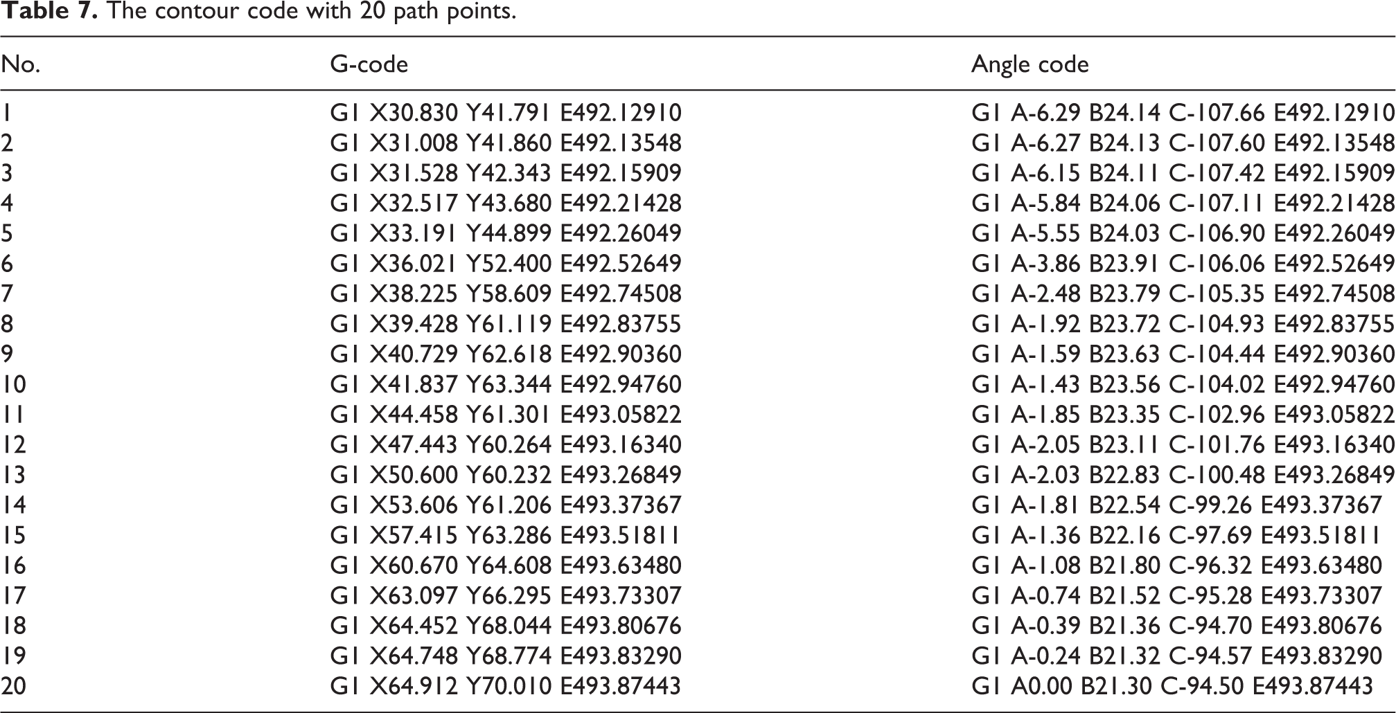
The inverse kinematics of these 20 points is solved to obtain their respective joint angles. According to robot motor interpolation and motion control algorithm, the actual running path of multijoint industrial robot is simulated, as shown in Figure 12, which is the comparison of ideal path and actual nonlinear error path. It can be seen that the actual path of some path points deviates greatly from the ideal path, which results in the actual contour of the 3D printing deviating from the ideal contour of the 3D printing part. After the path is superimposed layer-by-layer, the surface of the actual 3D printing part is rough and the printing quality is poor. The nonlinear error model established in this article is used to analyze the nonlinear error of this path and obtain the histogram of nonlinear error distribution, as shown in Figure 13. It is not hard to see that the nonlinear error of some path points is relatively large, and the average value of the nonlinear error is 11.47 μm.

Comparison of the ideal path and the actual path.

Nonlinear error distribution before optimization.
The allowable error is set as 5 μm, and the nonlinear error optimization method proposed in this article is adopted. When nonlinear error of a program is detected to be greater than the allowable error, the path point is inserted. It can be seen from Figure 13 that nonlinear error in sampling sections 6–7 and 11–17 is greater than the allowable error. Therefore, new path points should be inserted in these nine sampling points. The nonlinear error distribution after the nonlinear error optimized is shown in Figure 14. It can be seen that the nonlinear error is less than 5 μm, the nonlinear error is effectively controlled, and the sampling points are increased from 20 to 31, which is the reasonable densification of path points in the sampling segments, where the error does not meet the conditions.

Comparison of nonlinear error before and after optimization.
As shown in Figure 15, after inserting 11 path points between the path points with large nonlinear error, the actual running path of multijoint industrial robot tends to the ideal path. Figure 16 shows 11 path points at the specific insertion positions of this contour path. Therefore, it can be shown in Figure 17 that the 3D printing path optimization method based on nonlinear error can well solve the nonlinear error distribution problem in the actual printing process of multijoint industrial robots and play a role in optimizing the path. The contour code of the optimized path points is given in Table 8.

Example simulation effect diagram.

The contour selected.

The 3D printing system of multijoint industrial robot.
The contour code with optimization.

Experiment
Finally, on the 3D printing system of multijoint industrial robot, as shown in Figure 17, the optimized path generated by the 3D printing path optimization method is verified by actual 3D printing. In the actual 3D printing system, the “deer” type specimen shown in Figure 18 and the “plum blossom” type specimen in Figure 19 are also selected. For these specimens, the method proposed in “Path optimization based on new tool pose insertion” section is used to generate the printing path, and the layer height of the printing parameter is set as 0.2 mm. The printing material is poly lactic acid (PLA).

Printing experiment for “deer” type specimen: (a) the original one (b) the enlarged one (c) the optimized one (d) the enlarged one.

Printing experiment for “plum blossom” type specimen: (a) the original one (b) the enlarged one (c) the optimized one (d) the enlarged one.
The actual process of 3D printing is shown in Figure 17. The original printing code and the optimized printing code are, respectively, 3D printed with the 3D printing system. Figure 18(a) is the 3D printing part without path optimization. In the enlarged image of Figure 18(b), the nonsmooth path of the printed part is shown. Figure 18(c) is the 3D printing part after path optimization. In the enlarged image of Figure 18(d), the smooth path of the printed part is shown. The results show that the proposed path optimization method is effective.
Another printing experiment was carried out on the 3D printing system of multijoint industrial robot to verify the feasibility of path optimization method. The experimental conditions and parameters are consistent with the last one. Figure 19(a) is the part printed without path optimization method. It can be seen from the enlarged figure of Figure 19(b) that the printing path is not smooth. Using the proposed path optimization method, the printing path code of parts is optimized. The result of 3D printing is shown in Figure 19(c). In the enlarged image in Figure 19(d), it can be seen that the path becomes smooth. As can be clearly observed in Figure 19, the actual print track on the surface of the printed part is closer to the ideal print track, which confirms the feasibility of the 3D printing path optimization method.
Conclusions
Multijoint industrial robots-based 3D printing can be used for the high-precision printing of the complex freeform surfaces. The postprocessing is the basis of multijoint industrial robots for the 3D printing. This article proposes the postprocessing and the path optimization according to the nonlinear errors for the multijoint industrial robots-based 3D printing. The main contributions are as follows: All possible solutions of joint angles for one tool pose are presented in detail based on the precise forward kinematics of the multijoint industrial robot for 3D printing. The positions of all axes relative to the base are introduced into the kinematic chain of the robot. The periodicity of trigonometric function and the stroke range of joint angle are considered. The nonlinear errors of tool poses are calculated based on the interpolation and the forward kinematics for the evaluation of all possible solutions of joint angles. The solution with the minimum nonlinear errors is chosen as the appropriate solution of joint angle. One inserting new tool poses-based path smoothing method is proposed to reduce the nonlinear error of the whole path. One new path point is inserted at the midpoint of the adjacent points if the smoothing is insufficient. The smooth level of each point is proposed to avoid the endless insertion near the singular area.
In this article, the industrial robot only with three joints is used and the solutions of joint angles for the tool orientations are not proposed, which is important for the printing of the freeform surface. In addition, the maximum available value of the smooth level is not presented. It is related to the smoothness of the whole path. In the future, further research will be carried out in these aspects. The postprocessing of the industrial robot with six joints will be proposed. In addition, the error calibration and error compensation of the robot will be proposed to improve the accuracy of 3D printing.
Footnotes
Declaration of conflicting interests
The author(s) declared no potential conflicts of interest with respect to the research, authorship, and/or publication of this article.
Funding
The author(s) disclosed receipt of the following financial support for the research, authorship, and/or publication of this article: This work was financially supported by the National Natural Science Foundation of China [Nos 51805457, 51775452, 51605253], Sichuan Science and Technology Program [2019YJ0249], China Postdoctoral Science Foundation [2020M673211], Open Foundation of the State Key Laboratory of Fluid Power and Mechatronic Systems [No. GZKF-201709], and the Fundamental Research Funds for the Central Universities [2682019CX30].