
Abstract
This investigation concerns the design and implementation of the DELTA parallel robot, covering the entire mechatronic process, involving kinematics, control design and optimizing methods. To accelerate the construction of the robot, 3D printing is used to fabricate end-effector parts. The parts are modular, low-cost, reconfigurable and can be assembled in less time than is required for conventionally fabricated parts. The controller, including the control algorithm and human-machine interface (HMI), is coded using the Borland C++ Builder 6 Personal software environment. The integration of the motion controller with image recognition into an opto-mechatronics system is presented. The robot system has been entered into robotic competitions in Taiwan. The experimental results reveal that the proposed DELTA robot completed the tasks in those competitions successfully.
Introduction
Parallel robots have advantages for many applications in the fields of robotics, such as rigidity, speed, low mobile mass and superior accuracy. However, the main drawback of parallel robots is their small workspace and often limited manipulability in certain areas of the space [1]. Several research initiatives conducted in this domain, particularly those by Clavel, have led to innovative architectures such as the famous DELTA robot [2].
The DELTA robot has attracted much attention in both academia and industry. The literature contains much information on the history and types of parallel robots [3]. In general, the DELTA robot consists of an equilateral triangular base, with one arm (actuated via a revolute joint) extending from each side. The small, triangular travelling plate is connected to each arm by a pair of parallelogram-shaped forearms. The result is three translational degrees of freedom, with one additional uncoupled rotational degree of freedom at the end-effector, resulting in one motor being fixed to the base and connected to the end-effector by a telescopic arm with two universal joints [4].
Performance evaluation is an important issue for optimal robot positioning within workcells [3]. The literature has proposed several performance analyses for parallel robots. A hand-eye calibration method for the parallel DELTA robot is presented in [5]. Stan et al. (2011) proposed the evaluation methodology of three degrees-of-freedom (DOF) which consists of local manipulability, transmission quality, stiffness and dexterity [6]. Similarly, the new kinematics analysis of a 3-DOF DELTA robot is also displayed in [7]. In addition, the kinematic analysis for 4-DOF is indicated in [8–11].
Robot-design optimization plays a crucial role in the continuing effort to improve robot performance and increase productivity [3]. Several solutions have been proposed to problems in performance optimization [3–4, 8, 10–13]. Unfortunately, the literature lacks a detailed treatment for the multifunctional end-effector of a DELTA parallel robot, especially in pick-and-place operations.
Understanding mechatronics might be quite challenging because of its multidisciplinary character and need for state-of-the-art tools and information [14–15]. Hence, this paper introduces a new design for a DELTA robot with an end-effector for multifunctional operations and provides insight into the way in which this academic innovation was transformed into a mechatronic kit for university education.
This paper is organized as follows. The architecture of the DELTA-implemented robot will be demonstrated in Section 2. Section 3 addresses the kinematics analysis and workspace definitions. The system implementation is demonstrated in Section 4. The real-time experimental results of the DELTA robot are presented in Section 5, and conclusions are given in Section 6.
Robot Architecture
The proposed DELTA robot features a parallel manipulator comprising a fixed main supporting frame and a moving platform linked by three independent, identical and open kinematic chains (Fig. 1). The DELTA robot consists of a moving platform that is connected to the main supporting frame by three identical and parallel kinematic chains, each of which is driven by a revolute motor mounted on the supporting frame. A forearm is composed of two bars of equal length, and each bar ends with ball joints. The two bars of each forearm are designed to remain parallel to each other while the robot is working. Thus, the parallelogram formation guarantees parallelism between the fixed base and a moving platform, enforcing the necessary mechanical constraints to confine the motion within a certain three-dimensional (3D) space. The end-effector is secured to the moving platform and connected to a fourth actuator secured on the mobile platform.
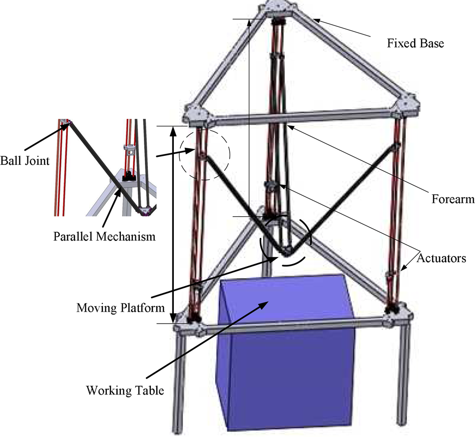
Robot architecture for the DELTA robot
Inverse and Forward Kinematics
A simple kinematic analysis suggests that a mechanism based on the parallel architecture can possess high accuracy and repeatability. This is because the end-effector motion is generated by actuated links directly connected to the base. The DELTA robot utilizes three parallelograms that allow the moving platform to remain at a fixed orientation with respect to the fixed base. A parallel kinematic architecture with the drives mounted to the base makes very high accelerations of the end-effector possible.
The kinematics may be solved as a forward or inverse task. The kinematics analysis is based on the geometry of the DELTA robot, which might be described as follows. The robot consists of a triangular moving platform and a fixed base (Fig. 2).

Geometric description of the DELTA robot
A static Cartesian coordinate frame XYZ is fixed at the centre of the base, to which a mobile Cartesian coordinate frame XYZ is assigned to the centre of the mobile platform. Pi, i=1, 2, 3, and Ci, i=1, 2, 3, are the joints located at the centre of the base (as presented in Fig. 2) and the moving-platform passive joints, respectively.
The coordinates of points Pi in the reference frame related to the fixed base plate are given by

where R is the radius of the fixed base's circle.
Similarly, the coordinates of points Ci in the reference frame related to the moving platform are given by
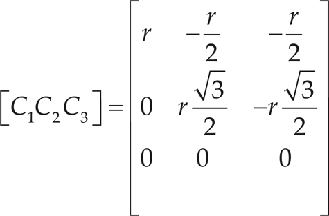
where r is the radius of the moving platform's circle.
Hence, the constraint equations for the DELTA robot are generated by applying Pythagoras’ rule in three dimensions to each pair of arms [4, 7]. Noting that L1 = L2 = L3, the equations define three spheres:
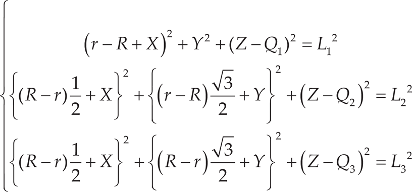
Therefore, Eq. (3) is used to establish the expression of the inverse kinematic model:

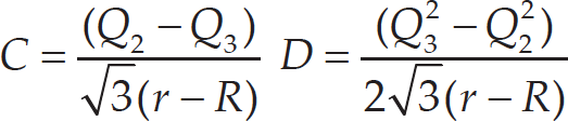
Alternatively, for the establishment of the direct kinematic model, we solve the system (3) with respect to X, Y, Z, which yields the following system:

where


In this subsection, the workspace of the proposed DELTA robot will be discussed in detail. For a robot in the context of industrial application and given parameters, it is important to analyse the area and the shape of its workspace. Calculation of the workspace and its boundaries with perfect precision is crucial, because they influence the dimensional design, the manipulator's positioning in the work environment and the robot's dexterity in executing tasks. The workspace is constrained by several conditions, mainly the boundary that is obtained through solving inverse kinematics. Moreover, the workspace is limited first by the accessibility of drives and joints, then by the occurrence of singularities and finally by the link and platform collisions.
Figure 3 depicts the task's definition and dimensions. Fig. 4 shows a dimension concept of the DELTA robot and depicts its workspace, the location of its world reference frame and the chief geometrical parameters of the workspace. Fig. 4 shows the location of the centre of the mechanical interface from the centre of the moving platform. Moreover, the angle 0 in Fig. 4 is restricted to between 30° and 80°. In order to generate a reachable workspace (1000 mm × 700 mm × 400 mm) for the proposed DELTA-robot system, a numerical algorithm was introduced. For the design of a DELTA robot, the kinematic parameters of the robot should be initially determined. The design parameters are determined for a desired workspace with the optimization techniques described in [13].

Workspace definition

DELTA-robot design concept
By analysing Eq. (4), we note that for each value of given Qi (Qi ∊ [Q
imin
Q
imax
]), the workspace of each kinematic chain is a sphere radius R, which is irregular in form. Obtaining a workspace of regular form is possible by forming a circle equation X2 + Y2 = r2 that is perpendicular to Z. The goal is to obtain the largest prescribed and regular dexterous workspace using the objective function
The system implementation will consist of three parts: mechanism and hardware development, kinematics and software development (Fig. 5).
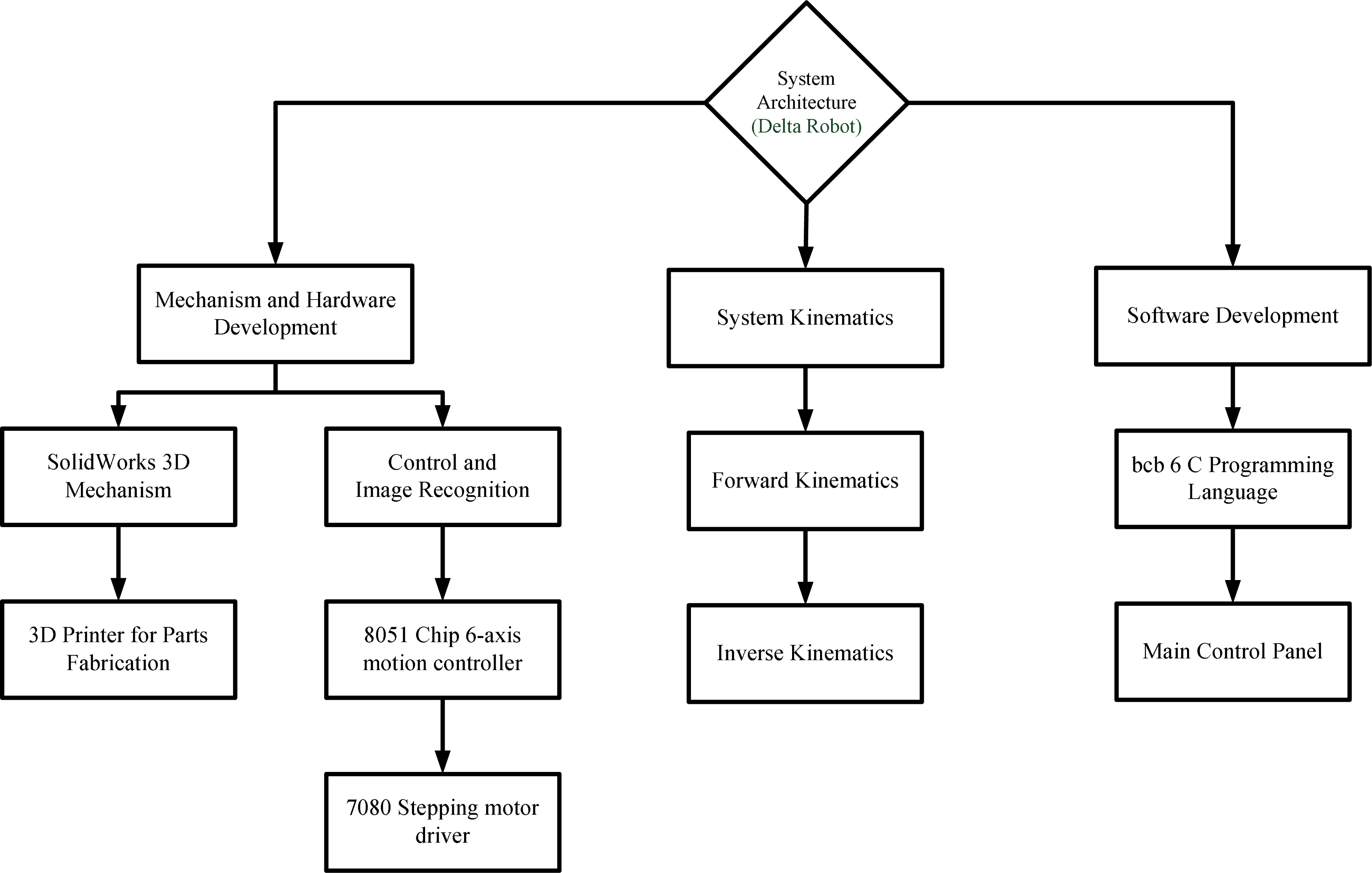
System implementation structure
The design of the proposed DELTA robot includes a two-axis rotation of the wrist, a gripper and a six-axis robotic arm. The proposed DELTA robot consists of a fixed base, a travelling plate and three kinematic chains that connect the fixed base to the travelling plate, which is the robot's end-effector. Each kinematic chain comprises an upper arm that is actuated by a revolute, brushless DC servomotor and a lower arm. Figure 6 displays the 3D-concept drawing and the constructed system.
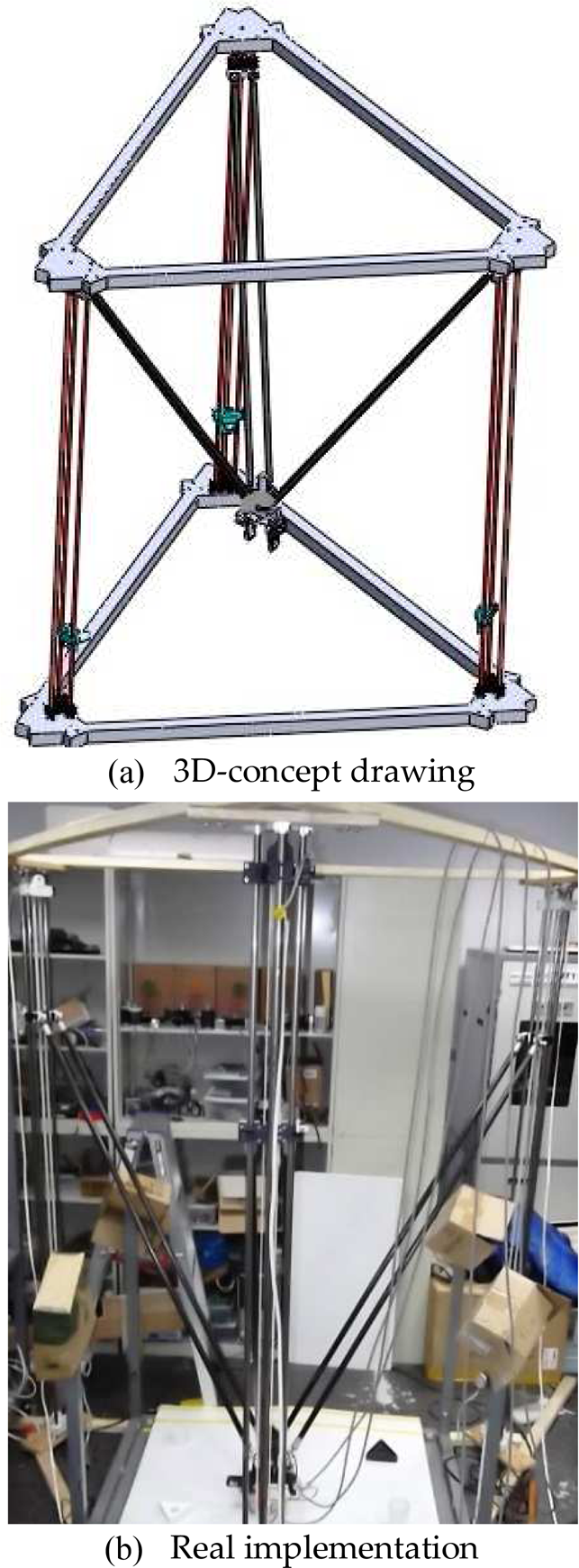
System implementation
To speed up the construction of the robot, 3D printing is utilized to fabricate the end-effector parts, which are designed in a modular fashion for ease of reconfiguration and assembly (Fig. 7). This method reduces the cost and tooling time by approximately 80% of those values achieved using Computerized Numerical Control (CNC) in the fabrication of parts.

printing in end-effector fabrication
A single six-axis control chip 8051 (Model: C8051F360) is used as the control board in this work. Such chips are used to connect Universal Asynchronous Receiver Transmitters (UART) to a control computer. A stepping motor driver (Model: 7080), manufactured by Applied Motion Products, is used to drive the forearm of the DELTA robot. Additionally, the Complementary Metal-Oxide Semiconductor (CMOS) video camera (Model: VMD-P310A) with 300 megapixels is used for image recognition.
Software Development
The software is composed of a standard programming-language compiler and a boot loader that executes functions on the microcontroller. The controller, including the control algorithm and the human-machine-interface (HMI), is coded in the Borland C++ Builder 6 Personal software environment. The software framework is part of the robotic assembly cell. For the positioning task, each coordinate of the input position is calculated, given the reference and measured positions of the robot. The input values for the task space are then converted to joint space using inverse kinematics and control is then applied to each axis of the robot.
Results and Discussion
Performance evaluation is important for optimal robot positioning within a workspace. To evaluate the performance of the developed DELTA robot, a measurement set-up is built. A repeatability test is carried out to ensure the accuracy of the robot system. The measurement set-up has nine points, each with assigned coordinates (Fig. 8). The proposed DELTA robot moves through the test points (points 1−9) 15 times, and estimates the coordinates of the points each time they are passed. Clearly, the measured coordinates of each point are very close to each other. The mean positioning error is small, approximately 2∼3 mm. The mean errors (mm) of the measurements of points 1−9 are (−2,3), (0,−2), (2,−2), (0,0), (0,0), (0,0), (2,−3), (−2,2) and (2,−2). This positioning accuracy is close to that of an equivalent commercial robot. These results reveal that the robot system is reliable.

Coordinates of the measured points for the repeatability test
The proposed robot system was entered into robotic competitions in Taiwan. Three tests that were carried out in those competitions are discussed below.
First, the pick-and-place operations in a domino test were used to verify the reliability of the DELTA-robot system. Pick-and-place operations involve a straight vertical motion at the pick-up location (from the starting point to the end point), followed by a straight horizontal motion and another straight vertical motion at the placement location. The path-planning process comprises searching for a motion that ensures the accomplishment of these assigned tasks. If the desired position of the end-effector is specified, then the corresponding angles of each of the three arms must be determined. This experiment focuses on point-to-point motions along specified paths. After the hardware is initialized, the DELTA robot is moved to a predefined position. Once it has obtained a coordinate of a work piece, the system starts path planning; it estimates a time when the DELTA robot can start the tracing process. Once the desired point coordinates have been determined, the operator can use inverse kinematics to calculate the control trajectory to be followed. The complete control trajectory is divided into various sections. Each domino is translated from a starting point to a target point. The reference point of the pick-and-place path coincides with each grid point to find the best position between the robot and the task.
To play the domino game, the symmetry of the domino's path was identified. Figure 9(a) displays the original locations of dominos. The thickness of each domino is 10 mm and the spacing between adjacent dominoes is 30 mm. The robot must pick up the dominos and place them in their assigned positions (from point “S” to point “E” in Figs. 9(b)–(c)). Figure 9(d) presents the real pathway of the dominos during the experiment. The location of the domino was associated with the path. Finally, all of the dominos were put in place after the DELTA robot had pushed over the first domino (Fig. 9(e)). Therefore, the experiment reveals the fact that the proposed controller can track the desired path. The proposed DELTA robot is intended to perform pick-and-place operations.

Domino test for the proposed DELTA robot
The second test was a writing and drawing test case to verify the reliability of the proposed DELTA robot. Figure 10 indicates the desired drawing path in the test. The drawing combines a Chinese character with a picture of a robot. The desired drawing in Fig. 10 was scanned and converted to point coordinates. Figure 11 presents the desired path among the grid points. On the basis of input workspace boundaries, environmental constraints and analysis of the resolution, the workspace was discretized into grid points whose coordinates are computed and numbered. Among all of the grid points, those that can feasibly become reference points are selected for that purpose. Figure 12 shows the robot's performance in the drawing and writing test, based on Fig. 11. The reliability test was conducted several times, and the corresponding task was completed with a 100% success rate. Accordingly, the proposed scheme can cause the DELTA robot to follow the pathway and move to the target even when creating a complex drawing.

Desired drawing
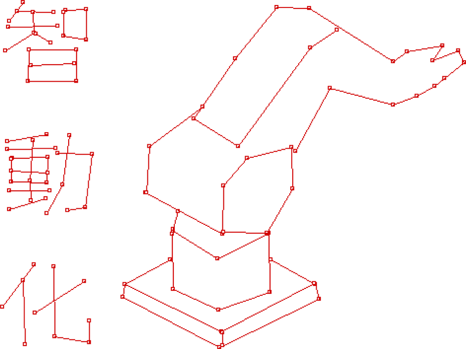
The desired drawing converted to a point-to-point picture
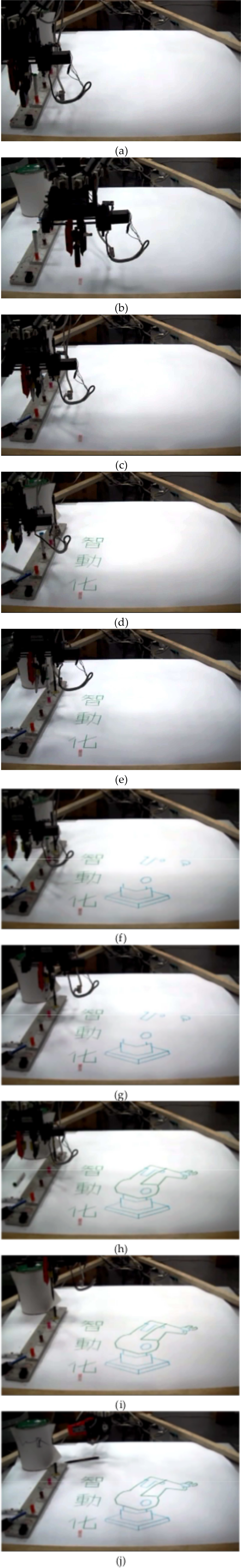
Writing and drawing test for the proposed DELTA robot
Case III is an image-recognition test. The robot must pick up a coloured ball and place it in a hole of the same colour. Figure 13 displays the flow chart for the image-recognition task. Figure 14 presents the actual pick-and-place performance of the proposed DELTA robot in this third test, and indicates that the robot effectively performed the pick-and-place task with the coloured balls. The robot safely avoided obstacles and reached the target hole. This test was performed many times, and the task was completed with an approximately 92% success rate. These experiments indicate that the DELTA robot tracked the object of the desired colour, and that the proposed system is effective owing to its advanced adaptability, stability and robustness.

Flow chart for image recognition

Experimental results for image-recognition test
This work introduces a novel design of a DELTA robot with an end-effector for performing multifunctional operations, and provides insight into the way this academic innovation has been transformed into a mechatronic kit for university education. The design of the proposed DELTA robot includes the two-axis rotation of the wrist, a gripper and a six-axis robotic arm. The robot system's implementation involves the development of the mechanism, both its hardware and software. The cost of implementing the whole of the proposed robot system is about US$1,000, which is only 10% of the cost of an equivalent commercial robot. Hence, the main advantages of the proposed system are that it is modular, reconfigurable and less costly than its alternatives. A repeatability test was performed to ensure the accuracy of the robot system. To evaluate the performance of the DELTA robot, various experimental scenarios were introduced. The results reveal that the proposed DELTA robot completes the tasks effectively. It is hoped that the proposed solutions to the problems that are discussed in this research are useful in the construction, automation and large-scale manufacture of parallel-link robot systems.