
Abstract
Maintaining stability is a significant challenge during the control of a robot astronaut while climbing with human-like dual-arm action in a space station. This challenge is caused by conflicting force generated by dynamic internal forces in the closed chain during dual-arm climbing. In general, an impedance controller is suitable for solving this problem. However, the conflicting force in the rigid closed chain is stored in the virtual spring of the impedance controller (especially in microgravity), where even small disturbances cause a significant change in robot astronaut movements. As such, it is difficult to select suitable control parameters for the stable climbing of a robot astronaut. This paper proposes an adaptive algorithm to optimize the impedance controller parameters. This eliminates conflicting force disturbances, with one arm in compliance with the motion of the other. It provides scope for achieving stable motion without the need for precise control parameters. Finally, the stability of the proposed algorithm is demonstrated by Lyapunov theory using a robot called ASTROBOT. The experimental results show the validity of the proposed algorithm.
Introduction
Space robots were developed to assist or replace astronauts for tasks in outer space. Space robots alleviate human astronaut workloads and can also reduce work-based risks in the international space station (ISS); furthermore, they are time-saving and economical [1, 2]. However, existing robots, such as Canada and SPDM [3, 4], cannot cover all extravehicular areas, especially at the base of the ISS, where the earth observation equipment is located. Therefore, significant research and development have gone into producing human-like robot astronauts, such as Robonaut2 [5] and DLR Justin [6].
The dynamics and control methods of a robot astronaut are significantly different from an earth-based robot [7]. Also, due to microgravity and narrow room in the space station, uncertain dynamic interactions and collision forces are serious threats to control stability, where even small disturbances may lead to significant movement changes.
This makes robot astronaut dynamics very complex, with stable movement difficult to maintain. Furthermore, the moving modes of a robot astronaut are no longer solely based on biped dynamics; they now involve dual arms to climb or even glide (including rolling and reversing) by using ergonomic handrails in the space station (Fig. 1). Therefore, control methods for earth-based robots cannot be directly used in the control of space-based robots.

Motion model of climbing astronaut
Dual-arm coordinated locomotion control approaches can be classified as hybrid position/force control and impedance control. Raibert and Craig (1980) [8] formulated the hybrid position/force control method for interactive tasks between a mechanical arm and the environment; this included such tasks as peg-in-hole assembly and wiping glass. Uchiyama et al. (1988) [9] extended hybrid position/ force control to the coordination of two robots, which performed well on the coordinated control scheme. However, this approach required a real-time switch control mode in accordance with the selection matrix, which may cause disturbances in the robot astronaut system. Furthermore, it reduced the robustness of the system under microgravity conditions.
In order to maintain stability against external environment disturbances and overcome force/position hybrid control method defects, Hogan (1985) [10] applied impedance control to the robot control, which established an expected dynamic constraint relationship between the manipulator and the environment. Schneider and Cannon (1992) [11] proposed a dual-arm cooperative theory based on object impedance control, where the desired impedance was aimed at the object itself, rather than on the end effector. Platt (2011) [12] employed an extension of multi-priority impedance control for a controller, where the first-priority impedance was defined at the end effector in the Cartesian space and the second-priority impedance was defined in the joint space [13]. NASA applied this method to their Robonaut2 simulation. Typically, the impedance controller, which is mentioned above, is used for docking with peg and hole [14], assembly [15] and moving objects [16]. Besides, a variety of control techniques has been developed for flexible manipulators [24], linear motor with high-frequency dynamics [25] and space robots for capturing a non-cooperative target [26–28].
In addition to the impedance controller tasks mentioned above, conflicting forces exist in the rigid closed chain of the robot astronaut, where its arms are required to correct deviations while climbing. As a result, the deformation of the virtual spring is significant (approximately 30 mm), which means that the spring stiffness has to be small in order to limit the conflicting force in the closed chain. However, small spring stiffness is vulnerable to instability. Also, the dynamics of a robot astronaut are very different and more complex compared to an earth-based robot.
This paper proposes an adaptive impedance controller to adaptively adjust the impedance parameters based on a forgetting factor function. This strategy includes a different control method for each arm. In order to ensure stability of the robot astronaut, position control was adopted in the master arm and the proposed adaptive impedance controller was adopted in the control of the slave arm. This reduced (and even eliminated) the conflicting force, thereby correcting the moving deviations by adaptively changing the static equilibrium position of the virtual spring.
Section 2 presents the development of a multipoint impact dynamics model and also derives force optimization for the robot astronaut. Section 3 presents an analysis of the conflicting force, as well as introduces the master-slave arm selection method. Section 4 proposes a novel, improved impendence control method based on a forgetting factor function, along with demonstrating the stability of the system under the Lyapunov stability theorem. The last section presents the experimental results, which validate the proposed approach, with the final concluding remarks presented prudently.
When climbing in narrow or cluttered spaces (common in a space station), impact regularly occurs when the robot astronaut makes contact (including multipoint impact) with its environment. Due to microgravity, the forces generated upon impact greatly influence the robot; therefore, a multipoint impact dynamics model was established as the basis for the stable control of a robot astronaut in a space station. Furthermore, where two or more contacts occur when climbing, the optimization provided a solution for obtaining the force distribution during impact.

Multipoint impact model for robot astronaut
The Newton-Euler method established the multipoint impact dynamics model for the robot astronaut through kinematical constraint (Fig. 2). Assuming that the robot astronaut has n contact points with the station, the kinematic constraints are imposed as:

The dynamical equation for the robot astronaut in microgravity is:

where q is the joint angle, M (q) is the inertial matrix in the joint space,
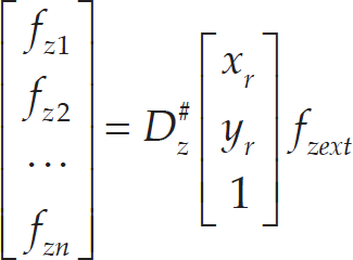
f zext is defined as the desired resultant external force; it is the vector sum of all the contact forces.

Force optimization is used to simplify the influence of contact impact. According to the dynamic model, the resultant force on the z-axis direction is:

set

So, the optimization formula can be written as:
where
During the climbing process, the robot arms form a rigid closed chain and affect each other through the body. Here, a small error may lead to a significant waggle or even a tilt (Fig. 3).

During the climbing process, the robot arms form a rigid closed chain and affect each other through the body. Here, a small error may lead to a significant waggle or even a tilt.
The control of a robot climbing in a space station is complicated due to the holding errors and closed chain system. There are various kinds of holding error that can occur because of the unexpected multipoint impacts, mechanism deformation and vision errors (Fig. 4). In addition, the closed chain formed by the two arms should be treated as a combination of subsystems given that errors in the closed chain cause an unexpected internal force and intensify instability. In this section, on the basis of the conflicting force analysis, the two arms are defined as the master and slave arms.

Grasping state
The force analysis was developed on forces between the arms and handrails because there were only two six-axis force/torque sensors installed at the end of the arms. The forces acting on the shoulders were decomposed into two parts: parallel to climbing direction and perpendicular to climbing direction (Fig. 5).
The robot astronaut was designed to move in the XOY plane; as such, forces were projected onto the XOY plane. The force analysis is shown below:

Robot statics analysis
Forces acting on the shoulders can be derived from the contact force and torques using a statics analysis [23]. Forces and torques passing from the i+1th joint to the ith joint are:


where f i is the force linkage i+1 acting on linkage I, while n i is the torque linkage i+1 acting on linkage i.
The applied force of shoulder A (F A ) is derived and projected onto the XOY plane; it is then decomposed into perpendicular and parallel forces.


Similarly, the applied force of shoulder B (F B ) is decomposed as follows:


The arm with the larger internal force needs to be adjusted because it causes a conflicting force in the closed chain. As a result, the arm with the larger perpendicular force is defined as the slave arm, while the other is defined as the master arm. Comparing FA// with FB// : if FA//<FB//, then arm A is the master and arm B is the slave; if FA//>FB//, then arm B is the master and arm A is the slave. Different control strategies were used for arms A and B (see Section 4).
In Section 2, the expected forces and torques exerted on the robot body were calculated using force optimization. In Section 3, the master and slave arms were defined with conflicting force analysis. In this section, an adaptive algorithm is proposed to optimize the parameters of the impedance controller, which can reduce (and even eliminate) conflicting force disturbances in the slave arm.
Master-slave adaptive impedance controller
The slave arm changed the equilibrium position of the virtual spring (Fig. 6) corresponding to the main arm motion in order to prevent the robot astronaut from shaking. It correctly adjusted the robot position and orientation, then released the conflict force.

The controller policy for master slave coordination
When the robot holds the handrails, the desired pose of the robot involves two arms that are symmetrical to each other. Eventually, arms in such a motion posture will move stably. As is shown in Fig. 6, the green line is the desired symmetric line. Due to the errors, such as unexpected multipoint impacts, mechanism deformation and vision errors, however, the robot is often asymmetric and the centre line of the robot is deviated (red line in Fig. 6). As a result, there will be an internal force in the virtual spring of the impedance controller, which is generated from the distance between the red line and the green line. The internal force is the source of conflicting force in the closed chain. To solve this problem, the master arm's path-planning strategy is to control the robot towards the expected symmetrical pose. Meanwhile, the slave arm gradually adjusts the equilibrium position of the virtual spring in the impedance control by the forgetting factor function in order to eliminate conflicting force under the precondition of the stably moving robot.

Adaptive impedance control law
The configuration of both arms was symmetrical, while their rigid damping coefficients were the same; hence, the impedance equation of both arms can be written as:

where

where 7f7 and 7n7 are derived from Eqs. (7) and (8), respectively.
For impedance control, Eq. (13) was derived in six directions: three position directions and three angle directions. In order to simplify the calculation, the following analysis addresses only one direction (as the other five directions are identical to it).
Set e as the error between the equilibrium position,

Set ΔF as the difference between the expected contact force., F des , and the actual contact force, F ext :

Now, the impedance equation can be changed to:

The spring damping system should operate in the critical damping state:


In order to simplify the equation, it may be defined as:

Now Eq. (19) can be written as:

The classical impedance control method for robot climbing (as described above) has a large conflicting force stored in the closed chain. Hence, the classical impedance controller cannot eliminate the inherent internal force. Inspired by the astronaut climbing process, the following subsection proposes an improved method based of impedance control.
This paper introduces a forgetting factor function [17–19] into the impedance controller; see Eq. (22). When the robot astronaut is climbing, the virtual spring position can be adjusted to the expected motion state in the impedance controller using the provided forgetting factor function. This can eliminate the conflicting force in the rigid closed chain when the slave arm is controlled using the proposed impedance controller in order to follow the motion of the master arm.

where r(n) ∈ [0, 1) describes the forgetting factor function, n is the amount of iterations and e n (t) is the deviation of the controlled variable.
Based on the forgetting factor function, Eq. (13), which describes the slave arm impedance control, can be written as:

As per the previous section, the following analysis only addresses one direction. Here,

where

where

where

The forgetting factor function, r(n) ∈ [0, 1] is a monotone decreasing function in the climbing period. At first, r(n) is closed to 1, so the equilibrium position of the virtual spring is nearer to the expected position of the slave. Then, r(n) decreasingly approaches 0 and the equilibrium position approaches the position corresponding to the master arm. When the climbing ceases, the master arm determines the equilibrium position.
The forgetting factor function is written as:

As a result, the acceleration change of the slave arm
Lyapunov's direct method is a reliable and robust tool for system stability analysis [20]. From an energy perspective, it is used for determining the stability of a system's equilibrium state by the Lyapunov function, V(x). The stability criterion shows that the key of Lyapunov's direct method is finding the function V(x).
Due to special compliance control for robotic dual-arm climbing the Lyapunov function is selected in the error space:

where the matrices


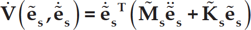
The time derivative of the Lyapunov function is:

It can be converted to:
Next, based on Eq. (23), the following equation is obtained:

By substituting Eq. (34) with Eq. (33), the following equation is obtained:

As
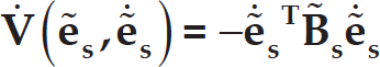
where
System description of a robot astronaut
In order to simulate an astronaut climbing in a space station, a humanoid space robot system named “ASTRO-BOT” was developed. The robot astronaut consisted of a head, two arms and a body (Fig. 8). A binocular stereo vision system was built into the head in order to obtain position information. There were two end effectors at the end of each arm.

ASTROBOT system
Gravity compensation equipment is necessary for motion research involving space robots. Various schemes have been employed to compensate for gravity on earth, including air flotation, hanging wire and buoyancy methods [21]. However, these methods are expensive and complex. The air flotation method can only accommodate testing in two dimensions. The hanging wire method is complex and has difficulty achieving real-time control. The buoyancy method needs to seal the robot, while there is also a factor in water tension during testing. Therefore, this paper proposes a passive mechanism to simulate a microgravity environment for the ASTROBOT research [22]. The mechanism comprises three main parts: a horizontal tuning mechanism, a motion mechanism and a gravity compensation mechanism (Fig. 9).

Microgravity simulation system: ① to ⑥ horizontal tuning mechanism; ⑦ to ⑧ motion mechanism; ⑨ handrail; and ⑩ gravity-compensation mechanism.
At the climb commencement, the actual speed of a robot is V
A
, the detecting speed is V
C
and the speed error is V
B
; hence, the relationship between them is

Initial motion status of ASTROBOT
Table 1 lists the basic information of each joint.
Joint base parameters

Figure 11 shows that, where the robot was only controlled in position, some of the joint driven torques were too large for the motors. Therefore, the position controller could not be used to complete climbing.

Joint torque in position control
Based on practical situations and experience, the total control time was set to 5 s and the control cycle was set to 0.001 s. Table 2 lists the other control parameters.
The damping factor was
Decoupling control parameters

After experimental analysis, arm A was selected as the main arm and arm B as the slave arm. The experimental results and analysis are provided below.
Climbing position status
In order to demonstrate the effectiveness of the adaptive impedance controller for slave arm compliance with master arm motion, some of the experimental tracking data were plotted, showing the trajectory error of the x, y coordinates (Δx, Δy) (Figs. 12 and 13). Moving errors in Fig. 12 are caused by the robot using classical impedance control. When the robot's two end effectors hold handrails, they form a closed chain, such that even small distractions (unexpected multipoint impacts, mechanism deformation and vision errors) can cause a big moving error. In the last stage of climbing, the robot body kept shaking, with the shaking curve showing divergence trends. This means that it was difficult to keep stable. In Fig. 13, the moving error curves become flat after the climbing finished because the robot is controlled by the adaptive impedance control method. By this method, the conflicting force is eliminated and the robot body becomes stable.

Moving error of robot body using classical impedance control

Moving error of robot body using adaptive impedance control
Figs. 14 and 15 show the joint output torques of robots' arm using classical impedance control. Figs. 16 and 17 show the torques of arms using adaptive impedance control. At the beginning, the torques in Figs. 14 and 15 are similar to torques in Figs. 16 and 17. In the later stage, the fluctuation in the classical method's diagrams becomes bigger and bigger in Figs. 14 and 15. However, the joint torques in Figs. 16 and 17 respond to a reasonable extent and finally fall within a normal range using the adaptive controller.
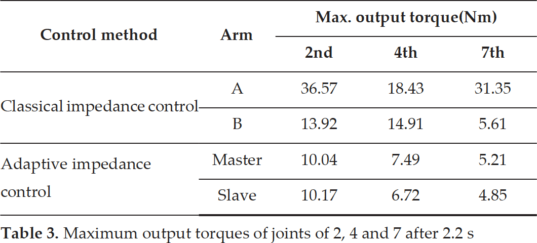
In this experiment, the joints of 2, 4 and 7 have maximum output torques. Table 3 lists their maximum values (excluding torques in the initial period). From the table, we can see that the joint output force torques' maximum values in relation to the adaptive method were much smaller than the maximum values for the classical method. This shows that the adaptive impedance control method is able to prevent joint damage and robot shaking when climbing.
Maximum output torques of joints of 2, 4 and 7 after 2.2 s
Maximum output torques of joints of 2, 4 and 7 after 2.2 s

Joint output torques of arm A using classical impedance control

Joint output torques of arm B using classical impedance control

Joint output torques of master arm A using adaptive impedance control

Joint output torques of slave arm B using adaptive impedance control
Due to errors, such as unexpected multipoint impacts, joint positioning errors and vision inaccuracy, the robot deviates in terms of both pose and position from the desired ones. These deviations cause a conflicting force in the rigid closed chain formed by two arms, which may lead to big force/ torque between the end effector and the handrail, as well as damage the joints. As is shown in Figs. 18 to 21, the forces and torques between two arms and handrails controlled by the classical impedance control method started fluctuating in the final stage and showed a trend of amplification in the end. To overcome this problem, an adaptive algorithm to eliminate the conflicting force during the motion of one arm, in compliance with the other one, is proposed. It is based on the impedance control and forgetting factor function, which are applied in order to adjust the virtual spring. As is shown in Figs. 22 to 25, the contact forces and torques of two arms, controlled using the adaptive impedance controller, started fluctuating and were alleviated in the end. Table 4 lists the maximum contact forces under the control of each of the two different methods. Obviously, the contact forces and torques of the arms controlled using the classical method are much bigger than their counterparts when using the adaptive method. These show that the adaptive impedance controller that we proposed can reduce the connecting force/torque between the end effector and the handrail, as well as eliminate the conflicting force in a rigid closed chain.

Contact force of arm A using classical control

Contact torque of arm A using classical control
Contact force/torque


Contact force of arm B using classical control

Contact torque of arm B using classical control

Contact force of master arm A using adaptive impedance control

Contact torque of master arm A using adaptive impedance control

Contact force of slave arm B using adaptive impedance control

Contact torque of slave arm B using adaptive impedance control
This paper proposed a feasible impedance controller with a forgetting factor function for a robot astronaut to climb stably in a space station. It also defined the master and slave arms of a dual-arm robot based on the kinematics and multipoint dynamics of a robot astronaut. The master arm moved with a path-planning algorithm based on a position controller, while the slave arm was compliant with the motion of the master arm when using the proposed impedance controller. This eliminated the conflicting force disturbance in the closed chain during the dual-arm robot astronaut's climbing tasks, ensuring good stability. Comparison experiments were conducted using ASTROBOT; the following conclusions were reached:
During ASTROBOT climbing, it was difficult for the robot astronaut to stably move with just the position controller in both arms. Here, undesired trajectory movement occurred (and even caused damage to the joints). When the classical impedance controller was used, there were large conflict forces between the end effecters and the handrails. The maximum joint output torques of the two arms were 36.57 Nm and 14.91 Nm; the maximum contact force/torque was 145.22 N/49.47 Nm.
The proposed control strategy with the impedance controller, based on the forgetting factor function, achieved better results. The slave arm was sufficiently compliant with the master arm motion, eliminating the conflicting force disturbance during the dual-arm robot astronaut's climbing tasks, resulting in good stability. The output torques of the joints decreased, while the contact force/torque between the arms and handrails tended to 0 at the end of the movement. The maximum output torques of the joints in the two arms were 10.04 Nm and 10.17 Nm; the maximum contact force/torque was 92.67 N/31.81 Nm.
Although the present paper only focused on the dual-arm effect during climbing, legs also play an important role in astronaut-moving, such as boosting, turning or even anchoring. Besides, gasping analysis is also critical in robot astronaut control. In our future work, we will develop a new control strategy and an experimental system to evaluate the performance of a robot astronaut moving in the ISS within a microgravity environment.
Conflict of Interest
The authors declare no known conflict of interest regarding the publication of this paper.
Footnotes
Acknowledgements
The authors wish to express their gratitude to National High Technology Research of China (grants 2015AA043101 and 2015BAF10B02), Basic Scientific Research (grant B2220133017), and the National Natural Science Foundation of China (grants 61503029, 61573063 and 61305112) for their support of this work.