
Abstract
Dual-arm robot astronaut has more general and dexterous operation ability than single-arm robot, and it can interact with astronaut more friendly. The robot will inevitably use both arms to grasp payloads and transfer them. The force control of the arms in closed chains is an important problem. In this article, the coordinated kinematic and dynamic equations of the dual-arm astronaut are established by considering the closed-chain constraint relationship. Two compliance control methods for dual-arm astronaut coordinated payload manipulating are proposed. The first method is called master–slave force control and the second is the shared force control. For the former, the desired path and operational force of the master arm should be given in advance and that of slave arm are calculated from the dual-arm robot closed-chain constraint equation. In the share control mode, the desired path and end operational force of dual arms are decomposed from the dual-arm robot closed-chain constraint equation directly and equally. Finally, the two control algorithms are verified by simulation. The results of analysis of variance of the simulation data show that the two control methods have no obvious difference in the accuracy of force control but the second control method has a higher position control accuracy, and this proves that the master–slave mode is better for tasks with explicit force distribution requirements and the shared force control is especially suitable for a high-precision requirement.
Introduction
Because the space robot can assist the astronaut to do on-orbit tasks, reduce astronaut extra-vehicular activity (EVA) time, and reduce the safety risks brought by the space environment to astronaut, 1 the international space station is equipped with multiple space robots, such as the Space Station Remote Manipulator System (SSRMS), 2 the Special Purpose Dexterous Manipulator 3 and the Japanese Experiment Module Remote Manipulator System. 4 Similar to the international space station, the Chinese space station currently plans to deploy a robotic manipulator system Chinese SSRMS (CSSRMS), and the CSSRMS consists of core module manipulator (CMM) and experimental module manipulator (EMM). The length of CMM and EMM is about 10 and 5 m, respectively, and the maximum load is 25,000 and 3000 kg, respectively. The CMM and EMM can work independently or together to complete the maintenance of the Chinese space station. 5 The main tasks of CMM include space station cabin transfer and docking assistance, hovering spacecraft capture and docking assistance, astronaut EVA support, etc. EMM’s main tasks include exposed load care for experimental platforms, astronaut EVA support, and small load transfer. 6 With the development of China’s manned space engineering mission to a higher stage, higher requirements have been put forward for space manipulation capability. Compared with a single-arm space robot, a multiarm robotic system has much more dexterity and flexibility and is capable of completing more complex tasks. 7 Especially, the humanoid robot astronaut has arms like human beings and has the unique advantages of a wide range of applications, strong collaboration ability, high reliability, and ability extension, which can serve the astronaut better. 8 In recent years, NASA’s astronaut Robonaut 2 and Japanese robot astronaut KIROBO have launched into the international space station to serve the astronaut. 9,10 Robonaut 2 is a dual-arm humanoid robot with seven degrees of freedom (DOFs) in each of its arms, and a five-finger dexterous hand with 12 DOFs is installed at the end of the arm. It can use a variety of astronaut tools for dual-arm collaborative and dexterous operation in space. Scientists at Russia’s Gagarin cosmonaut training center have also developed their humanoid robotic astronaut sar-401, whose hands can perform delicate tasks such as ball handling, opening, and closing as well as lift a 10-kg load in gravity. 11 Therefore, it is essential to develop a robot astronaut for the Chinese space station, and the robot has a general and dexterous operation ability, also can interact with astronaut more friendly. 12
Different from the single-arm robot, the robot astronaut will inevitably use both arms to grasp the load and transfer it. Under this condition, the double arms and the load form a closed-chain movement mechanism, and the two arms keep contact with the load during the movement. To solve the above problem, the coordination of kinematics and dynamics of dual-arm robot should be considered. Kinematic coordination means that both arms must move synchronously to track the desired pose of the load. The coordination of dynamics refers to the robot arm needs to control the force/torque (F/T) produced by the two-arm robot system in a specific way. The state of art of related issues in the field of dual-arm robots have been summarized in ref., 13 and it also points out that the further research directions will incorporate more visual feedback and cognitive capabilities based on artificial intelligence. Many researchers have studied the decomposition of F/T and pose in the case of a closed chain. For example, Tianliang Liu presents position-level, velocity-level, and acceleration-level resolved motion control methods of dual-arm manipulators with closed chain, and a dynamic modeling and simulation platform has been established. The resolved motion control methods are verified through a typical case simulation, but the article does not study the force compliance control method for the two-arm coordination. 14 Xu divides the differential motion equation solve the problem of a dual-arm space robot on floating base into two subspaces with few degrees and make it more convenient to solve the desired joint velocity of both arms to realize the dual-arm coordinated capture control. 15 Erhart and Hirche deduced the analytical expression of nonsqueezing load distribution, and the research results is more suitable to be applied to internal force calculation and grip force optimization in multifinger manipulation. 16 In terms of force/position control in closed-chain operation, there are mainly force position hybrid control and impedance control. Yoshikawa introduced the hybrid force/position control method into the coordination control of a dual-arm robot, which can control the force and position of dual-arm robot well. However, in the control process, this method needs to switch the control mode in real time according to the selection matrix, which needs to improve the control stability and anti-interference ability. 17 Ren et al. proposed a dual-arm cooperative adaptive hybrid position/force control strategy based on Lyapunov stability analysis. This control strategy combines the self-convergence parameter estimation and contact force estimation of the center of mass of the object to be grasped, and it can achieve both internal force and contact force tracking at the same time. 18 To make the robot have good flexibility and overcome the defect of the force/position hybrid control method, the impedance control method is introduced into the robot arm force control. The impedance-based coordinated operation control method improves the flexibility, operational reliability, and computational efficiency of dual-arm robot system. 19 Platt proposed a dual-arm impedance control method for NASA’s robotic astronaut R2, since the arm of the robotic astronaut is a seven-DOF redundant robotic arm, so multipriority impedance control is considered in this article, where the joint space impedance operates in the null space of first-priority Cartesian impedance. 20
In this article, the mechanical system of the dual-arm robot astronaut is briefly introduced in the second section. The third section introduces the forward and inverse kinematics model of anthropomorphic seven-DOF arm and its dynamics with interaction force. In the fourth section, the model of the dual-arm robot with closed chain is established, which can be used to decompose the pose and force of the payload handled by dual-arm robot. In the fifth section, two coordinated force control methods, namely master–slave force control and shared force control methods used for dual-arm coordinated compliance control are introduced in detail. In the sixth section, a joint simulation model of dynamics and control algorithm for dual-arm robot astronaut to coordinate load handling is established, and simulation verification of the above two control methods is carried out. The last section gives the conclusion. The main contributions of this article are (1) the closed-chain kinematics and dynamics theoretical model of the dual seven-DOF arm robot astronaut is established to decompose the robot arm’s end pose and force command, and two control modes are provided according to the different decomposition methods of payload, that is, master–slave force control and shared force control. (2) A fully parametric dual-arm coordinated force control simulation framework is designed, which can be applied to other dual-arm coordinated control simulation scenarios.
Mechanism of the dual-arm robot astronaut
As shown in Figure 1(a), the robot astronaut’s configuration is similar with humans, and it is composed of two 7-DOF arms, a pair of 12-DOF dexterous hands, 3-DOF neck, a head as sensors platform, body (with a center processor inside), battery, and the CSSRMS grasp adaptor. The size of robot’s upper body is similar with an astronaut wearing spacesuit, which is convenient for the robot to share astronaut’ workspace and tools.

Mechanism of the dual-arm robot astronaut: (a) configuration of robot’s upper body, (b) anthropomorphic robotic arm of the robot astronaut, and (c) the five-finger dexterous hand.
As shown in Figure 1(b), the robot astronaut arm includes seven joints, and they are shoulder pitch, shoulder yaw, shoulder roll, elbow pitch, elbow roll, wrist pitch, and wrist yaw. Among them, shoulder and elbow joints are all modular joints with electromechanical integration design. Rated torque of shoulder pitch, shoulder yaw, and shoulder roll joints are designed to be 60 Nm, while rated torque of elbow pitch and roll joints are designed to be 40 Nm. The dual-arm robot astronaut developed in this article is designed by ourselves. Because it is a ground prototype, all components are commercial grade. To simplify the transmission mechanism, the joint just uses one lightweight current switch device (CSD) series harmonic reducer with a large-center hole. The harmonic reducer used in the shoulder joint is CSD-20-120-2UF of Harmonic Drive Company, and the CSD-25-120-2UF is used in the elbow joint. A permanent magnet synchronous motor, which has a high rated torque and low rated speed, is used, and there is also a speed sensor integrated in the motor. The shoulder joint uses Robodrive’s ILM50, and the elbow joint uses ILM38 motor. These two motors are from a German company named TQ group. To ensure man-machine safety, there is a power-off brake in the joint and the power-off brake is braking in emergency situations, which is from KEB Company China Branch. For safety reasons, a mechanical limit and an electrical safety limit are designed in the joint. A magnet resolver is integrated to measure the absolute position of the joint’s output axis. AksIM-2 off-axis rotary absolute encoder (053 series for elbow joints and 080 series for shoulder joints) is used here, and these encoders are from Renishaw, a British company. The six-dimensional F/T sensor between the elbow roll joint and the five-finger hand uses ATI industrial automation company’s MINI45, and the company is from United States. At last, a controller PCB, which can control the joint’s speed, position, and torque, is installed in the joint.
The five-finger dexterous hand is connected with the elbow roll joint, which consists of five fingers, a palm, a wrist joint, and a forearm (Figure 1(c)). The wrist joint has two DOFs: pitch and yaw, and they are driven by two linear drivers actuated by a gear motor and screw nut. To ensure the safety of the robot in contact with the environment, a six-dimensional F/T sensor is installed between the elbow roll joint and the five-finger hand, and it will be used for compliance control.
Modeling of the anthropomorphic seven-DOF arm
Forward kinematics
To get the forward kinematics of the robot arm, the D-H coordinate systems are designed as shown in Figure 2, and corresponding parameters are in Table 1.

D-H coordinate system of the anthropomorphic seven-DOF arm using the modified D-H coordinate system establishment method. D-H: Denavit–Hartenberg; DOF: degree of freedom.
D-H parameters of the anthropomorphic seven-DOF arm.

DOF: degree of freedom; D-H: Denavit–Hartenberg.
Based on the Denavit–Hartenberg (D-H) coordinate system, the homogeneous transformation matrix

where
The pose (orientation and position) of the last frame (the seventh frame 7) with respect to the base frame (frame 0) can be expressed as follows
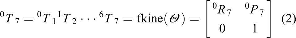
where
Inverse kinematics
To control the motion of the robot arm, the arm’s joint angles

According to the design of the robot astronaut, its arm’s first three joints (shoulder pitch, yaw, and roll) intersect at one point, forming a sphere joint. The last three joint (elbow roll, wrist pitch, and yaw) axes also intersect at one point to form a sphere joint. In addition, there is another revolute joint at the elbow. This configuration is called the S-R-S (spherical–revolute–spherical) configuration, which is similar with humans.
In contrast to a six-DOF manipulator, the arm in this article has infinite configurations for a given end pose. Therefore, a parameter must be defined to describe the redundancy. The arm angle proposed by Kreutz–Delgado is a better parameter for describing the self-motion of a generic anthropomorphic manipulator.
21
Suppose that the three shoulder and wrist joints intersect at points

Definition of the arm angle used to describe the redundancy of the 7-DOF manipulator. DOF: degree of freedom.
Dynamics with interaction force
Assuming that dual arms and the base do not produce the simultaneous motion, each arm of dual-arm robot astronaut can be approximate to the manipulator which is fixed on the base. Therefore, we can have the dynamic equation of each arm as follows

where Mk (k = l or r, l is for left arm and r is for right arm) is the mass/inertia matrix; the first term in equation (4) represents the inertial forces due to acceleration of the joints; the second term (Ck ) represents the Coriolis and centrifugal forces; the third term (Gk ) is the gravity; fek andτek are the contact forces and torques; and τk is the joint driven torques of arm-k.
Modelling of the dual-arm robot with closed chain
Dual-arm pose decomposition
Before dual-arm pose decomposition, the coordinate system of dual-arm robot with load is established firstly and then the force analysis of the load is carried out, as shown in Figure 4.
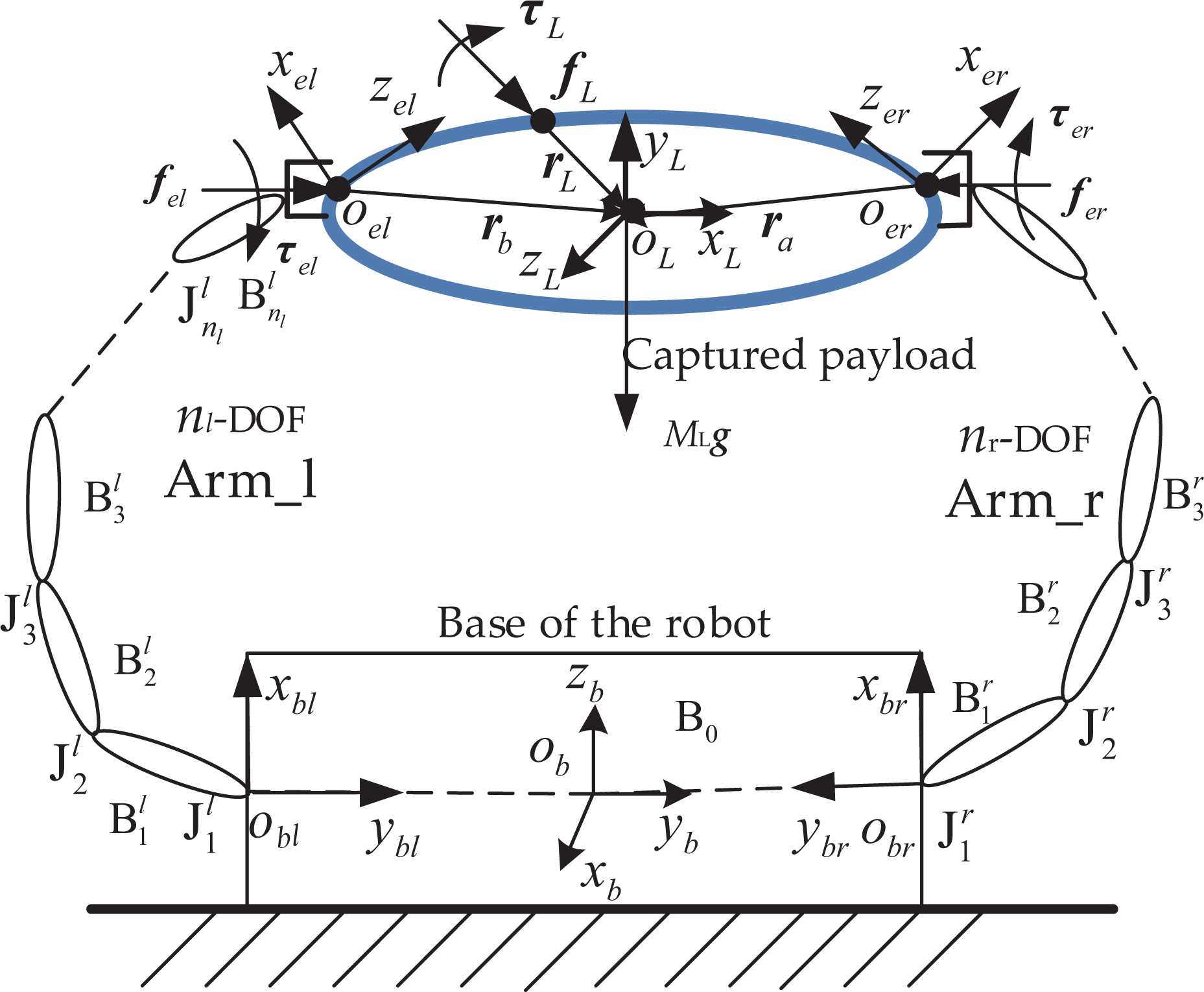
Force analysis and coordinate system definition of the robot astronaut’s two-arm coordinated grasping.
In Figure 4, ob _xb _yb _zb is the base coordinate system of the dual-arm robot astronaut. obl _xbl _ybl _zbl is the left arm base coordinate system and obr _xbr _ybr _zbr is the right arm base coordinate system. oel _xel _yel _zel is the left arm end coordinate system and oer _xer _yer _zer is the right arm end coordinate system. oL _xL _yL _zL is the payload centroid coordinate system. fL and τL are the external force and moment imposed by the environment. fel , τel , fer , and τer are the force and torque applied to the load of the left arm and the right arm, respectively. rL , rl , and rr are the vectors of the action point of fL , fel , and fer to the load centroid. vL and ωL are the line and angular velocity of the load centroid. ML , IL , and GL are mass, inertia moment, and gravity of the load.
From the kinematic relation in Figure 4, the following equation can be gotten

where k = l or r. l is for left arm and r is for right arm.

where
Combining equations (6) and (3), the joint angles of the robot astronaut’s arm can be solved by using the inverse kinematics.
Dual-arm F/T decomposition
When performing load transporting by two-arm cooperation, the F/T on the target load is shown in Figure 4. The key point of dual-arm force coordinated control is how to decompose the centroid force and moment to the end of the two arms. From the force relation in the graph, the force balance equation on the load can be as follows

In the same way, the equation of moment balance can be obtained

Combining (8) and (9), the following result is obtained

where,
The upper equation shows the relationship between the joint position, velocity, acceleration, end F/T of each manipulator, and the environment F/T. Equation (10) can be gotten by moving the load correlation section to the right of equation (9)
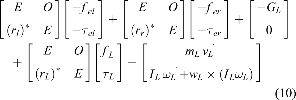
Equation (10) is the force analysis equation of the load, which will be used to control the dual-arm coordination F/T. Equation (11) is abbreviated as the following

where Fel
, Fer
, and FL
are the generalized force applied to the end of the left arm, the end of the right arm, and the load by the environment.

Coordinated force control algorithm
A general dual-arm coordinated compliance control strategy for dual-arm operation task is presented in Figure 5. Wherein, the inputs are the desired path and generalized force of the objective load by task planning firstly. Then the desired pose and operational force of end-effector of each arm are calculated from the coordinated pose decomposition and the coordinated force decomposition. Each manipulator completes the resolution of the task command by single-arm impedance controller. The corresponding joint angles of the manipulator are computed at the same time by inverse kinematics.

The flowchart of dual-arm coordinated compliance control.
In equation (11), FL
,
In master–slave force control mode, we define the master arm and the slave arm of dual-arm robot system according to the requirement of the operational task or the load capacity of the arm. Master arm is responsible for generating active motion, and the slave arm follows the main arm motion. Given the desired operational F/T of the master arm, the path of the load and its contact F/T with the environment are given in advance according to the mission requirements, so the desired path and operational F/T of slave arm can be computed from the closed-chain pose decomposition equation (6) and the load force decomposition equation (11). Then dual-arm coordinated operation is completed through the independent single-arm complaint controller.
In shared force control mode, the desired path and operational force of the end-effector of each arm can be directly resolved from the closed-chain constrained equation and the load force equilibrium equation. The control effect of dual arms reaches comprehensive optimization. The control process is defined as the shared force control strategy of dual-arm coordinated operation.
Master–slave force control
In master–slave force control mode, the expected F/T at the end of the main arm is given directly according to the task. If the left arm is the main arm, then the desired force vector can be given as shown in the following equation

By substituting (13) into (11), the desired force and moment at the end of the slave arm can be obtained

Shared force control
Dual arms grasping the objective load in a static equilibrium is shown in Figure 4 and the desired operational force of the end-effector of each arm from the static equilibrium equation. In the mode of shared force control strategy of dual-arm coordinated operation, Fel and Fer are treated equally. Equation (11) can be written as follows
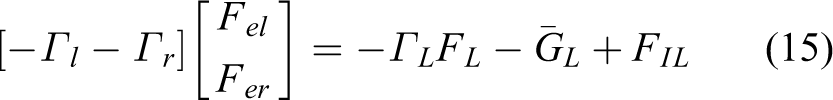
There are various methods for solving the underdetermined equation (15). For example, according to the pseudo-inverse method, we can get generalized forces on the left and right arms

Single-arm impedance control
Through the above analysis, the path and force command of the left and right arms (Xdl , Xdr , Fel , and Fer ) of the robot astronaut during the load handling mission is obtained. To control the position and force of single arm, the position-based impedance control method is used in this article, and its control principal block diagram is shown in Figure 6 (k = l or r, l is for left arm and r is for right arm). 23

Position-based impedance control principle; through the given impedance parameters Md , Bd , and Kd , the F/T deviation ΔFk is converted into the pose deviation ΔXk . F/T: force/torque.
In Figure 6,
End F/T equivalence
Because the six-dimensional F/T sensor in the robotic astronaut is mounted between the elbow roll joint and the two-DOF wrist joint integrated into the dexterous hand. Therefore, the F/T sensor measurements Fsk = [fsk τsk ] need to be converted to the end point of the arm for impedance control. The F/T at the end of the robot astronaut’s arm is shown in Figure 7.
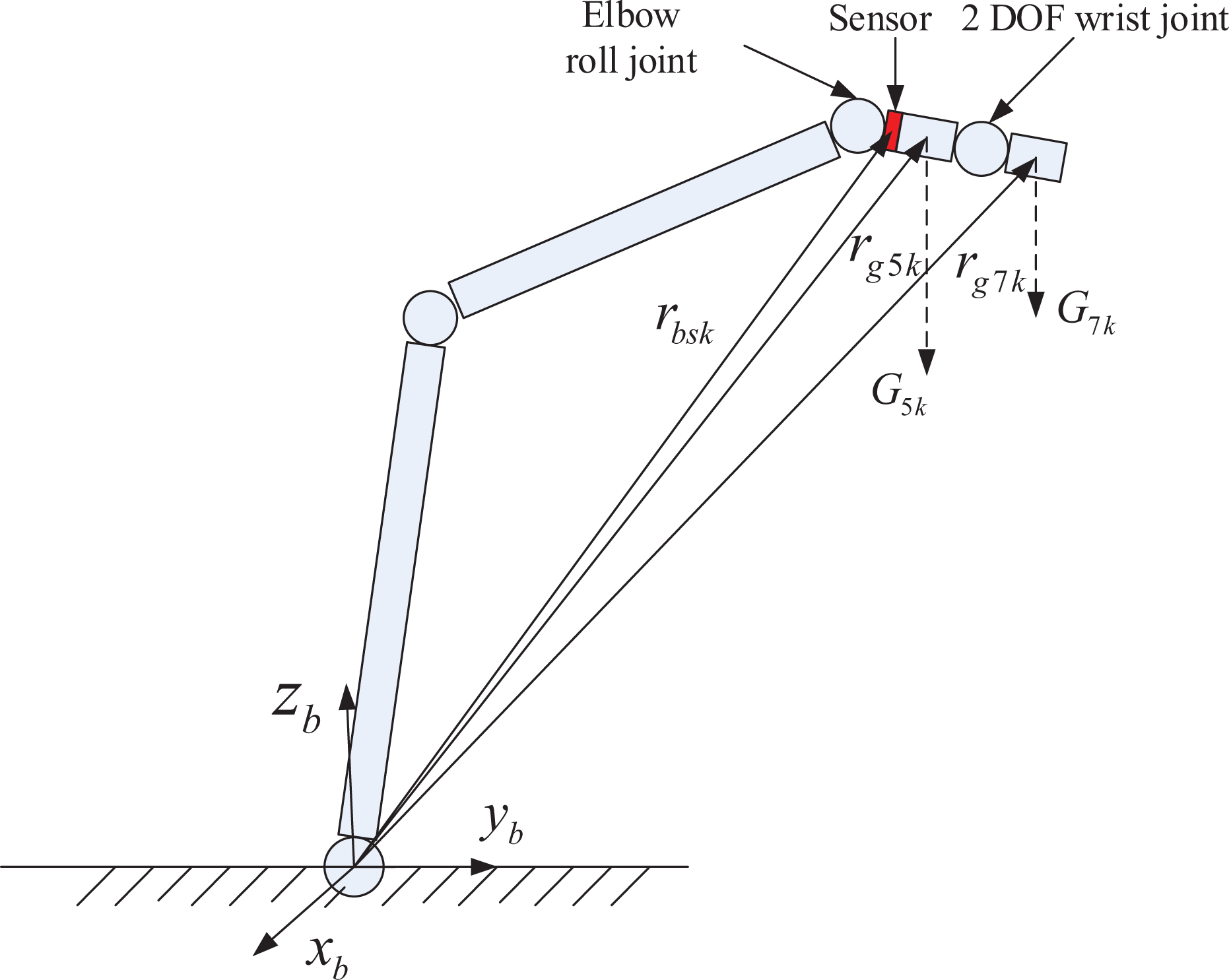
Force analysis at the end of the robot arm, for converting the F/T sensor measurement value to the end point. F/T: force/torque.
Since the robot astronaut’s arm motion speed and acceleration are small, inertia force, centrifugal force, and Coriolis force can be ignored. Therefore, the statics equivalent equation of measuring F/T of sensor to the end of the arm is as follows

where k = l or r, l is for left arm and r is for right arm. fsk is the force vector measured by the F/T sensor, and feka is the calculated equivalent force at the end of the robot arm (the right and left arm’s calculation method is the same)

where
In addition to the equal force, the calculation equation of the equivalent moment τeka at the end of the arm is as follows


In equation (19), τsk is the torque vector measured by the F/T sensor. rbsk is the position vector of the origin of the sensor coordinate system relative to the coordinate system of the base of the robot arm. TGk is the moment of gravity at the end, in which rg5 k and rg7 k are the position vectors of the centroid of the forearm and the five fingers, respectively, in the base coordinate system of the arm, respectively.
Through the above two equations, the measured value of the six-dimensional F/T sensor Fsk can be equivalent to the contact force/moment [feka τeka ] at the end of the left and right arm of the robot astronaut.
Control algorithm simulation
Establishment of the simulation model
To verify the correctness of the coordination force control method, automatic dynamic analysis of mechanical systems (ADAMS) and MATrix LABoratory (MATLAB)/Simulink software are used to establish the dual-arm robot astronaut’s dynamic parametric model and the control algorithm model (Figure 8). The model is composed of load path planner model, inverse kinematics model of the left/right arm, dynamics model of the robot astronaut, impedance control model, and end F/T equivalent model. According to the requirements of the task, the load path planner model decomposes the pose of the load to obtain the desired end pose of the left and right arms. In the inverse kinematics model, the corresponding joint control commands are obtained from the end-pose commands of the robot arm. The dynamics model accepts the joint control command to control the robot astronaut’s motion, and the six-dimensional F/T detected by the sensor is used for subsequent F/T equivalence. The F/T equivalent module receives the six-dimensional F/T measurement value from the dynamics model and calculates the equivalent contact F/T at the end of the robot arm. Based on the error between the expected F/T and the equivalent contact F/T, the impedance control model can obtain the correction quantity of the pose of the end of the robot arm and give it into the inverse kinematics model to obtain the new joint angle command.

Establishment of the co-simulation model using Matlab/Simulink and ADAMS.
The ADAMS dynamic parametric model of the robot astronaut is established by referring to the D-H coordinate system in Figure 9 and the mass inertia parameters of each part of the robot astronaut obtained through the detailed design. As the focus of this article is the control of the coordination force of both arms, the dexterous hand at the end of the arm is simplified to a three-finger clamp and two simplified revolute joints. By driving three wedge blocks to move, the contact between the wedge block and the target cone of the load adapter can be achieved, so as to grasp the target load. The contact between the wedge and the target load adapter cone is measured by the CONTACT function in ADAMS. The force/moment sensor mounted between the fifth joint of the arm and the hand is also simplified in the ADAMS model by adding a fixed pair between the fifth joint and the hand.

Establishment of ADAMS dynamic model of the robot astronaut.
Simulation results
The simulation task flow of dual-arm load handling is as follows: The robot astronaut moves from the initial configuration to the designated pose near the target load (Figure 10(a)), then the end of the arm moves in a straight path, and the end clamping mechanism moves to the clamping point (Figure 10(b)). After that, the three-finger clamping mechanism grasps the target (Figure 10(c)). According to the force control method in the fifth section, the left and right arm coordinate to transport the load along the z-direction (Figure 10(d)). The weight of the load to be transported is 3 kg, and it is a 400 × 400 × 400 mm cube. In Figure 10(c), the joint angles of the left arm joints are 76.33°, 59.29°, 89.06°, 124.63°, 138.13°, 131.49°, and 51.24°, and the joint angles of the right arm joints are 96.21°, −57.39°, 102.42°, −125.34°, −138.00°, −131.64°, and −62.32°). The initial position and attitude of the load centroid coordinate system oL_xL_yL_zL relative to the robot’s own system ob_xb_yb_zb are 600 mm, 0 mm, 272 mm; 0,0,0. The end position and attitude of the load movement are 600 mm, 0 mm, 222 mm; 0,0,0.

Load transporting simulation process: (a) moves from the initial configuration to the designated pose near the target load, (b) the end clamping mechanism moves to the clamping point, (c) the end clamping mechanism grasps the target, and (d) transport the load along the z-direction.
In master–slave force control mode, it is assumed that the left arm is the master arm and the right arm is the slave arm. According to the above master/slave control strategy, the end contact force vector Fel of the left arm is given in advance and it is [5 N, 20 N, 4 N, 0 Nm, 0 Nm, 0 Nm]. The simulation is conducted in a gravity environment. The direction of gravity is along the −y-axis (as shown in Figure 10(a)), and the weight of the load is 3 kg. According to equation (14), the force command of the right arm can be calculated as [−5 N, 9.4 N, −4 N, 0 Nm, 0 Nm, 0 Nm]. The impedance control parameters of the slave arm are Md = diag([5 40 5 1 1 1]) (kg, kgm2), Bd = diag([200 1200 200 30 30 30])(Ns/m, Nms/rad), and Kd = diag([5000 9000 5000 150 150 150])(N/m, Nm/rad).
Figure 11 shows the force response of the left and right arms when the master–slave force control mode is adopted. The arms are in the state of Figure 10(c) at 0 s and the state of Figure 10(d) at 5 s. For the left arm, the force of the left arm along the x-axis and z-axis are 0 at the initial state and then rose to 5 and 4 N within 0.5 s according to the force control commands (Figure 11 (a) and (e)). Since the simulation is carried out in a gravity environment with a load weight of 3 kg and the left arm is the active arm, the force received by the left arm along the y-axis is the load gravity of 29.4 N at the beginning of the simulation. When the two arms start working together, the force of the left arm gradually decreases to 20 N, which is the given force command of the left arm along the y-axis (Figure 11(b)). For the right arm, since the total net force of the load along the x-axis is 0, the end force of the right arm in x-direction rises to −5 N, which is opposite to the end force of the left arm (Figure 11(b)). Since the simulation is carried out in a gravity environment with a load weight of 3 kg, the force of the right arm in y-direction is gradually increased to 9.4 N to overcome the load gravity in coordination with the left arm (Figure 11(d)). As shown in Figure 11(f), in z-direction, the force is bigger than −4 N because of the acceleration of the load along the positive z-axis at the first second. From 1 s to 4 s, the load moves uniformly along the z-axis, so the force on the right arm along the z-axis is −4 N, just in balance with the force on the left arm along the z-axis. From 4 s to 5 s, the load needs to slow down until it stops, so the force on the load from the right arm is less than −4 N to get the acceleration along the −z-axis.

The force curve at the ends of the arms in master–slave force control: (a) force in x-direction of the left arm, (b) force in x-direction of the right arm, (c) force in y-direction of the left arm, (d) force in y-direction of the right arm, (e) force in z-direction of the left arm, and (f) force in z-direction of the right arm.
As can be seen from the Figure 11, the desired force in all directions is well controlled and meets the control requirements. Figure 12 is the end position deviation of the slave arm in the process of master–slave force control process. As can be seen from the figure, the position deviation curve tends to be stable with the passage of time, and the position stability error along the x, y, and z axes is less than 1 mm.

The position deviation of the slave arm in master–slave control mode: (a) x-direction, (b) y-direction, and (c) z-direction.
Figures 13 and 14 are simulation results using shared force control. A sinusoidal external force is applied to the load in the x-direction, and the load whose weight is 3 kg is grasped by both arms under gravity environment. The impedance control parameters of both arms are Md = diag([5 40 5 1 1 1]) (kg, kgm2), Bd = diag([200 1200 200 30 30 30])(Ns/m, Nms/rad), and Kd = diag([5000 9000 5000 150 150 150])(N/m, Nm/rad). According to the principle of shared force control mode, the force commands at the end of the left and right arms are obtained according to equation (15). Then, impedance control is carried out on the left and right arms, respectively. Figure 13 is the force response curve of both arms end. As can be seen from the figure, the left and right arms track the force commands very well along the x, y, and z directions. Figure 14 is the end position deviation of the right arm in the process of share force control process. As can be seen from the figure, as the contact force changes, the error compensation value also changes, ensuring that the contact force has a good following effect on the expected contact force. Comparing Figures 12 and 14, it can be found that the master–slave force control mode has better position control accuracy than the shared force control mode.

The force curve at the ends of the arms in shared force control mode: (a) force in x-direction of the left arm, (b) force in x-direction of the right arm, (c) force in y-direction of the left arm, (d) force in y-direction of the right arm, (e) force in z-direction of the left arm, and (f) force in z-direction of the right arm.
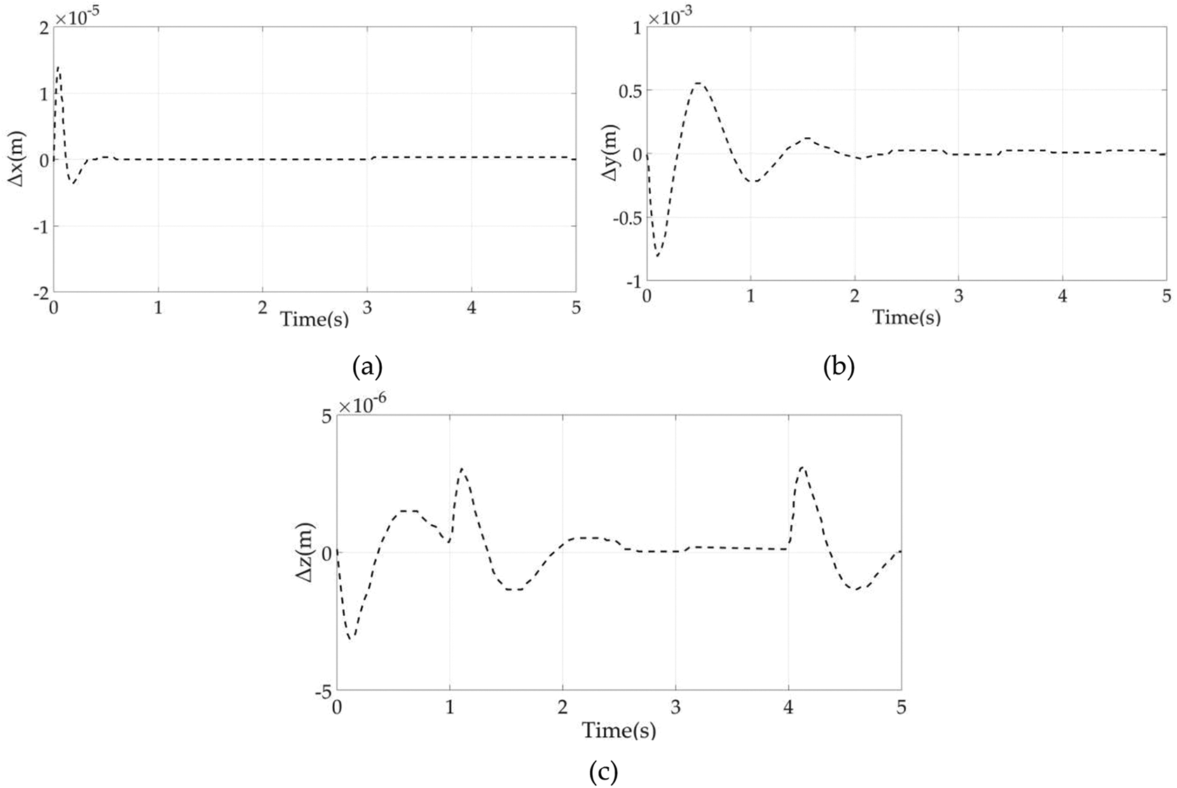
The position deviation of the right arm in shared force control mode: (a) x-direction, (b) y-direction, and (c) z-direction.
To analyze whether there is a significant difference between the two control methods, the force control data in Figures 11 and 13 were analyzed by one-way analysis of variance (ANOVA). The ANOVA results of the left and right arm force control are presented in Tables 2 and 3. Assuming that there is no significant difference in the force response errors of the two control methods, when the progressive significance is less than the significance level of 0.05, the null hypothesis is rejected; otherwise, the null hypothesis is accepted. It can be seen from Tables 2 and 3 that the progressive significance of the force deviation in the x, y, and z directions of the left and right arms is greater than the significance level of 0.05, so it is believed that there is no significant difference in the force errors of the two control strategies in each direction of the left and right arms.
Left arm force ANOVA.
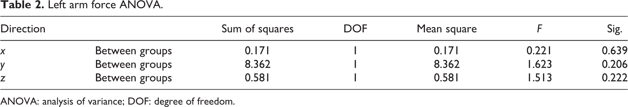
ANOVA: analysis of variance; DOF: degree of freedom.
Right arm force ANOVA.

ANOVA: analysis of variance; DOF: degree of freedom.
In the same way, the position control response data in Figures 12 and 14 are subjected to a one-way ANOVA, and the results are presented in Table 4. The progressive significance of the position deviation of the two control methods is far less than 0.05, that is, the two control methods have obvious differences in the accuracy of the position control. The shared force control method has a higher position control accuracy.
Position ANOVA.

ANOVA: analysis of variance; DOF: degree of freedom.
Comparing the two kinds of control mode, the distribution of generalized force at the end of the arm in master–slave mode has a clear task directivity, which can determine the operating force of left and right arm in advance according to the task requirements, which can make the completion of some work tasks with special force requirements more perfect. In the shared control mode, the distribution of generalized force has no task directivity, and it is impossible to assign the end force of a certain arm explicitly according to the specific requirements of the task. So, it is better to choose master–slave mode for tasks with explicit force distribution requirements. The shared force control strategy of dual-arm coordinated operation decomposes the load force balance equation directly. The load internal force in closed-chain state is controlled at the desired range in real time by considering the end-effector operational forces of dual arms simultaneously. Dual arms satisfied closed-chain constraint equations are controlled cooperatively. The highest priority of this mode is achieving the desired motion of load, so shared force control is especially suitable for high-precision requirement of load path.
Discussions and conclusions
Most studies about dual-arm coordinated operation focus on load distribution and internal force analysis. However, it is complicated to solve these dynamic equations. In this article, to reduce the complexity and the difficulty of solving dual-arm’s end pose and force commands, the closed-chain kinematics and dynamics theoretical model of the dual-arm robot astronaut is established firstly, and some constraint conditions are introduced according to the task characteristics of space payload operation. Two different control strategies, master–slave force control, and shared force control are adopted, respectively, according to the different constraints introduced. A fully parametric dual-arm coordinated force control simulation framework based on MATLAB/Simulink and ADAMS software is also proposed in this article. The model takes into account the inverse kinematics solution of the seven-DOF redundant manipulator and the end F/T equivalent problem, which is caused by the six-dimensional force sensor not being installed at the manipulator’s end. Simulation results show that the step response of the end force can be stabilized within 1–2 s, and the accuracy of position control can reach the millimeter level. ANOVA shows that the two control methods have no obvious difference in the accuracy of force control but the shared force control method has a higher position control accuracy, and this proves that the master–slave mode is better for tasks with explicit force distribution requirements and the shared force control is especially suitable for a high-precision requirement.
Footnotes
Acknowledgement
The authors gratefully acknowledge the financial supports by the National Key R&D Program of China.
Declaration of conflicting interests
The author(s) declared no potential conflicts of interest with respect to the research, authorship, and/or publication of this article.
Funding
The author(s) disclosed receipt of the following financial support for the research, authorship, and/or publication of this article: This work was supported by the National Key R&D Program of China (2020YFC2005800 and 2020YFC2005804).