
Abstract
This article presents a methodology for the design of a pair of wearable robotic appendages, known as Supernumerary Robotic Limbs, or SuperLimbs for short. Specifically, we aim to design SuperLimbs for assisting astronauts while they perform partial-gravity Extra-Vehicular Activities (EVAs) on the Moon. NASA has identified recovering from a fall as a high-risk process needing an effective countermeasure. Preliminary human study data discovered uniform behavior in astronaut’s poses as they performed a post-fall recovery wearing a space suit assembly. Based on this observation, this paper presents a complementary biomechanical model which estimates the torques required by an astronaut to navigate their body through a post-fall recovery. By comparing maximum allowable joint torques of the astronaut with the required joint torques, we identify the gap that SuperLimbs must fill by exerting necessary forces along a desired trajectory. A parametric optimization problem is formulated for designing SuperLimbs that meet these requirements with least energy consumption. A two-phase design optimization method is developed. Phase 1 consists of utilizing a coarse-grid AI searcher that rules out invalid designs that do not meet basic functional requirements. Phase 2 uses the optimal permutation from Phase 1 as an initial estimate for a fine-grid parameter-sweep optimization where energy dissipation across the actuators and task-space tracking accuracy are used as performance metrics. Based on the optimal design, an Earth-based prototype is built in-house at the NASA Jet Propulsion Laboratory, and its feasibility for astronaut’s fall recovery assistance is evaluated.
Keywords
Introduction
In recent years, there has been a resurgence in humanity’s interest toward human spaceflight. Commercial companies, like that of SpaceX, Blue Origin, and Intuitive Machines, have been tasked with aiding NASA in putting “boots on the moon” by the early 2030s by means of the Artemis Program (Bridenstine, 2020), which takes on an ambitious plan to establish and retain a permanent human presence on the moon.
Astronauts are the most important and critical assets to carry out successful human spaceflight missions. Missions can contain tasks from managing various spacecraft subsystems all the way to performing scientific experiments. However, among all of the tasks an astronaut can perform, Extra-Vehicular Activities (EVAs) are considered the most complex and dangerous (Dunn et al., 2022). Many attributes contribute to the intercomplexities and challenges associated with an EVA, but one unavoidable component of EVAs is the use of a pressurized space suit, which must maintain a pressure of 29.7 kPa (4.3 psi) with the vacuum environment (Ross et al., 2019).
A space suit acts as a human-shaped spacecraft, allowing astronauts to traverse the harsh environments in space and extraterrestrial bodies. However, the space suit’s inherent design by necessity subjects the astronaut wearers to: Bearing additional mass of the Space Suit Assembly (SSA) and Portable Life Support System (PLSS), often equivalent to the mass of the astronaut wearer (Norcross et al., 2010). Limiting movement and restricted range-of-motion due to the pressurized SSA, which contributes to increased joint stiffness (Holschuh et al., 2009).
The space suit’s limitations on an astronaut reduce their overall working efficiency and increase the grid of unsafe conditions that can befall them while they carry out an EVA (Anderson et al., 2012; Belobrajdic et al., 2021; Carr and Newman, 2007). For example, the additional mass introduced by the PLSS shifts the astronaut’s Center of Mass (CoM) rearward, forcing astronauts to lean forward to maintain an upright posture (Sridhar et al., 2017). Furthermore, astronauts must overcome the stiffness of the pressurized space suit to perform any physical task, from moving their arms and legs to flexing each individual finger, causing significant muscle strain (Gernhardt et al., 2009).
Space suit designers and missions planners have tried since the Apollo era to find effective solutions to improve the overall safety and ergonomics of suited EVAs, such as lowering the space suit’s operating pressure below 29.7 kPa to improve mobility (Abramov et al., 1994), use of rigid bearing assemblies (rather than pressurized garments) around joints to promote flexibility (Abramov et al., 2001), and use of a mechanical counter-pressure suit to earn astronauts full mobility and flexibility like on Earth without a space suit (Bethke et al., 2004). Despite the plethora of design options for future planetary space suits, massive tradeoffs are prevalent, where productivity and viability are sacrificed.
Recently, the authors group has proposed to apply Supernumerary Robotic Limbs to supplement astronaut capabilities (Ballesteros et al., 2023; Ballesteros et al., 2024) through the use of wearable robotics technology. Astronaut capabilities can be augmented, and an effective means to offset loss of utility and mitigate safety risks in suited EVA operations can be gained. Supernumerary Robotic Limbs, or SuperLimbs for short, are a type of wearable robot that, unlike an exoskeleton, can assume a kinematic structure independent of the wearer’s posture, effectively giving the user an additional set of appendages (Eden et al., 2022; Guggenheim et al., 2020; Parietti and Asada 2016; Parietti et al., 2014). The SuperLimbs’ unique feature opens new possibilities to augment the user in numerous ways. Figure 1 is a Concept of Operations (Con Ops) diagram depicting some of the high-level use cases of SuperLimbs augmenting a suited astronaut wearer. Concept of Operations (Con Ops) of astronaut/SuperLimbs synergy during lunar Extra-Vehicular Activity (EVA).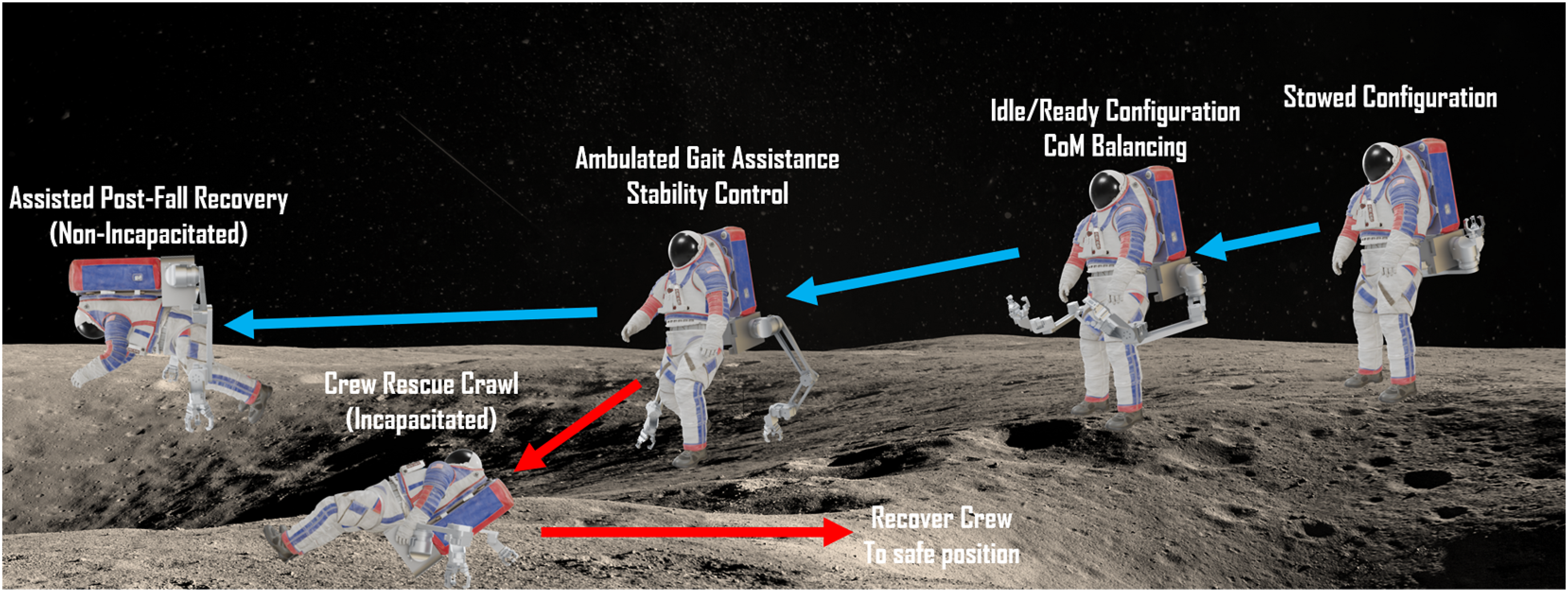
Despite the promising features and potentials of SuperLimbs, it is a challenge to design a SuperLimbs system that can effectively augment an astronaut’s physical capabilities and that meets stringent requirements for space applications. First, the extra load and restrictions applied to the astronaut must be characterized, and the reduced physical capabilities in suited EVAs must be modeled to determine functional requirements of SuperLimbs. It would be desirable to have knowledge on how SuperLimbs can best assist an astronaut for a particular high-priority application. If the SuperLimbs can be demonstrated to provide for a high-loading/high-priority application, then the design can effectively deliver on other lower-loading/lower-priority applications. We will present a methodology for designing a pair of SuperLimbs based on a biomechanic model competent to characterize an astronaut’s physical capabilities when wearing a space suit.
For our study, we chose for our high-load/high-priority application of SuperLimbs to be focused on a specific area of technological gap that must be filled for successful EVAs on the Moon and beyond. NASA has identified recovering from a fall as a high-risk process that requires an effective countermeasure (Dunn et al., 2022; Gernhardt et al., 2009; Lowry and Charania, 2024). Since the Apollo era, it has been known that walking on the Lunar surface is challenging for suited astronauts. Many falls have been reported and, more importantly, recovery from a fall requires a significant amount of time and effort, impacting EVA missions (Thuro and Stirling, 2021).
This article aims to establish a SuperLimbs design methodology that physically assists astronauts, but can be extended to use on applications beyond just astronauts (such as assistive eldercare, construction workers, etc.). Taking post-fall recovery assistance as an exemplary case study, we make the following contributions: (1) Perform an extensive retrospective on experimental data performed in prior works to investigate the challenges associated with post-fall recoveries wearing a space suit. From that study, obtain a biomechanical model that can inform us about the ergonomics of astronauts. (2) Using the model, extract critical performance requirements that will govern the kinematic design of the SuperLimbs. (3) Rigorously down-select from the space of all possible design combinations for SuperLimbs to a kinematic design of SuperLimbs that is compliant to the aforementioned performance requirements. (4) Develop a physical prototype of SuperLimbs to be used as a demonstration and implementation testbed and demonstrate it satisfying the aforementioned performance requirements.
Suited post-fall recoveries
Preliminary human studies and key takeaways/observations
To better understand the challenges associated with recovery after the fall of astronauts, pilot human studies were conducted (Ballesteros et al., 2024). An in-house analog space suit was developed that mimics the mass/inertia, size, and mobility of NASA’s Exploration Extravehicular Mobility Unit (xEMU) (Ross et al., 2018; Yarlagadda, 2023). Test participants were asked to stand up wearing the analog space suit with a heavy backpack from various initial postures.
Two observations were initially made for the pilot human studies concerning astronaut recovery following a fall. First, post-fall recovery trajectories were characterized as a sequence of statically stable poses, called “waypoints.” From Figure 2, waypoints are labeled as S1, S2, S3 for Supine waypoints, P1, P2, P3 for Prone waypoints, C for Crouch, and U for Upright. Adjacent waypoints can be interpolated with a simple geometric path about specific joints on the body. Simple model representation of astronaut post-fall recovery (Left) and representation of the sequence of waypoints (bolded) taken by humans to perform post-fall recoveries. Solid black paths are to represent the most straightforward/common paths taken (suited), while dashed paths represent alternative/less common paths taken (unsuited) (Right) (Ballesteros et al., 2024).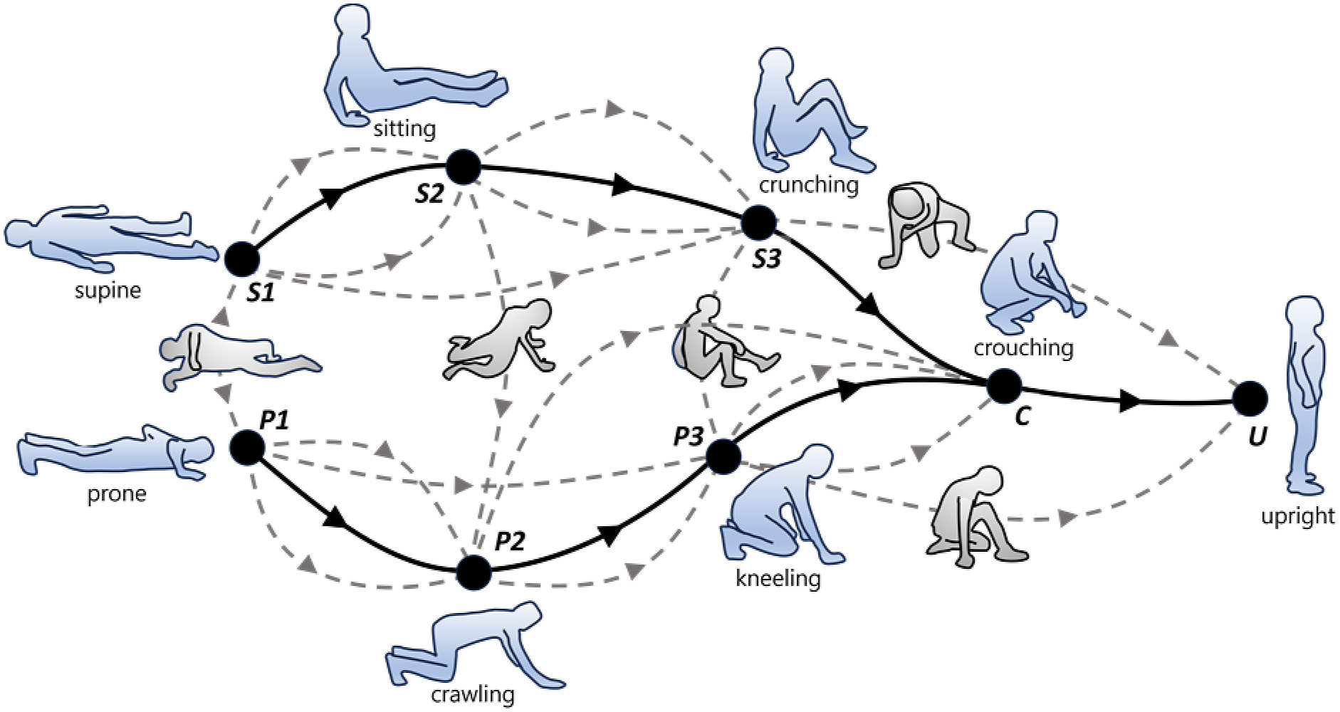
Second, humans, when unconstrained, can stand up from various initial postures through a plethora of varying paths. Normally, the path selected by an individual human subject differs significantly depending on the individual subjects. Figure 2 represents the variability of the paths a human can take to perform post-fall recovery. However, when a human is constrained, particularly by that of a space suit (high joint stiffness, joint bearings, and mass/inertial load (including the heavy backpack)), the path selected became more deterministic and unified; the sample population of test subjects took the paths indicated by solid lines in the figure. All the successful recovery cases are along the same prone route:
In further examination of the data, we have made the following observations: The majority of human subject movements are symmetric with respect to the sagittal plane. When the initial posture is neither supine nor prone, the human subject first rolls into S1 or P1. This makes sense because the backpack is heavy and significantly shifts the center of mass backwards. If they attempt to raise the upper body without rolling into the symmetric posture, they must cope with a large rolling moment while lifting the upper body. Therefore, all human subjects first rolled to take a symmetric posture and remained within the sagittal plane. Both legs and arms are used in the early stage of recovery effort, P1 to P2 and S1 to S2. However, the later stage, arms cannot reach the ground. The transitions from S3 and P3 to C and then U are solely by the legs. The challenges are those transitions with legs alone, and the hardest is the transition from S3 to C. As such, all successful recovery cases are along the prone route: Initial rolling
Model development to complement the human studies
Simplified suited astronaut model
Based on the preliminary experiments, we construct a simple model that is competent to capture key features of the post-fall recovery process of astronauts. Anthropometry of a typical male astronaut was utilized for the development of this model, as defined in Kim et al. (2019). We make the following assumptions as we developed the model: The astronaut’s movements are constrained within the sagittal plane. As observed in the preliminary experiments, all the successful fall recovery movements are within the sagittal plane. We assume that the body movements are symmetric with respect to the sagittal plane. As addressed later, a pair of SuperLimbs to be designed can assist the astronaut in maintaining the body position within the sagittal plane. The body posture of the suited astronaut can be approximated to a 7-link kinematic chain, as shown in Figure 3. Following Newman et al. (2000), the upper body, including the torso, chest, and head, is treated as a single rigid body, called the Hard Upper Torso (HUT). The mass of the HUT, including the PLSS and the upper body of the SSA, dominates the entire mass. Therefore, the location of CoM relative to HUT does not shift although the arms and legs of the astronaut take different postures. The human body motion is quasi-static, which would be desirable for an astronaut’s suited post-fall recovery (Walton et al., 2024). Inertial forces and moments are negligibly small.
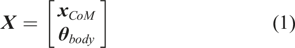
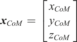
Under these assumptions, the complete set of generalized coordinates to locate the 7-link system is given by Astronaut Body Model depicting the state of the astronaut body CoM as well as the pose of the astronaut’s appendages projected along the sagittal plane, taken at the Prone 1 (P1) waypoint to the Prone 2 (P2) waypoint. The model is assumed to be symmetrical with respect to the sagittal plane. The CoM is tied rigidly to the Hard Upper Torso (HUT) linkage (depicted in red) with an offset to account for the shift in the astronaut body/SSA/PLSS CoM rearward.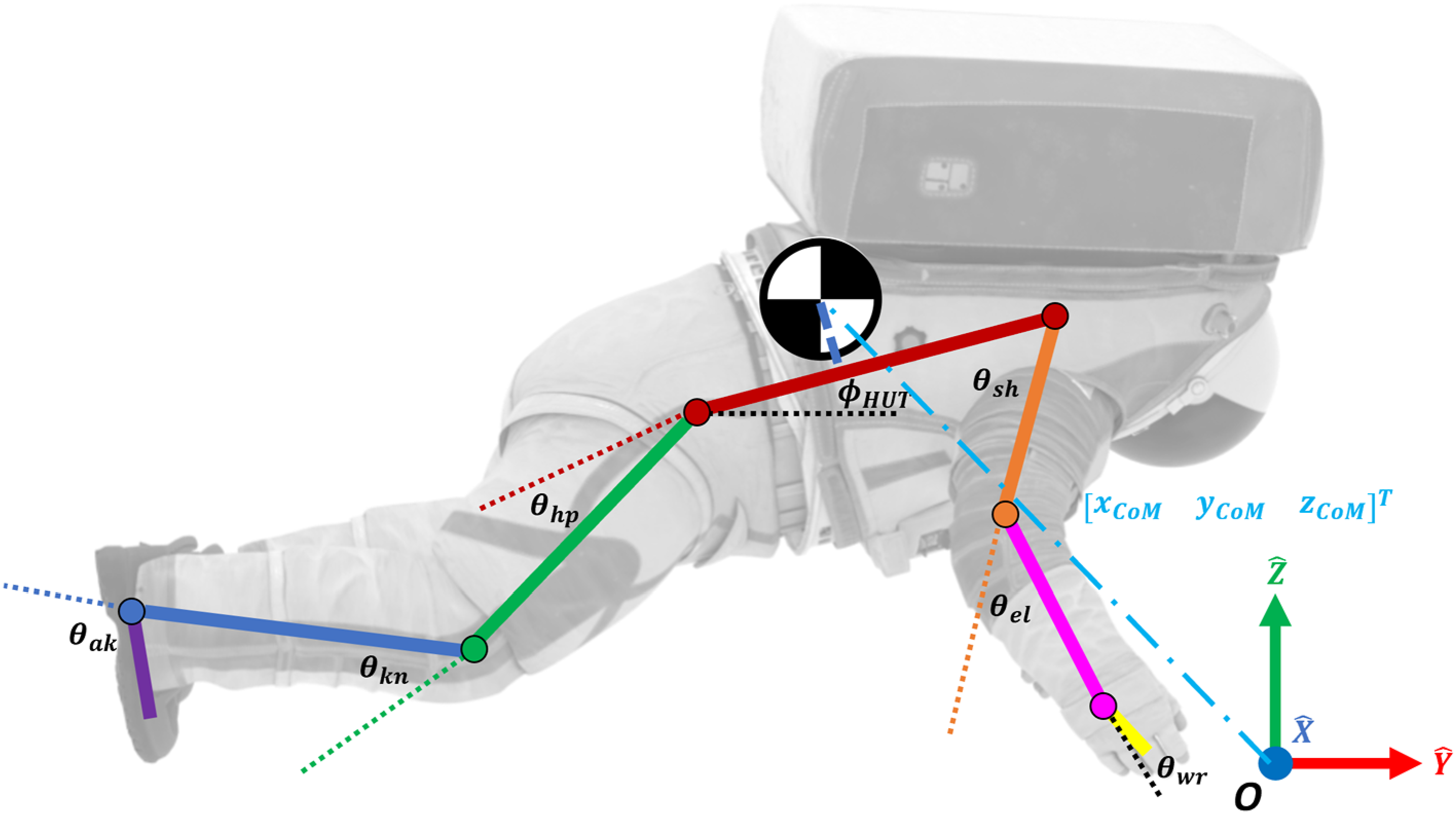

Astronaut/joint exertion—task-space forces model
A second biomechanical model is developed to compare the maximum voluntary joint torques of the astronaut with the joint torques required during post-fall recovery.
For each phase of post-fall recovery (paths between each waypoint), a static bracing analysis is conducted to determine the activated joint torques in the astronaut’s body necessary to brace the mass of their body and the space suit.


The Jacobian takes a different form depending on the posture of the astronaut during the post-fall recovery. When the astronaut’s arms contact the ground, the gravity load is born by both legs and arms. As a closed-loop kinematic chain is formed in such a case, the joint torques are not uniquely determined. However, it is known in biomechanics literature that the human takes a particular solution among many that minimizes the total effort required for bearing a load (Crowninshield and Brand, 1981; Daniel et al., 2022; MacConaill, 1966). Based on this principle, we can uniquely determine the joint torques although both legs and arms share the gravity load.
Let

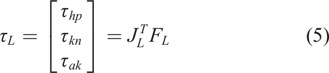
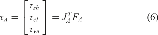


Note that during the transition C to U, the arms do not touch the ground and no closed-loop kinematic chain is formed. Depending on the transition stage, the relevant joints are different. In general, the legs bear more load than the arms. Figure 4 shows the estimated torques at the relevant joints during the quasi-static transitions from P1 to P2, P2 to P3, P3 to C, and C to U. The solid blue lines indicate joint torques required for bearing the gravity load. Profiles of torques across joints in the astronaut’s legs throughout all phases of post-fall recovery. Required torques to be exerted by the astronaut is depicted by the sum (solid black line) of the static bracing torque (solid blue line) and torque necessary to overcome the stiffness of the pressurized Space Suit Assembly (SSA) (dashed orange line). The maximum allowable voluntary joint torque that an astronaut can exert (dotted green line) is overlapped. The region in red represents the torque gap required to be filled by an external force. Regions where the maximum voluntary torque are greater than the required torque indicates where an astronaut can apply load without assistance (cyan shaded region), while regions where the required torque exceeds that of the maximum voluntary torque indicates a need for external force/assistance (red shaded region).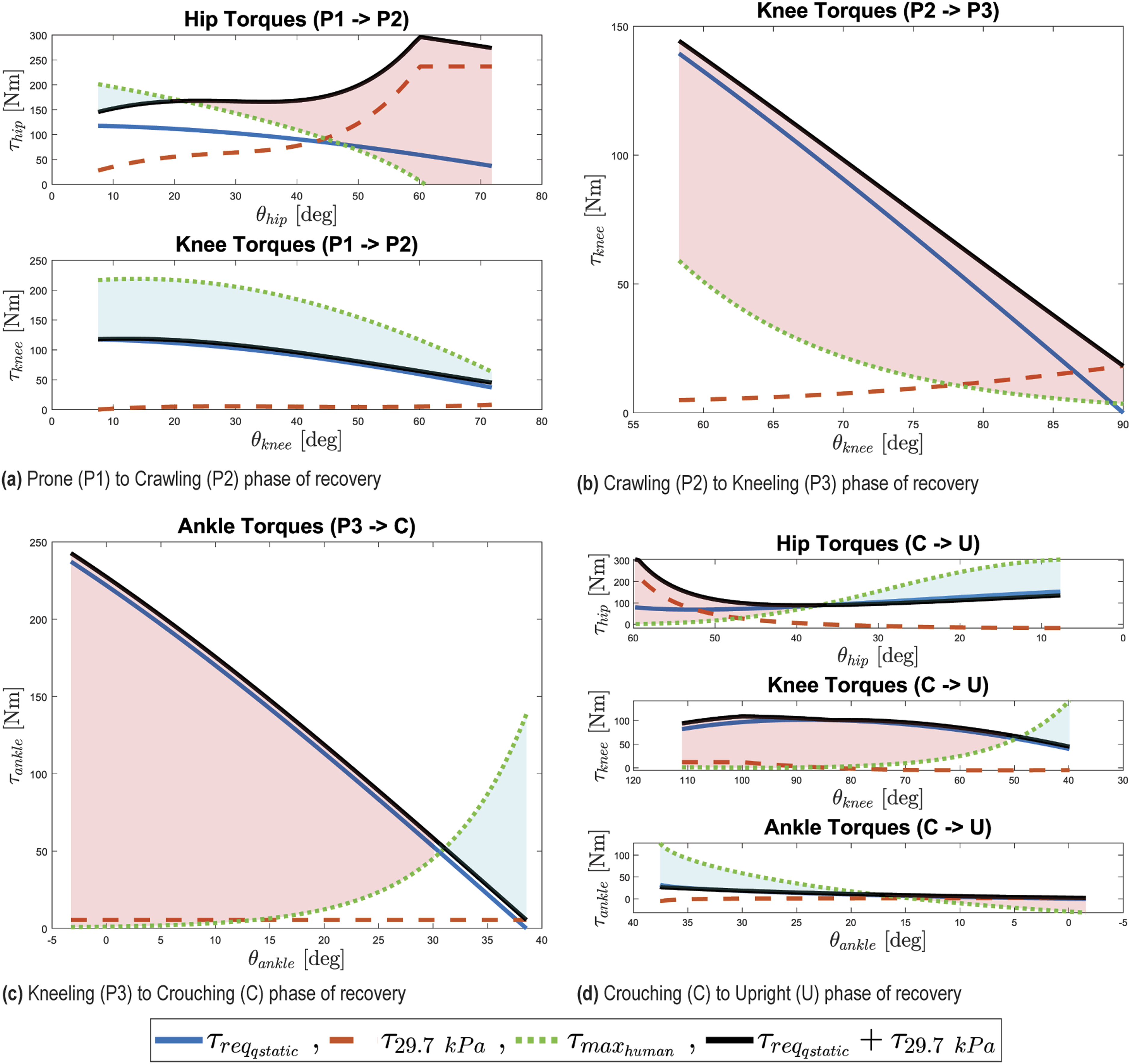
See Figure 3.
In addition to the static bracing torque required by the astronaut, they must also overcome the stiffness of the pressurized SSA. Diaz and Newman (2014) characterized and cataloged the joint torques necessary to overcome the SSA stiffness for the entire operational range of the NASA Z-2 EVA suit.
The required joint torques can be found by taking the sum of the static bracing torque in the astronaut joints necessary to support their own mass and the space suits (assuming quasi-static motion) and the joint torque required to overcome the stiffness of the space suits’ joints.

The maximum voluntary joint torque of astronauts can be estimated based on the human model of Anderson’s maximum voluntary joint torque (Anderson et al., 2007). The regions along the trajectory where the required joint torques exceed the astronaut’s maximum voluntary joint torques indicate a gap where SuperLimbs assistance is required. The practice of assessing regions where the astronaut lacks the capability to exert enough joint torque was exercised across each phase of post-fall recovery for every substantially contributing joint and cataloged in Figure 4. The solid black line indicates the total required joint torque including the one for bracing the body and the one for overcoming the space suit stiffness. The green dashed line indicates the maximum joint torque that astronauts can exert. The difference shown by the red area represents the gap, the torque that SuperLimbs must supply.
To determine the assistive forces required by SuperLimbs, the difference between the required joint torques and the maximum voluntary joint torques must be computed.

For computing the forces to be generated by SuperLimbs, the torque gap
For transition phases where only legs support the load,


For phases of post-fall recovery where motion can be approximated to a rotation about a single joint (P2 Astronaut Applied Torque model, taken at the Prone 3 (P3) waypoint to the Crouching (C) waypoint, where the entire torque applied by the astronaut body can be approximated as applying a torque about the ankle joint to move the astronaut body/SSA/PLSS CoM in a circular path. The grid of external augmentation is determined by first taking the difference between the required torque to move the astronaut through the path (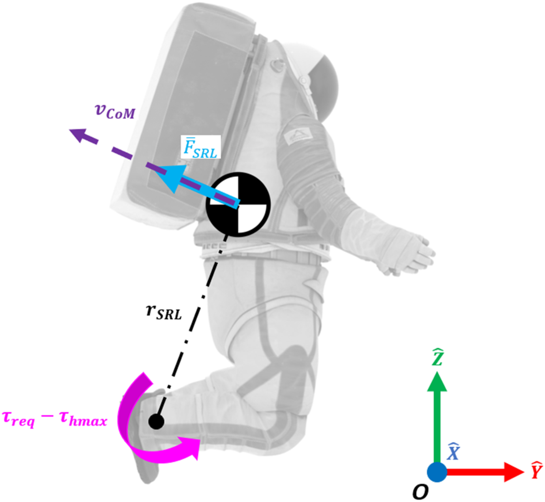
Applying equations (10)–(13) across the entire post-fall recovery trajectory provides the forces necessary for a set of SuperLimbs to effectively assist an astronaut. Provided the necessary task-space trajectory, shown in Figure 6(a), and task-space forces, shown in Figure 6(b), required from a set of SuperLimbs to effectively augment the safety of an astronaut and reliably perform a post-fall recovery, we can now devise a process to determine an effective design of the SuperLimbs. Task-Space astronaut CoM trajectory and required SuperLimbs reaction forces for post-fall recovery. Note: SuperLimbs required force acts along the direction of motion of the astronaut’s CoM.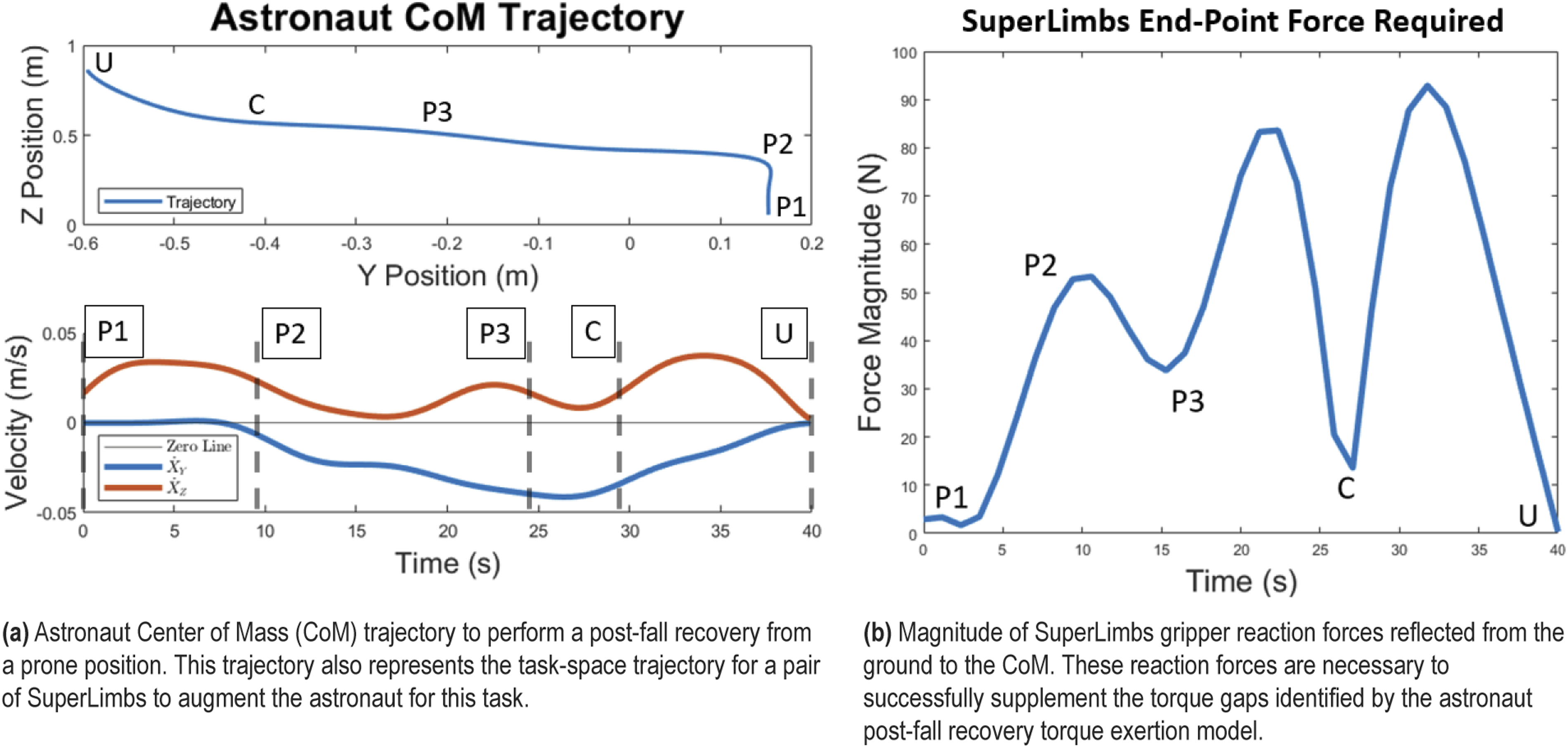
Design methodology
Parametric model for design
We aim to find an optimal SuperLimbs design for the post-fall recovery task. We first parameterize the structure of SuperLimbs and introduce additional parameters associated with the task. The former is called intrinsic parameters, while the latter are extrinsic parameters.
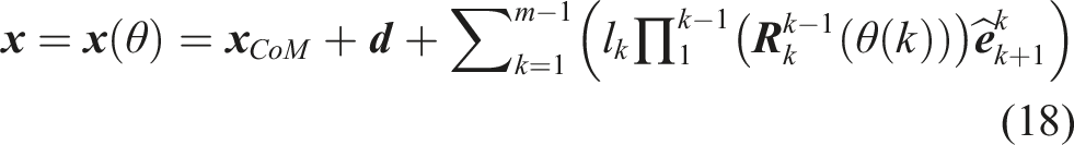
Considering a class of SuperLimbs design with
Each SuperLimbs design will be evaluated with respect to task performance. Two sets of extrinsic parameters are required; one is to represent where on the ground the SuperLimbs are to be placed, and the other is where on the astronaut’s body the SuperLimbs are attached. Representation of extrinsic properties of SuperLimbs design.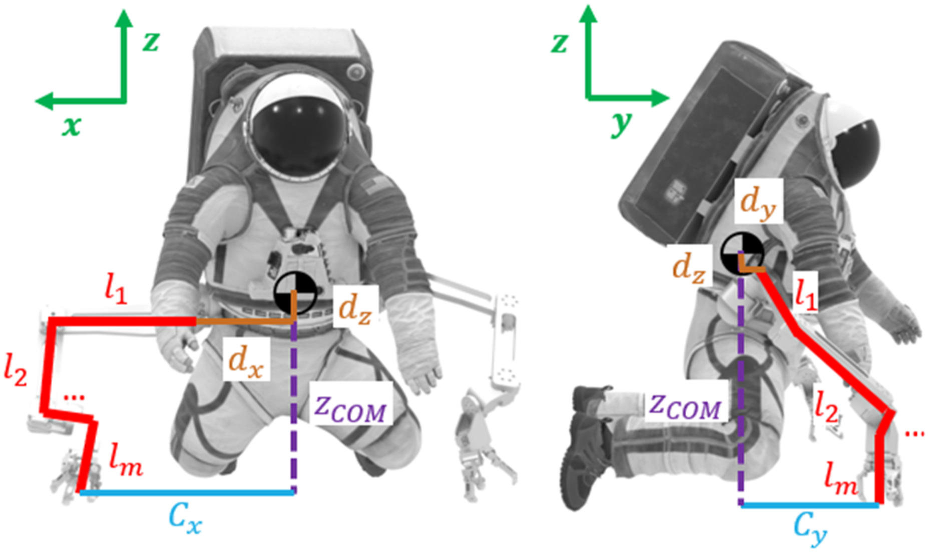


Functional Requirements
Desirable SuperLimbs designs must satisfy basic functional requirements and conditions (FRs). We consider the following requirements:
Down-selection of SuperLimbs designs via coarse-grid AI search
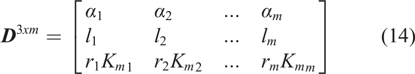
Provided that a SuperLimbs design can be expressed as a set of design parameters given by equations (14)–(16), we can observe that the entire design space is of
To begin determining the design of a set of SuperLimbs optimal for augmenting an astronaut performing a post-fall recovery, we can define a feature tree that expresses all possible combinations of SuperLimbs designs. By segmenting each design parameter by discrete grid points (10 equally spaced parameter values per parameter within a specified range for each parameter), we can express the feature tree with a total of 5.4 million permutations (possible combinations of SuperLimbs designs). Permutations within this defined feature tree were evaluated and filtered by the basic functional requirements and specifications defined previously. Using a backtracking algorithm (Bordeaux et al., 2006; Esposito et al., 1997) to prune the branch of the design tree, we can perform an effective evaluation of the entire discrete design space. Figure 8 illustrates the coarse-grid AI Search down-selection process. Representative flow diagram of the coarse-grid AI search algorithm. 5.4 million design permutations are filtered by engineering constraints defined as functional requirements. Branches of the SuperLimbs design feature tree are pruned via the backtracking algorithm (Bordeaux et al., 2006; Esposito et al., 1997). Valid designs are then ranked by performance metrics of the kinematic structure.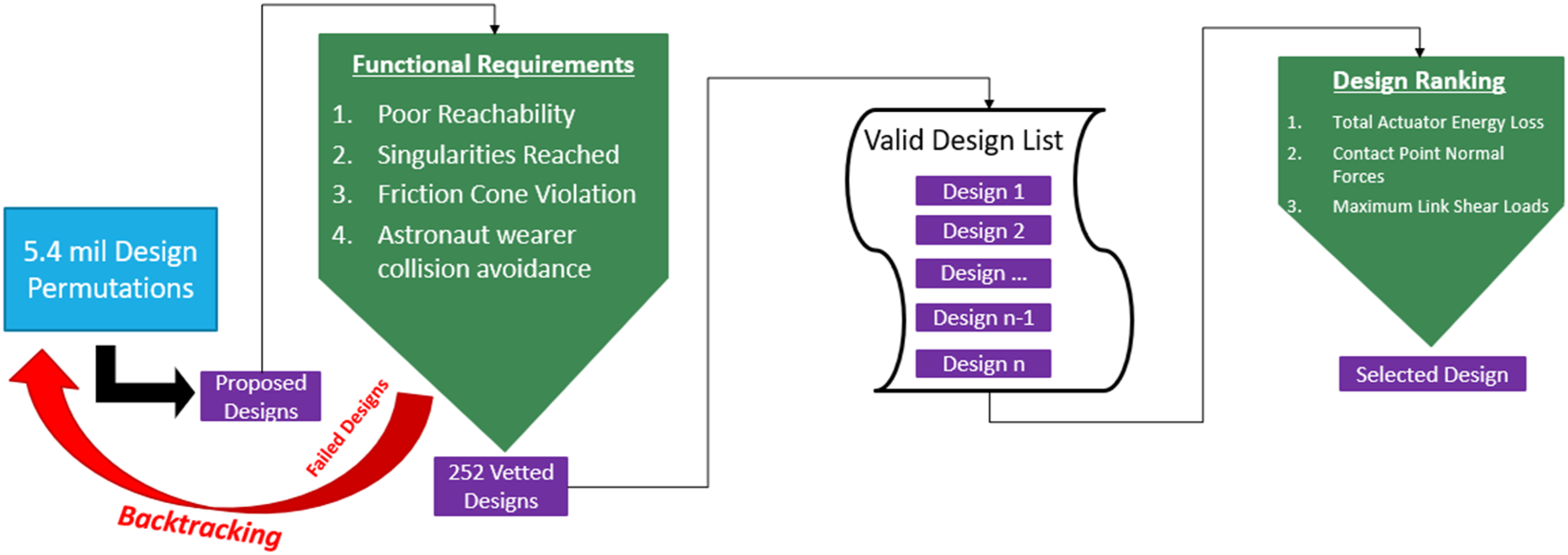
Fine-grid localized optimization
Once SuperLimbs designs that meet all basic functional requirements and specifications have been obtained through the coarse-grid AI search, we can find the final optimal design through a fine-grid optimization using a quantitative performance index. We can treat parameter values of each grid point selected via the AI search as an initial estimate, and conduct a fine-grid optimization locally.
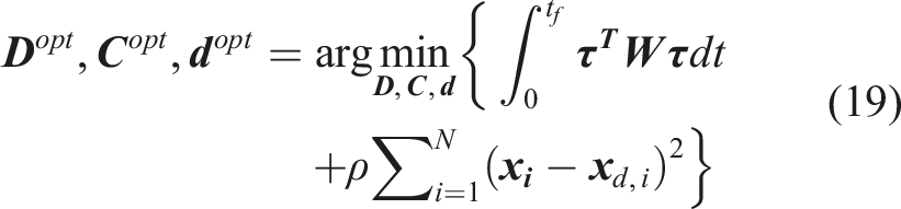
Subject to

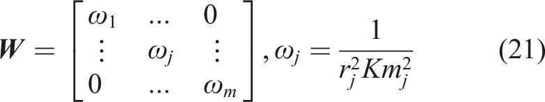
The actuator-generated torque
Note that the SuperLimbs may undergo dynamic movements during post-fall recovery. Despite the fact that we assume quasi-static motion for the astronaut CoM in the task space, the same assumption cannot hold for the SuperLimbs behavior in the joint space. For example, as the SuperLimbs approaches a singular point, the SuperLimbs’ joint angular accelerations may be significantly large, despite the fact that the end-effector velocities in the task space (the astronaut CoM in this case) is small.
The penalty function rules out combinations of intrinsic and extrinsic parameters that do not allow the SuperLimbs to reach the required endpoint position or, due to singularity, the Inverse Kinematic (IK) solutions are erratic. The CoM deviation is evaluated at
This optimization involves computing the torque of each actuator along the trajectory. The data can be used for detailed analysis and feasibility validation of the optimal design, as addressed later.
Numerical design optimization
Based on the design methodology described above, numerical optimization is performed for specific parameter values and conditions. For this design investigation, we utilized the Jet Propulsion Laboratory (JPL) Exobiology Extant Life Surveyor (EELS) 2.0 actuators (Georgiev et al., 2024). The torque constant, the armature resistance, the gear ratio, and the inertia of the rotor are set to the values of this actuator. One of the key design parameters is the number of active joints:
Under these conditions, the coarse-grid AI search was performed for (1) (2) (3)
As a result, the following design was selected as the best ranked design based off the coarse-grid search: Joint Orientation Angles, Motor Gear Ratio and Motor Constant, Base Mounting Point,
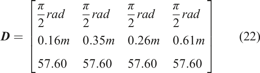


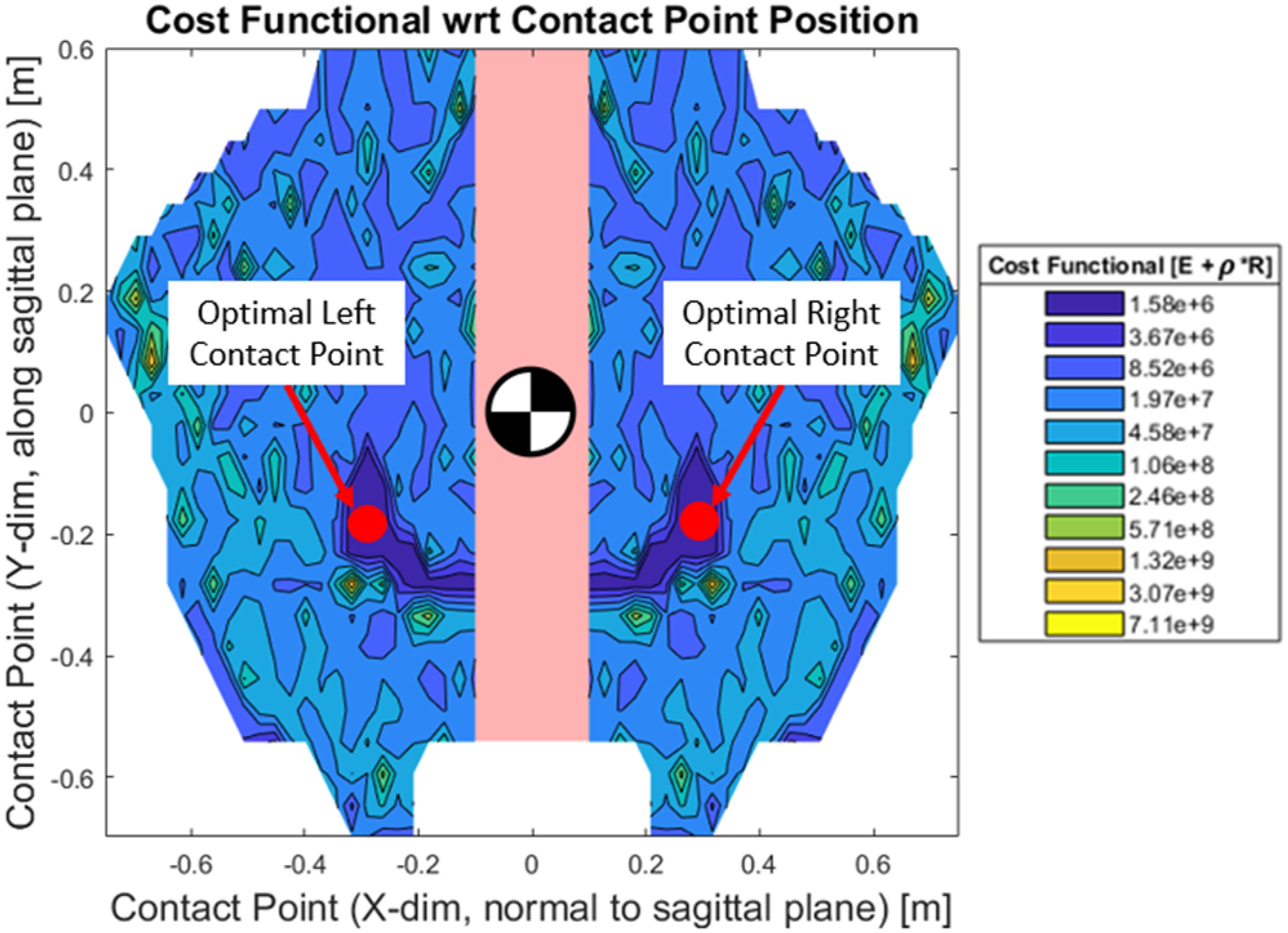
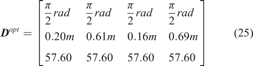
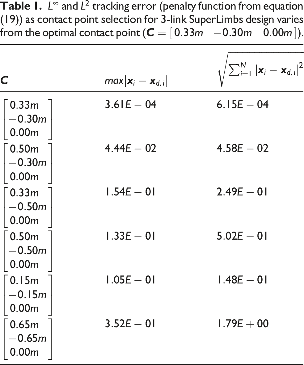
We began the full parameter sweep by analyzing the grid of localized link lengths, relative to the optimal coarse-grid link lengths in equation (22), as shown in Figure 9. Once the optimal localized link length combination is found, the optimal intrinsic design parameters from equation (22) is updated and fed into the next step of the algorithm, where the grid of localized contact points is explored, as shown in Figure 10. Figures 9 and 10 represent the final step of the fine-grid localized optimization via exhaustive parameter sweep, where the red circle represents the final converged minima. Following the localized optimization, we found the final SuperLimbs design to be the following: Localized optimization via full parameter sweep of link lengths for SuperLimbs kinematic structure. A 3D representation of the parameter sweep is shown in the left figure (where Localized optimization via parameter sweep of contact point for SuperLimbs kinematic structure. The red points represent the global minima (the optimal contact points for both SuperLimbs). The origin represents the Center of Mass (CoM) of the astronaut body projected onto the surface. The pink region represents the astronaut body keep-out zone.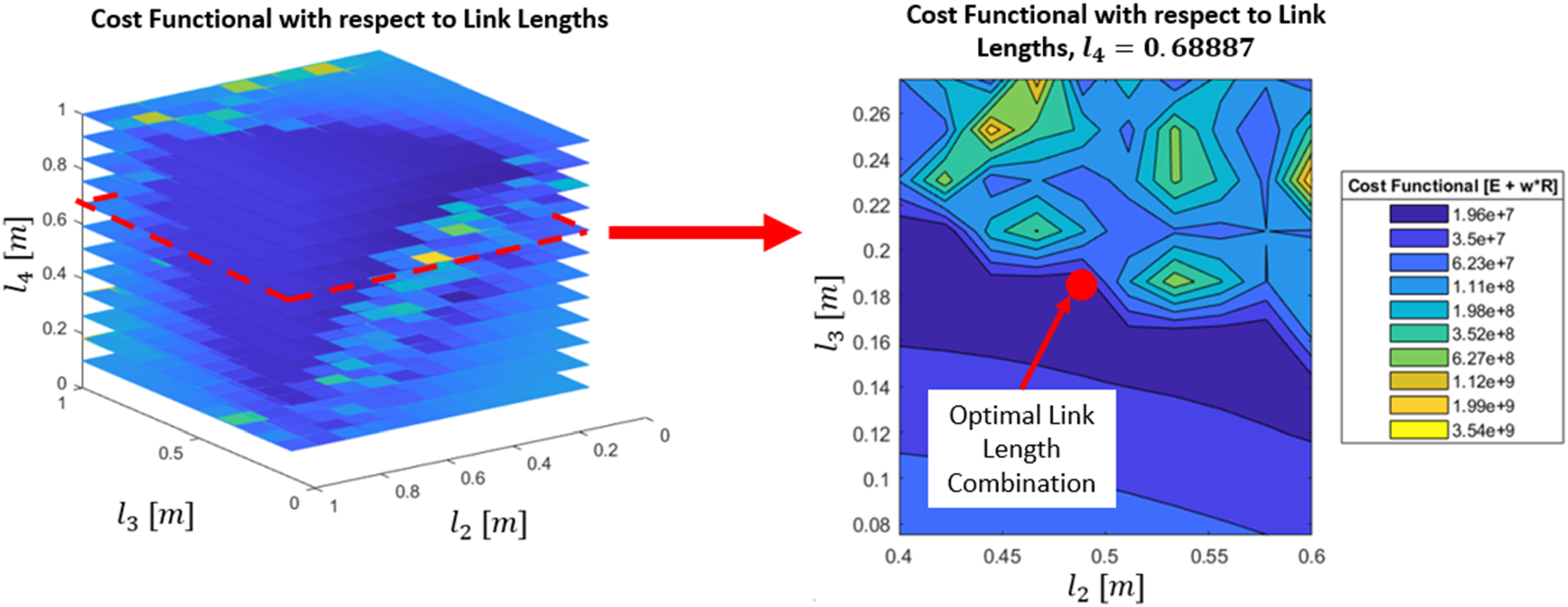


Discussion on the results and characterization of the final design
Link length proportion
By analyzing the full parameter sweep results from Figures 9 and 10, we can make a final decision on the SuperLimbs design with a detailed discussion on its impacts and implications. In order to facilitate discussion of the final SuperLimbs design, we can compartmentalize the design space at each individual parameter set. Starting with the link lengths, we can observe that the optimal point in the link length parameter space is in a region where The SuperLimbs joints are presumed to be capable of a stroke range much wider than that of human joints (where motors bear joint limits of +/− 180° and human joint limits are well below this range). This suggests that SuperLimbs have far greater dexterity/flexibility than human appendages. The link lengths
Ground contact location
Furthering this discussion, we can also analyze the full parameter sweep of the contact point with the ground, as shown in Figure 10. We can observe that a region of minima is present in an area where the SuperLimbs end-effector contacts the ground rearward of the astronaut’s CoM,
Rearward placement of the end-effectors indicates that the SuperLimbs, acting as an extra set of legs, offers effective bracing performance as it assists the astronaut to an upright standing position. Effectively, the positions of the end-effectors expand the base of support available to the astronaut. The fact that the astronaut’s CoM is shifted rearward due to the additional mass/inertia by the SSA/PLSS (Sridhar et al., 2017) implies that SuperLimbs contacting the ground rearward is a highly effective bracing strategy. As the astronaut performs a post-fall recovery, the CoM translates rearward (during the
In addition to the optimal contact point being placed rearward of the astronaut CoM, the optimal contact point is also placed close to the astronaut’s body. By keeping the contact point close to the astronaut’s body, the SuperLimbs is able to maintain a pose well within its dexterous range (Angeles and López-Cajún, 1992; Gosselin, 1992), providing a large enough stroke length to allow it the ability to follow the astronaut’s CoM with minimal tracking error.
Actuator torques
We can begin investigating the feasibility of the SuperLimbs by extracting the performance characteristics of the final selected design (
Redundancy and robustness
When analyzing torques on a 3-link design Comparison of various performance metrics between a 3-link and 4-link SuperLimbs design. Additional data can be found in the supplemental materials Figures (S)-1–(S)-2.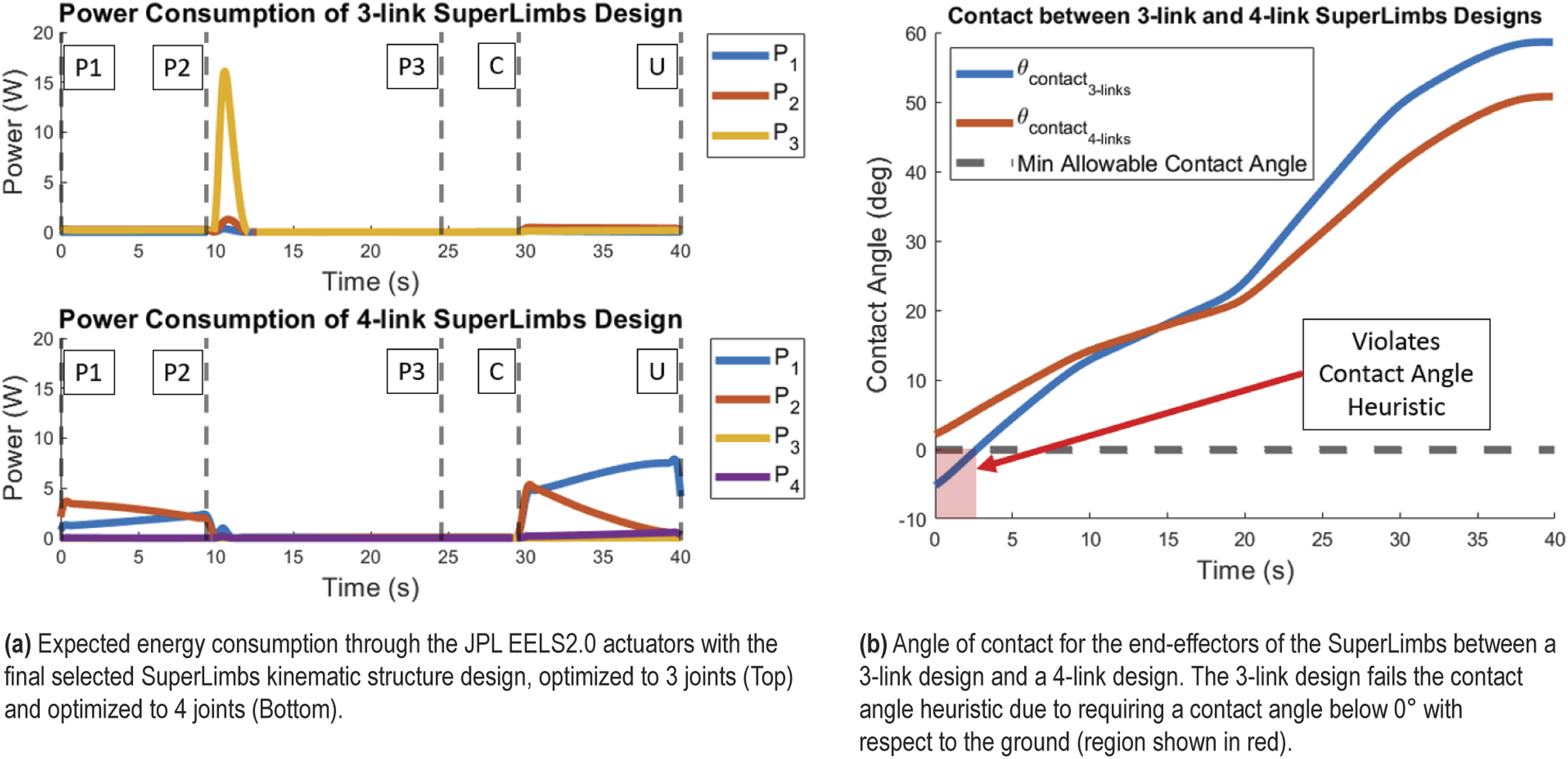
However, in order to generate a 3-link design to perform a post-fall recovery, we had to relax the “no-slip ground contact” heuristic. By relaxing the friction cone constraint, the 3-link design was required to take a pose where the end-effectors took a contact angle below 0°, which is physically implausible, as shown in Figure 11(b). To that end, we found that the expanded null space of the 4-link SuperLimbs allows for IK solutions that satisfy all of the defined functional requirements initially set. Therefore, 4 joints is the minimum required number of joints to satisfactorily develop a multi-use set of SuperLimbs.
Energy consumption
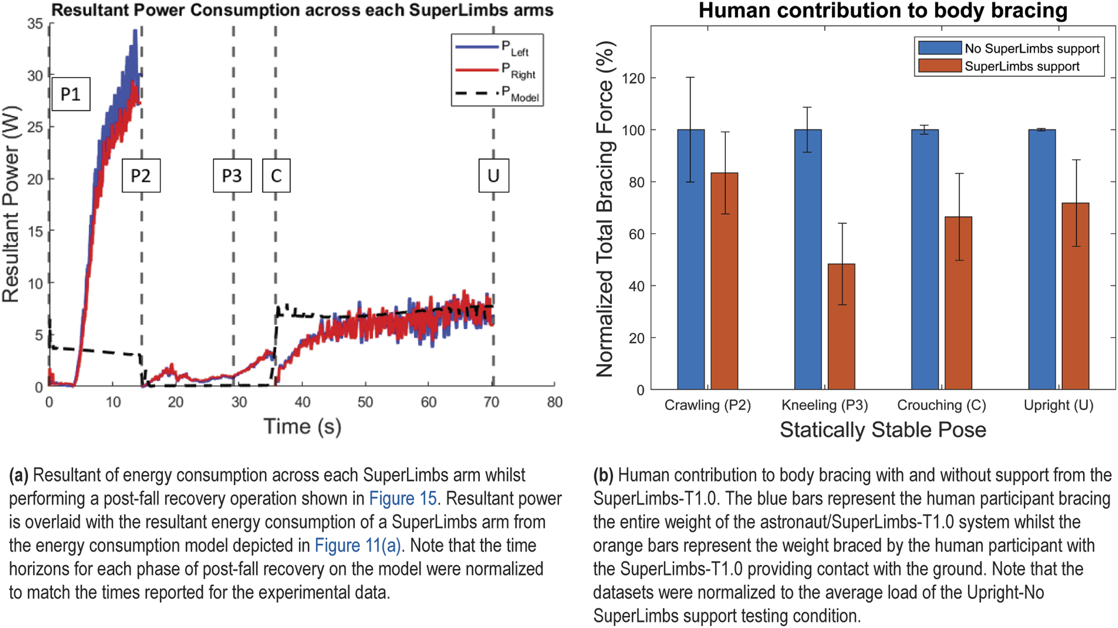
In parallel to analyzing the expected torques required by the actuators, the energy consumption through the actuators (assuming that there are no other power losses due to electromechanical inefficiencies) is also assessed to ensure the feasibility of the design. In Figure 11(a), it should be noted that the energy consumption of each of the actuators remains well below 30 W. This is due to the fact that the SuperLimbs continuously reorient their arm postures throughout the post-fall recovery trajectory to minimize energy losses. This indicates an important and distinct advantage of SuperLimbs over powered exoskeletons (Huo et al., 2016) and other wearable robots; SuperLimbs can take arbitrary postures, while exoskeletons are restricted to the same human posture. A pair of SuperLimbs can take advantage of its flexibility in kinematic structure to support loads that minimize energy consumption, leading toward smaller batteries and a compact body.
Furthermore, by investigating the energy consumption during the recovery phases
When assessing the energy consumption of the 3-link design variant, we found a total energy loss of 29 J. Concurrently, the 4-link design variant was found to have a total energy loss of 135 J. Due to the lack of redundancy in the 3-link design, the SuperLimbs took a nearly singular pose throughout the trajectory of the post-fall recovery, which provided significant reductions in energy consumption (by means of bearing the load through the kinematic structure rather than the joints).
Internal loads/stresses
Finally, we perform structural analysis estimating stress and shear loads across the linkages, respectively. As shown in the supplemental materials of this article, the normal loads and the shear loads through the SuperLimbs links are calculated; see supplemental materials Figure (S)-2. Compressive loads and shear loads are observed across the SuperLimbs’ linkages, particularly during the P1
Development of SuperLimbs Terran-class prototype
An optimal design of the SuperLimbs has been determined through the two-phase design optimization process. This design, although optimized for the performance metrics defined earlier, must be evaluated to ensure that structurally/functionally the optimal design is feasible. To this end, prototype SuperLimbs usable for various tests under Earth’s gravity have been fabricated. This particular prototype is dubbed the “SuperLimbs-T1.0,” where the “T” stands for “Terran” or Earth. This prototype will not only be used to validate the effectiveness of post-fall recovery, but will also be used as a testbed to explore various EVA use case scenarios for continued SuperLimbs development.
Description of final realized design
Figure 12(a) shows a Computer-Aided Design (CAD) rendering of the SuperLimbs-T1.0 prototype, with kinematic properties described by equations (25)–(27). Each SuperLimb, as described earlier, contains 4 actuators powered by JPL EELS2.0 actuators. The base actuator (joint 1) is secured to an A-Frame style mounting box that is housed underneath an extruded aluminum frame backpack that simulates the PLSS 2.0 (Graziosi et al., 2016). Each linkage consists of merely tube-shaped geometries with the exception at joint 4, where a corner bracket geometry was adopted to realize the optimal link lengths and joint orientations, as well as to satisfy the structural strength requirements based on the stress analysis. SuperLimbs-T1.0 prototype design overview.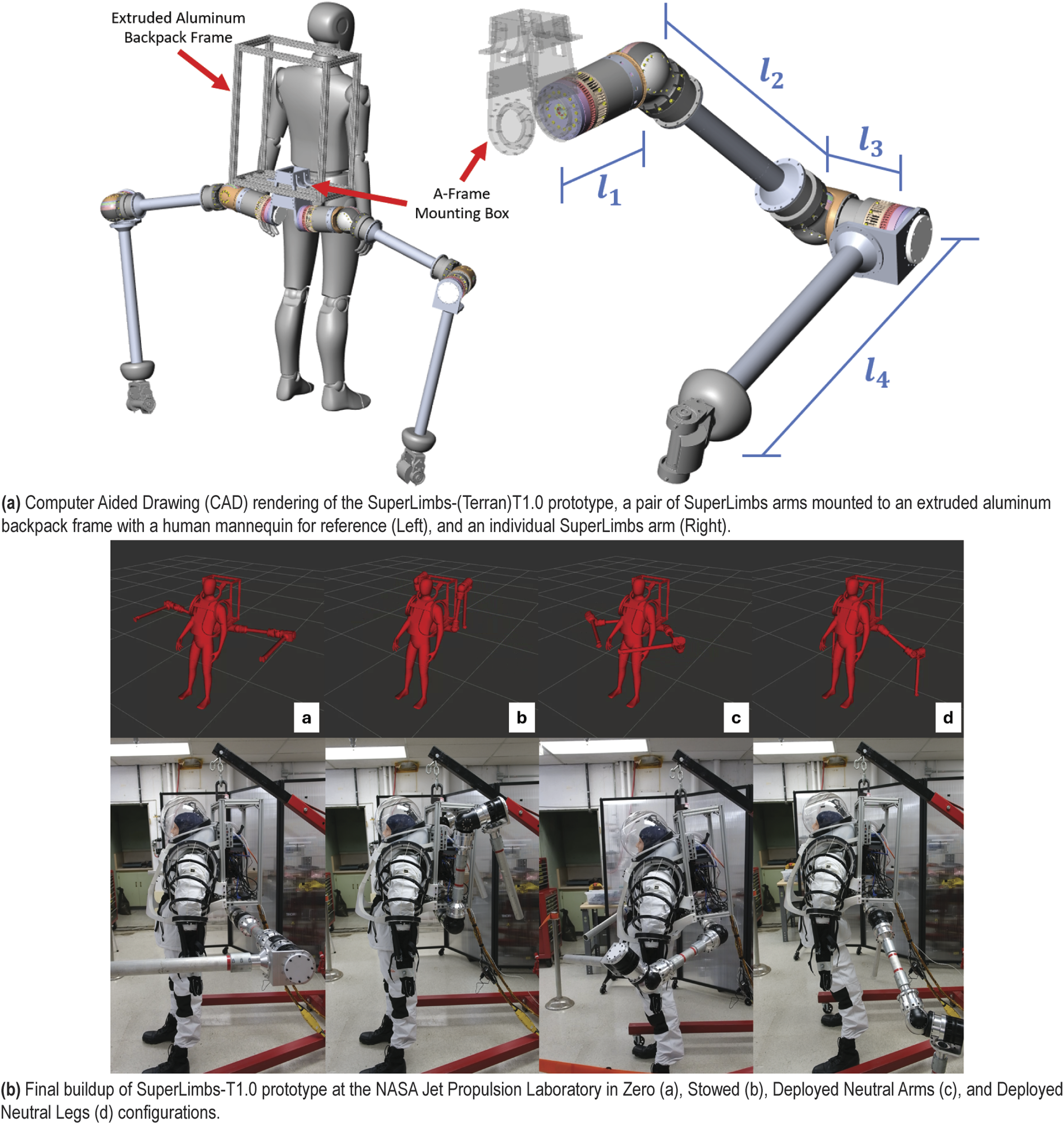
Final developed prototype
The final SuperLimbs-T1.0 prototype was developed in-house at the NASA Jet Propulsion Laboratory (JPL) in cooperation with the Robotic Mobility & Manipulation Section (358). Figure 12(b) shows a mannequin in a simulated space suit wearing the SuperLimbs-T1.0 prototype.
This prototype will serve as the primary testbed for evaluating and demonstrating control paradigms for SuperLimbs to assist astronauts in partial-gravity EVAs. In particular, this prototype enables control design demonstrations in a controlled/earth-based environment and also investigates physical designs for eventual flight hardware (SuperLimbs-(Lunar)L and SuperLimbs-(Martian)M). The current variant of the SuperLimbs-T1.0 platform is powered via off-board power supplies at a rated potential of 70 V which is delivered with use of an insulated umbilical cable harness.
Control pipeline of final developed prototype
Each of the JPL EELS2.0 actuators used on the SuperLimbs-T1.0 prototype are outfitted with an ELMO Platinum Twitter driver that bears a customized carrier breakout board to parse power, BLDC phases, and EtherCAT telemetry throughout the robotic system. The drivers are controlled using a modification of an in-house JPL-internal control framework known as Controls and Autonomy for Sample Acquisition and Handling (CASAH) (Edelberg et al., 2018). CASAH is a robust and adaptable control framework centered around experimental actuators driven using ELMO drivers via EtherCAT.
In the context of robotic control, SuperLimbs must be treated as separate independent manipulators with send/receive telemetry. To this end, each SuperLimbs arm is assigned as an independent EtherCAT branch, enabling discrete address assignment and the capability to add additional SuperLimbs arms to the control architecture, as shown in Figure 13(a). A Next-Unit of Computing (NUC) small form-factor computer connected within the backpack frame acts as the EtherCAT leader and ROS2 high-level controller. SuperLimbs-T1.0 drivers communication and control architectures. Note that the EELS2.0 actuators on the SuperLimbs-T1.0 operate from ELMO Twitter Platinum drivers connected in series (with each arm connected in parallel) that are controlled over a modified Controls and Autonomy for Sample Acquisition and Handling (CASAH) framework.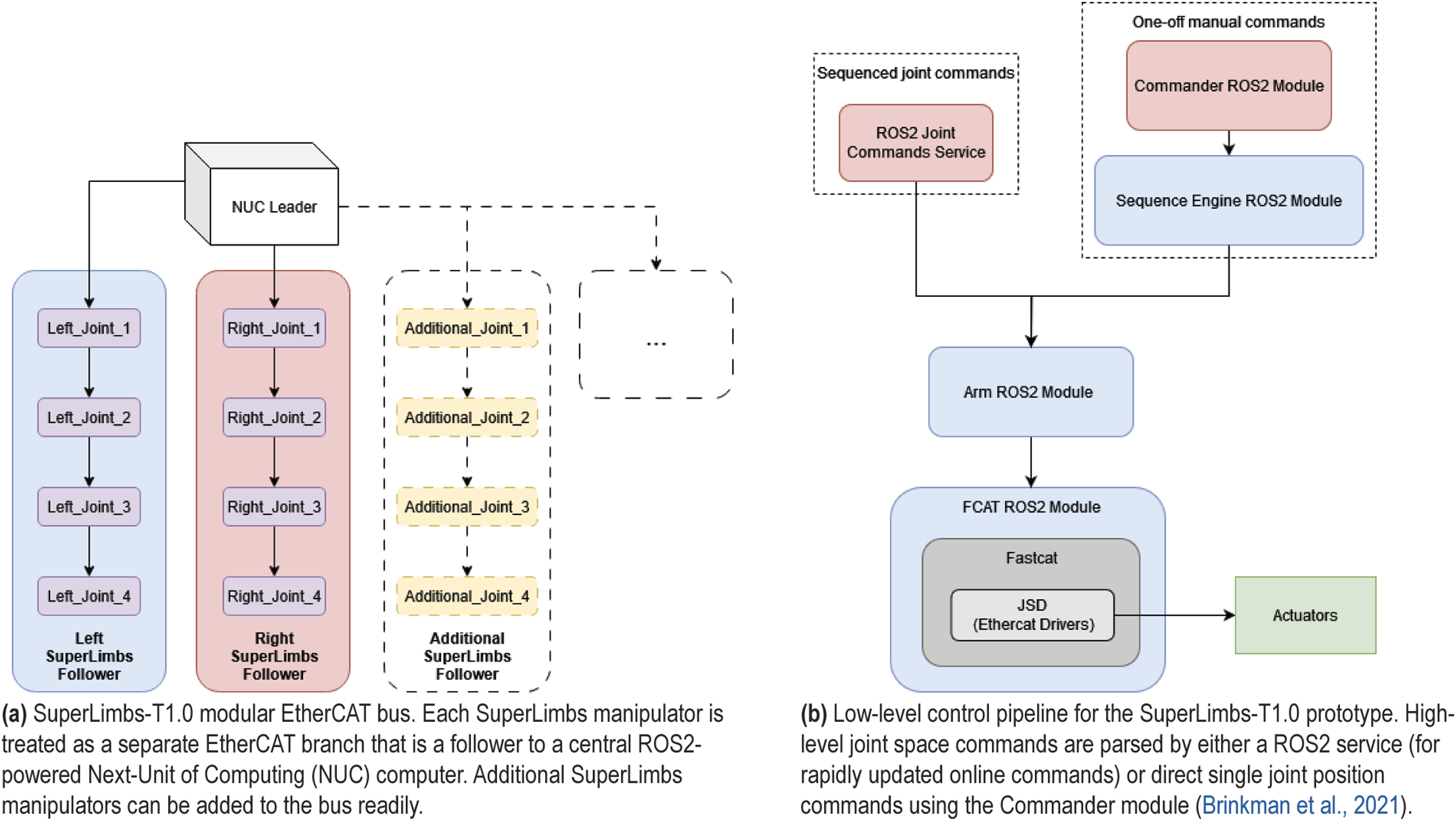
The actuator-level control of the SuperLimbs-T1.0 prototype is handled using a ROS2 wrapper of the Just SOEM Drivers (JSD) library, which drive communication to devices on the EtherCAT bus, as depicted in Figure 13(b) (Brinkman et al., 2021).
The modified CASAH framework provides a low-level command module that can accept high-level joint space commands from more sophisticated control architectures, such as impedance control, admittance control, etc. Joint space commands, provided by a high-level controller, are fed into a ROS2 service that then parses into the Arm module. The Arm module then interpolates the provided joint space commands and performs preemptive collision checking. Once the command is sent to the FCAT module, Arm performs online collision checking.
Experimental validation of SuperLimbs prototype
Provided a completed assembly of the SuperLimbs-T1.0 prototype, we performed validation tests to evaluate the effectiveness of the derived SuperLimbs design by using a mannequin. For this experiment, we analyzed the following attributes: (1) Post-Fall Recovery Success: Ability for the SuperLimbs-T1.0 to perform a post-fall recovery with a 155 N human mannequin load under Earth’s gravity. Note that the weight of a human (90 kg) on the surface of the moon produces 146 N of load, allowing the weight of the mannequin to emulate that of an astronaut on the moon. (2) Power Consumption: The power consumption through each of the actuators by means of measuring the current with respect to time throughout the post-fall recovery operation. (3) Load Bearing Capacity: The endpoint forces exerted by both manipulator arms to catalog the loading required to lift the human mannequin under Earth gravity.
The testing apparatus consists of orienting a nursing training mannequin into a Prone (P1) configuration with an overhead hoist that is set to a height slightly above the space suit cuirass touching the floor. Throughout the operation of the post-fall recovery, the hoist is adjusted merely to prevent the mannequin from falling forward or rearward, so the SuperLimbs-T1.0 is performing all of the work to lift the mannequin body. The bottom of the boots, where the balls of the feet are located, are bolted into a tube that is mounted to an extruded aluminum platform; which enables rotational motion and prevents translational motion of the feet. The testing setup is shown in Figure 14. Experimental setup to evaluate the effectiveness of the SuperLimbs-T1.0 prototype performing a post-fall recovery.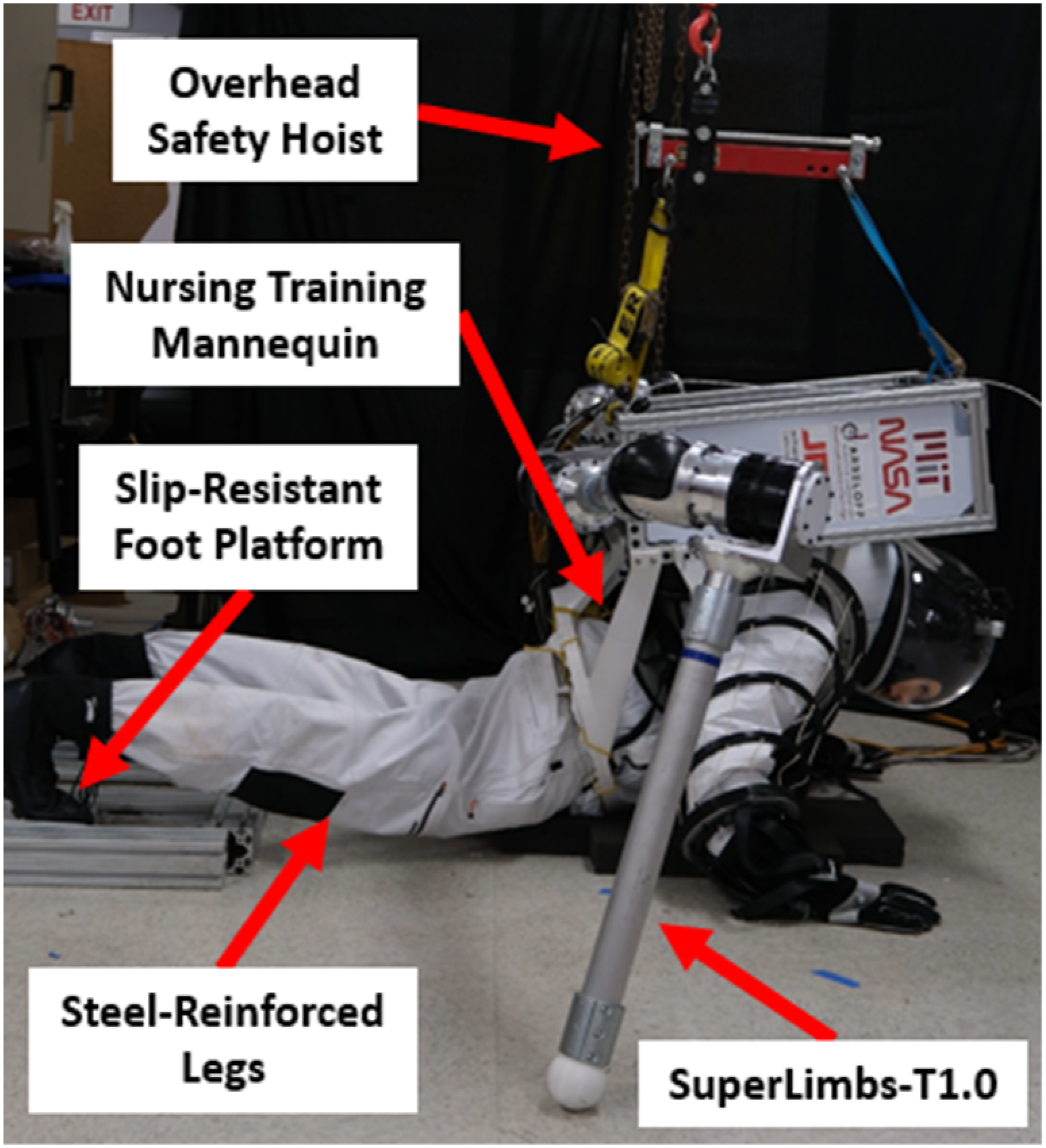
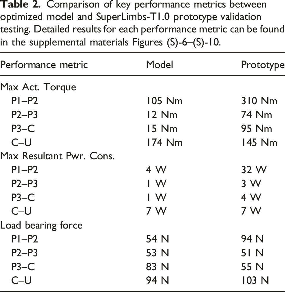
Comparison of key performance metrics between optimized model and SuperLimbs-T1.0 prototype validation testing. Detailed results for each performance metric can be found in the supplemental materials Figures (S)-6–(S)-10.
Post-fall recovery success
To measure the success of Post-Fall Recovery, we used direct observation of the forces supplied by the SuperLimbs-T1.0 prototype to move the mannequin from a Prone (P1) to an Upright (U) configuration. For this experiment, a modified trajectory was utilized that first moved the mannequin/SuperLimbs’ CoM from a Prone (P1) to a Crawling (P2) configuration. Additionally, the knee and hip joints of the mannequin were reinforced with spring steel to maintain upright stability of the mannequin/SuperLimbs system during the Prone (P1) to Crawling (P2) phase of recovery. The spring steel reinforcement on the legs of the mannequin were then removed to allow the mannequin/SuperLimbs’ CoM to properly move from P2 to Kneeling (P3). Following the P3 configuration, the SuperLimbs-T1.0 was then commanded to shift the mannequin/SuperLimbs’ CoM into a Crouching (C) configuration. Finally, the robot was commanded to move the mannequin/SuperLimbs’ CoM vertically to reach an Upright (U) final configuration, as shown in Figure 15. View the supplemental material video for the post-fall recovery success. Post-Fall Recovery demonstration showing the SuperLimbs-T1.0 prototype carrying a human mannequin through the 4 phases of recovery, starting from a Prone (P1) position, transitioning to Crawling (P2) [i–iii], then Kneeling (P3) [iii–iv], then Crouching (C) [iv–v], and finally arising to an Upright (U) position [v–vii].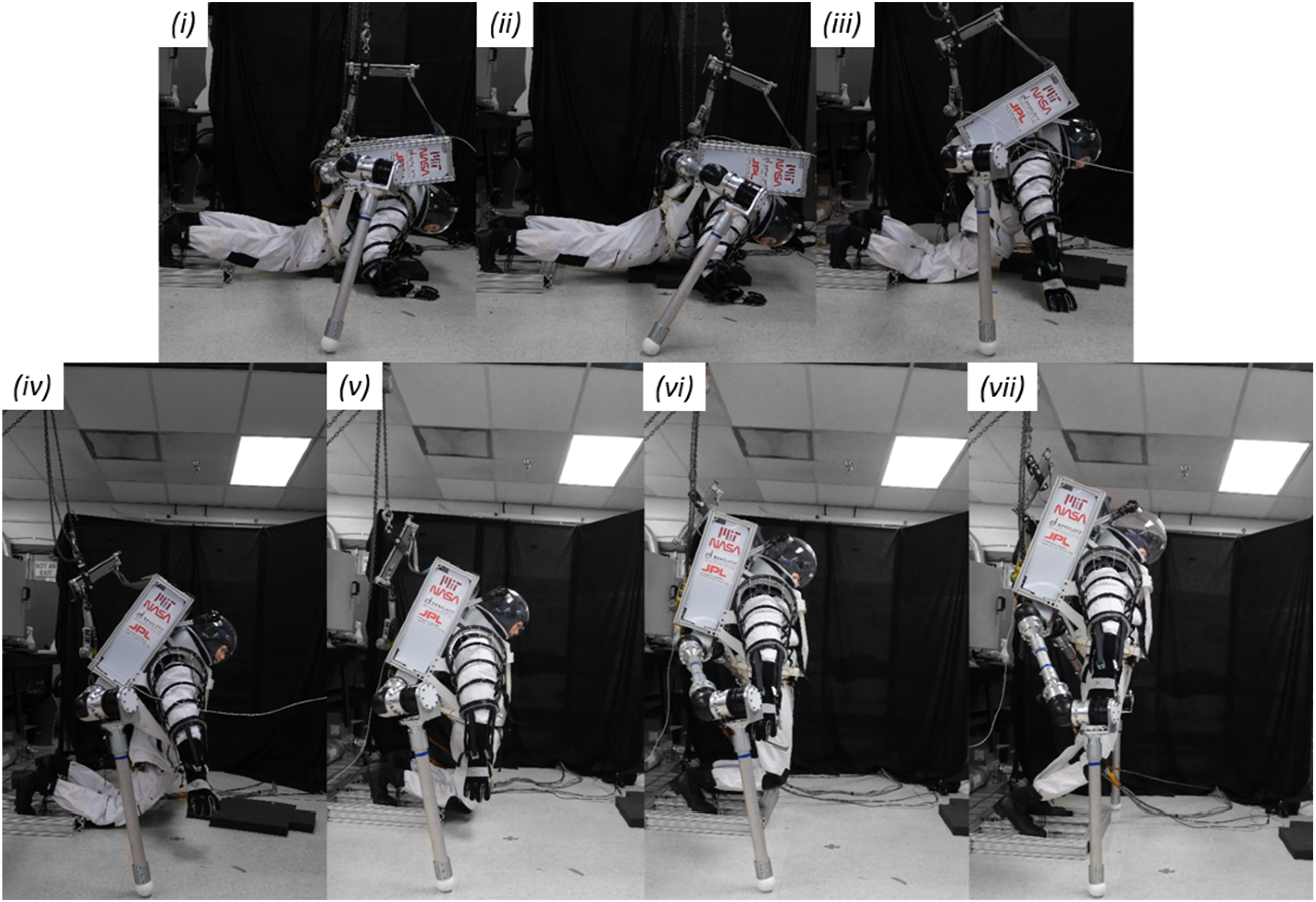
Energy consumption
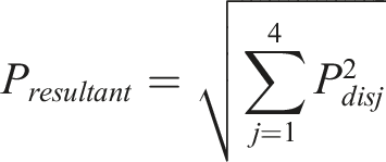
The current draw through each of the actuators were saved using a rosbag package that captured all of the telemetry data as ROS2 messages. Using the torque constant ( Measured experimental data from both the mannequin post-fall recovery experiment and human body bracing experiment. Additional data and analysis from both experiments can be found in the supplemental materials (Figures (S)-6–(S)-10 for mannequin post-fall recovery experiment and Figures (S)-11–(S)-17 for human body bracing experiment).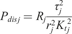
Load bearing capacity
Load bearing forces were derived from extracting both the current draw and angular position measurements from each of the actuators. Given the pose of the SuperLimbs-T1.0 (captured from the angular position measurements) and the fact that the joint motion is quasi-static for the post-fall recovery demonstration, the task-space forces can be found based on the Jacobian
The load bearing forces throughout the post-fall recovery demonstration are shown in the supplemental materials Figures (S)-9–(S)-10. Given a passive mannequin, incapable of providing any contribution to performing a post-fall recovery, the SuperLimbs-T1.0 bore the entire load of the mannequin/SuperLimbs-T1.0 mass throughout the trajectory, which is a significantly higher load than what was used on the model, as shown in Figure 6(b).
Human body bracing
A preliminary human study was performed that evaluated the effectiveness of the SuperLimbs-T1.0 offloading the weight of the combined astronaut/SuperLimbs system. A human participant was asked to don the SuperLimbs-T1.0 and take on a set of statically stable poses defined throughout the post-fall recovery trajectory. The test participant would brace the weight of the SuperLimbs-T1.0 with and without the robot providing any contact with the ground.
All contact points from the human and SuperLimbs were in contact with weight scales to measure the human contribution to body bracing. Each testing condition was performed over repeated trials with descriptive statistical data provided in the supplemental materials. Further details from the human body bracing experiment can also be found in the supplemental materials. All human studies are conducted under the protocol approved by the Massachusetts Institute of Technology Committee on the Use of Humans as Experimental Subjects, protocol number 2306001022. For safety purposes compliant to the human participant protocol, the SuperLimbs-T1.0 would not be powered but were fixed mechanically while the human is wearing the system.
The comparison between the pure human body bracing and assisted body bracing is shown in Figure 16(b).
Discussion of results between experimentation and modeling
By analysis of Table 2 and Figures 15, 16(a), and 16(b), we can make the following observations: Actuator torques and load bearing forces were considerably higher during the P1–P2 phase of post-fall recovery for the prototype experiment. This is in part due to the fact that the mannequin used lacks any ability to provide contribution for the post-fall recovery, requiring the SuperLimbs-T1.0 to provide all of the force necessary. Single actuators consumed relatively higher energy than the rest for the prototype experiments. This is in large due to the modified trajectory adopted for the experiments. Due to the lack of stiffness control on the mannequin’s joints, an iterative process had to be adopted to determine a joint trajectory appropriate to perform the post-fall recovery. To this end, we chose to use as few actuators as possible to move the mannequin/SuperLimbs-T1.0 CoM between the phases of recovery. This led to actuators bearing more of the load to carry out the motion and thus resulting in higher measured actuator torques. The SuperLimbs-T1.0 successfully performed a post-fall recovery, despite using a non-stiff mannequin. Although the mannequin lacked the ability to contribute to load bearing, the SuperLimbs-T1.0 was still able to carry out the post-fall recovery operation while operating within the operating limits of the JPL EELS2.0 actuators. However, it should be noted that if human testing were to occur, the trajectory used in the optimization model would need to be adopted so as to not place all of the load required for motion into a few select actuators, like in the modified joint trajectory used for these experiments. The SuperLimbs-T1.0 aided in reducing the weight braced by the astronaut wearer. With a human in-the-loop, the kinematic structure of the SuperLimbs-T1.0 prototype provided a measurable reduction in the total load borne by the human participant. With bracing support from the SuperLimbs-T1.0, the human load contribution was reduced by nearly 55% (for the Kneeling (P3) statically stable pose).
Conclusion
This paper established a foundation for the design methodology for a set of wearable robotics, known as SuperLimbs. Since SuperLimbs present a highly unconstrained design space, one must adopt a “learn-first, design-later” approach, where the task to be augmented must be well understood (in particular, ergonomics) and contextualized in a way that justifies the use of robotic augmentation. Designs can be evaluated based off human studies in a variety of ways. For our study, we chose to use a human voluntary joint torque model in combination with a static bracing and space suit stiffness model to determine where in a post-fall recovery trajectory a set of SuperLimbs needs to provide assistance to the astronaut wearer. Quantifying the torque gaps allowed us to generate the required forces required from SuperLimbs and the astronaut anthropometric model provided us with the trajectory for SuperLimbs to take. Both the required forces and trajectory derived from these models were used to evaluate possible SuperLimbs kinematic designs.
Use of an AI searcher in combination with a localized exhaustive search optimization enabled us to effectively down-select design combinations (in terms of key kinematic parameters) to practical/valid designs. A total of 5.4 million design permutations were down-selected to 252 permutations (based off constraints presented by discoveries during in-house ergonomics studies and human spaceflight requirements). From those 252 permutations, a final design, which performed best in minimizing energy dissipation through the actuators while also minimizing tracking error, was selected. Expected loads through the design were then extracted and leveraged as evaluation data for a more extensive design analysis (in our case FEA) to validate the design (full-fidelity CAD model implementing kinematic parameters of the selected design). Upon validation of the final selected design, a full-scale/earth-based prototype of the SuperLimbs was developed that is capable of performing demonstrations and verifications of control paradigms and follow-up studies to further mature the feasibility and raise the Technology Readiness Level (TRL) of SuperLimbs in astronaut EVA applications.
Limitations
Human modeling
Concerning the human modeling that governed the design philosophy of the SuperLimbs, the following limitations must be taken heed of: Use of a mathematical human voluntary torque model: The Anderson model, although a well cited and heavily utilized mathematical model in the human biomechanics field, is subjected to inaccuracies due to errors with the measurement equipment which derived the mathematical parameters, as investigated thoroughly in Haering et al. (2019). Symmetry about the sagittal plane for Post-Fall Recoveries assumption: The post-fall recovery model leans on assuming symmetrical motion about the sagittal plane. Although prior human biomechanics studies have found that human motion is symmetric about the sagittal plane in sit-to-stand trajectories, as shown in Gilleard et al. (2008), Rosa et al. (2022), and VanSant (1988) found that about 25% of their subject pool took non-symmetric motion about the sagittal plane when performing a supine-to-stand recovery. From Ballesteros et al. (2024), symmetric motion about the sagittal plane was discovered for prone-to-stand recovery, however the sample size was low (N = 4). Neglecting the S1
Design down-selection methodology
The down-selection process of the feature tree for intrinsic design parameters was limited due to the availability of actuator hardware. Use of the JPL EELS2.0 actuators fixed the motor gear ratio,
Experimental setup
Due to the unique application of SuperLimbs, there were several limiting factors that must be considered in future works: Operating under Earth Gravity: The use of SuperLimbs for astronaut augmentation is to be considered for Lunar and Martian environments. Due to an inability to access both of these environments at this time, post-fall recoveries had to be performed against Earth gravity, where inertial effects of the human body are considerably different. Operating at a 70 V electric potential: The actuators used for the prototype, JPL EELS2.0, are operated at 70 V DC. For complete human subject tests, an additional safety measure must be implemented. Use of a mannequin over a human testing participant for the post-fall recovery experiment: Without an active human test subject, voluntary joint torques to aid and better reflect the human contribution to the post-fall recovery were lacking. During testing, the joint trajectory optimized for post-fall recovery was implausible to conduct with a passive mannequin, forcing the mannequin/SuperLimbs-T1.0 CoM to take a different trajectory. Additionally, the mannequin and the experimental setup had to be modified to maintain stability of the mannequin/SuperLimbs (removal of spring steel after the Prone (P1) to Crawling (P2) phase and repeated attempts of timing the overhead hoist to support stability during the Crouch (C) to Upright (U) phase), leading to abrupt pauses in the demonstration. Operating in an enclosed laboratory space: Partial-Gravity EVAs are to occur on the surface of either the Moon or Mars, which presents an unstructured environment with varying levels of surface quality. The presence of fine sand-like regolith presents a challenging surface to place robotic grippers against. The laboratory space for these experiments is a flat/non-granular surface, counter to that of an actual Partial-Gravity EVA. Use of off-board power over on-board batteries: SuperLimbs is designed with the intent of being a part of a mobile space suit platform for long-duration EVAs. The SuperLimbs-T1.0 prototype requires use of an umbilical cable harness that siphons power from off-board power supplies. Use of off-board power first removes the use of on-board batteries (which can significantly contribute to the mass/inertia properties of the astronaut/SSA/PLSS/SuperLimbs system) as well as adds a constraint to the mobility of the testing platform (since the range of mobility is limited by the placement/length of the umbilical cable). Use of a single human testing participant for the body bracing experiment: With a single human test participant, only descriptive statistics (calculated means and standard deviations) can be provided to determine the reduction in body bracing load provided by the SuperLimbs-T1.0 support. With multiple human participants, a paired t-test can be used to more concretely assess statistical significance.
Future work
Future work will include developing gripper mechanisms to address various modes of use cases for partial-gravity EVAs (such as grippers for bracing with a regolith surface, grasping objects, etc.). Other work will include use of a higher fidelity testing environment, where the inertial effects of a reduced gravity environment can be realized, such as the Active Response Gravity Offload System (ARGOS) at the NASA Johnson Space Center (Orr et al., 2022). In combination with the reduced gravity simulator, the surface is to replicate a Lunar/Martian-type unstructured surface, where regolith, rocks, and other non-uniform features are present. Additional work will focus on certifying the SuperLimbs-T1.0 to be used with human test subjects and promote human-robot interaction confidence with close-proximity operations. Using the current actuators, JPL EELS2.0, the SuperLimbs-T1.0 will be certified to conduct human subject testing in low-load bearing tasks (such as bracing, balancing, and external materials handling) at a 28 V operating electric potential. The high voltage restriction can be removed by changing the actuator winding conditions for low voltage operation or by isolating the actuators and drivers completely from the human, which is our future work.
Future work will also include replacing the power delivery from off-board power supplies to on-board batteries to better reflect the final hardware intention.
Integration of SuperLimbs onto next-generation space suit platforms
Following the demonstration of the effectiveness of the SuperLimbs-T1.0 prototype, future work will be placed on maturing the design to meet flight requirements (Kovich, 2024; Polk et al., 2020) and integration challenges posed by modern space suit platforms. As mentioned earlier, one of the key limitations of the SuperLimbs-T1.0 prototype is the high mass. Fortunately, for Lunar and Martian EVAs, the torque requirements to brace and perform a post-fall recovery are considerably less than that on Earth; thus, future designs can choose scaled-down actuators and linkages to reduce the overall mass. With a smaller mass comes smaller form-factor actuators, opening up a wide range of integration possibilities for packaging and deployment. To maintain the design philosophy within NASA engineering, SuperLimbs can be adapted to mimic legacy hardware, such as the Simplified Aid For EVA Rescue (SAFER) system (Meade, 1995).
A Lunar or Martian variant of the SuperLimbs, given smaller form-factor actuators, can be housed in a modular attachment block that can be readily installed/removed from underneath the PLSS, as depicted in Figure 17. The attachment block can house both the on-board computer and batteries to operate the SuperLimbs, while the SuperLimbs manipulators can be folded into a tight configuration allowing for easy stowage. Integration of SuperLimbs onto modern Space Suit Platforms. Future flight-like variants of the SuperLimbs can be housed as an attachment underneath the PLSS.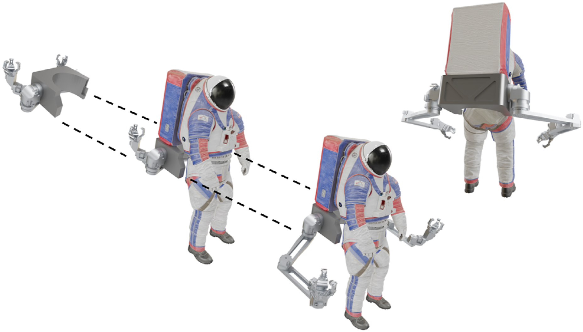
Supplemental material
Supplemental Material - Design of supernumerary robotic limbs for the augmentation of astronauts performing partial-gravity extra-vehicular activities (EVAs)
Supplemental Material for Design of supernumerary robotic limbs for the augmentation of astronauts performing partial-gravity extra-vehicular activities (EVAs) by Erik Ballesteros, Preston Rogers, Justin Jenkins, Kalind Carpenter, and H. Harry Asada in The International Journal of Robotics Research
Footnotes
Acknowledgments
The authors would like to thank Matthew Gildner, John Koehler, and Joseph Bowkett from the JPL Robotic Mobility & Manipulation Section (358) for their expertise and assistance in realizing the physical manifestation of the SuperLimbs-T1.0 prototype.
Funding
The authors disclosed receipt of the following financial support for the research, authorship, and/or publication of this article: This work was funded under the NASA Space Technology Graduate Research Opportunity (NSTGRO) Fellowship (Grant No. 80NSSC23K1207).
Declaration of conflicting interests
The authors declared no potential conflicts of interest with respect to the research, authorship, and/or publication of this article.
Supplemental material
Supplemental material for this article is available online.
References
Supplementary Material
Please find the following supplemental material available below.
For Open Access articles published under a Creative Commons License, all supplemental material carries the same license as the article it is associated with.
For non-Open Access articles published, all supplemental material carries a non-exclusive license, and permission requests for re-use of supplemental material or any part of supplemental material shall be sent directly to the copyright owner as specified in the copyright notice associated with the article.