
Abstract
Manual lifting tasks involve repetitive raising, holding and stacking movements with heavy objects. These arm movements are notable risk factors for muscle pain, fatigue, and musculoskeletal disorders in workers. An upper-limb wearable robot, as a 6-DOF dual-arm exoskeleton, which was designed to augment workers’ strength and minimize muscular activation in the arm during repetitive lifting tasks. To adjust the robot joint trajectory, the user needs to apply an interactive torque to operate the robot during lifting tasks when a standard virtual mechanical impedance control structure is used. To reduce overshooting of the interactive torque on the user’s joint, a three-tier hierarchical control structure was developed for the robot in this study. At the highest level, a human arm movement detection module is used to detect the user’s arm motion according to the surface electromyography signals. Then, a Hammerstein adaptive virtual mechanical impedance controller is used at the middle level to reduce overshooting and yield an acceptable value of torque for the user’s elbow joint in actual lifting tasks. At the lowest level, the actuator controller on each joint of the robot controls the robot to complete lifting tasks. Several experiments were conducted, and the results showed that the interactive torque on the user’s elbow was limited and the muscular activations of erector spinae and biceps brachii muscles were effectively decreased. The proposed scheme prevents potential harm to the user due to excessive interactive torque on the human elbow joint, such as related muscle fatigue and joint injuries.
Keywords
Introduction
For repetitive movements in high-frequency operations, the manual lifting of objects consumes a large amount of body energy and has low efficiency. 1 Moreover, the continuous repetition of arm movements without long-term recovery is biomechanically challenging and is associated with a risk of musculoskeletal disorders. 2 Hence, upper-limb wearable robots have been designed to enhance humans’ power when carrying heavy loads. At present, the assistance provided by these devices can be exploited to augment the performance of workers in production facilities, enhancing their endurance or strength and reducing their muscle activity. 3,4 Typical upper-limb wearable robots use tools that generate either active assistance, such as motors and pneumatic muscle actuators, or passive assistance, such as springs. 5 –8 Most devices mimic the human arm as linkages and offload weight of heavy objects from human arms to the haunch or back during robot-assisted lifting tasks. To complete the tasks, the user and the robot communicate by physical interaction, such as interactive forces or torques. 9 Interactive torques are critical variables for ensuring the safety of the user in physical human−robot interaction scenarios. 10 A small interactive torque is beneficial for decreasing the contact force and the distributed load on the user’s arm. 11,12 For an upper-limb wearable robot, interactive torques applied to the joints of the user’s arm are generated by the contact force between the user and the mechanical structure of the robot during operation.
Generally, two main methods are utilized for controlling the interactive torque in upper-limb wearable robots. One common method is to control the impact force directly with a force/torque feedback control structure. 13 Force/torque sensors must be integrated into the end-effectors or joints of the robot and measure the interactive forces and torques between the user and the robot. Another method is the virtual mechanical impedance control method. 7,8 The physical interaction model between the user and the robot is linearized into a standard impedance model that includes springs and dampers. The interactive torque is adjusted by changing the stiffness and damping parameters. 14
The control methods have been assessed in terms of performance using a force sensor to measure the actual interactive forces between the user and the robot. However, the force overshot the accepted value by more than 20 N in robot-assisted transport work and by approximately 70 N in robot-assisted lifting work. 15,16 Considering the elbow-grip length of the adult men (age range: 18–60 years, percentage: 95%), 17 the interactive torque in robot-assisted arm movement was approximately 18.06 Nm on the joint of the human elbow. As a comparison, the elbow joint applies less than 2 Nm in natural arm movements without robot assistance. 18 Therefore, it is too idealized to minimize the interactive torque in robot-assisted lifting tasks using the control methods mentioned above. In addition, depending on the effect of a long-term lifting task, the fatigued arm muscle results in a change in the dynamic parameters of the user’s arm. Fatigue also adds some disturbance in the dynamic model of the human–robot system because of the irregular movement of the user’s arm. 18 For the human–robot system, the parameters of the dynamic model are nonlinearly time varying and the standard impedance model is not highly precise for describing physical interaction in robot-assisted lifting tasks.
In addition, mechanical injuries are serious possible consequences caused by the irregular arm movements by the user. 19,20 For robot-assisted lifting tasks, the user’s arm movements should be detected during physical interaction process. 21 Biological signals, such as surface electromyography (sEMG) signals, have been used to build arm musculoskeletal models that recognize the user’s arm movement intent in an exoskeleton system. For instance, four arm muscles were utilized to develop a reference musculoskeletal model of the human upper limb, and the sEMG signals were used to control a two degrees of freedom (DOF) upper-limb exoskeleton to match the operator’s movement behavior. 4,22 However, the model is not accurate in matching the user’s arm movement in robot-assisted lifting tasks, because it does not consider movements in which a user catches a heavy object in his or her arms. 23,24 Hence, the actual model is more complex, and many modeling parameters need to be identified. 25,26
To simplify the actual musculoskeletal model, an artificial neural network (ANN) is suitable for representing the relationship between the muscle forces and joint angles in wearable robots. 3,27 For robot-assisted lifting tasks, the muscle strength, muscle activity, and mass of the heavy objects handled by the human (referred to as the loading mass in this article) need to be reflected in the ANN model. 28 A challenge is the selection of the inputs of the ANN model. Studies on physiological data have confirmed the affiliation of an individual’s body mass index (BMI) and muscle mass with his or her muscle strength. 29 In addition, some sEMG signal features (such as the root mean square (RMS) and mean absolute value (MAV)) have been explored to recognize hand gestures and to detect arm movements. 30 Considering that the subsequent work is to predict user’s arm movement handled with different loading mass, more features are increased and the calculation speed of ANN is affected. If the movements are abundant, the number of the sEMG channels will increase. Then, the signals between the channels are correlated and ANN is a weak tool for building the global optimal model. As an alternative method, principal component analysis (PCA) can transform the original parameters into a new set of variables that are uncorrelated with each other. 31 It plays an important role in the data-driven modeling method. 32
Six degrees of freedom upper-limb wearable robot
Our robot is designed as a humanoid structure with a back and two arms, as shown in Figure 1. The arm consists of a shoulder with 2-DOF (flexion/extension and adduction/abduction) and an elbow with 1-DOF (flexion/extension). Since the rotation center of the shoulder joint is difficult to estimate, the device can adjust the glenohumeral joint to a small extent. In addition, the spring and the leaf spring can generate tensile forces to promote adduction/abduction in the shoulder. Two pneumatic artificial muscles (PAMs) connect the forearm with the upper arm and are used to generate a large torque in the elbow joint. It should be noted that the device is attached to the user’s back by a spinal orthotics to unload the external force from the arms to the back and haunch. There are also five hook-and-loop-fasteners to attach the 6-DOF upper-limb wearable robot to the user: on the left upper arm (k), the left forearm (j), the haunch (i), the right upper arm (g), and the right forearm (h).

The 6-DOF upper-limb wearable robot. Labels from the clockwise: a: EMG electrode 1; b: heart beat monitor; c: EMG electrode 2; d: pneumatic soft sensor; e: incremental photoelectric rotary encoder (on the elbow joint); f: hook-and-loop fastener 5; g: hook-and-loop fastener 4; h: EMG electrode 3 (on the back); i: hook-and-loop fastener 3; j: hook-and-loop fastener 2; and k: hook-and-loop fastener 1. EMG: electromyography; DOF: degrees of freedom.
The sensing system of the 6-DOF upper-limb wearable robot comprises three EMG electrodes (Flex Comp Infiniti, Thought Technology Ltd, Canada): one incremental photoelectric rotary encoder (HKT30, Guangsuwei Electronic Inc., Shenzhen, China), one pneumatic soft sensor, and one heart rate monitor (H10, Polar Electro, Oulu, Finland), as shown in Figure 1. The sEMG signal measured by EMG electrode 1 is used to detect the human arm movement, while the signals measured by EMG electrodes 2 and 3 are used to evaluate the performance of the robot. The heart rate monitor records the subject’s heart rate when he or she is wearing the robot. The encoder is used to record the approximate angle of the robot’s elbow joint during movements. The pneumatic soft sensor is installed in hook-and-loop-fastener 5. The sensor is used to measure the contact force between the user’s arm and the robot during physical human–robot interactions. It is assembled by an air pad, a soft tube, and a pressure sensor, as shown in Figure 2. The air pad, which acts as a force interface, is made from silicone rubber (Dragon Skin fx-pro, Smooth-on Inc., USA). The chamber is soft and stretchable. 33 The relationship between air pressure and contact force has been established. 34 When the air pad is subjected to a contact force, the chamber becomes deformed. Since the total amount of gas remains constant after deformation of the chamber, the air pressure changes. This change can be detected by the pressure sensor. From the Clapeyron equation, the deformed volume of the chamber (V 2) can be calculated by the compressed pressure (P 2), the initial pressure (P 1), and volume (V 1), as

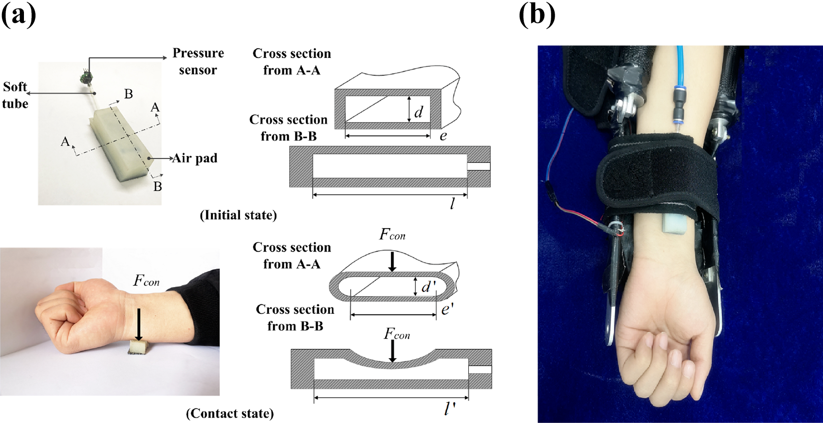
Prototype of the pneumatic soft sensor. (a) In the initial stage, the chamber of the air pad is similar to a cube, and its cross sections (A-A and B-B) are similar to rectangles. The variables e, d, and l are the width, height, and length of the chamber in the initial condition, respectively; e′, d′, and l′ are the width, height, and length of the chamber in the contact state, respectively. When the air pad is subjected to a contact force, the size of the chamber becomes deformed, resulting in a change in air pressure. (b) The installation of the pneumatic soft sensor in the 6-DOF wearable robot. DOF: degrees of freedom.
The deformation of the chamber is also depicted in Figure 2. The variables e, d, and l are the width, height, and length of the chamber in the initial condition, respectively; e′, d′, and l′ are the width, height, and length of the chamber in the contact state, respectively. From the previous study,
34
assuming the top layer of the chamber is a simply supported beam, the contact force (
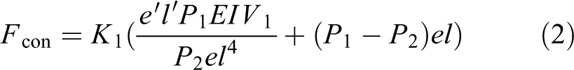
where E is the elastic modulus, I is the inertia, and K 1 is a constant coefficient.
Compared with the deformation of the chamber in the height dimension, the amount of deformation in the width and length dimensions is small (

where
Standard virtual mechanical impedance control.
The classic method of controlling interactive torque is standard virtual mechanical impedance control, as shown in Figure 3. This control scheme is based on the physical human–robot interaction model. The model represents a linear relationship between the interactive torque (Te
) and the difference in the elbow joint angle between the robot and the user (

where
The standard virtual mechanical impedance control structure.
The interactive torque is calculated by formulas (2) and (3). When M, B, and K are set as constants, formula (4) can be regarded as the second-order differential equation about

where q is the current joint angle of the robot.
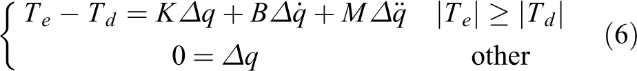
The interactive torque is used to drive the upper-limb wearable robot in lifting tasks. However, unintended movement of the user’s arm will change the interactive torque immediately and frequently in practice. Therefore, a threshold (Td ) is implemented, and formula (4) can be shown as
Safe human–robot interaction control structure for lifting tasks
Generally, the standard virtual mechanical impedance control is a classic control method that is used in upper-limb wearable robots that are used by humans to complete robot-assisted lifting tasks. As it is a linear model, the parameters of the standard virtual mechanical impedance model are set to match the actual interactive torque in the physical human–robot interaction environment. However, the muscles on the human arm will fatigue after handling different kinds of objects in a couple of minutes resulting in a change in the stiffness of the arm. In addition, research has shown that when the arm posture changes, the stiffness of the human arm needs to be identified again. 35 Hence, the parameters are time-varying and nonlinear. Moreover, the user needs to apply a contact force to the force sensor of the upper-limb wearable robot; the force then triggers the standard virtual mechanical impedance controller. The user’s arm must move before the robot moves. Therefore, the movement is unnatural. Furthermore, the human–robot interfaces of the upper-limb wearable robot are rigid and can easily cause mechanical injuries to the user’s arm.
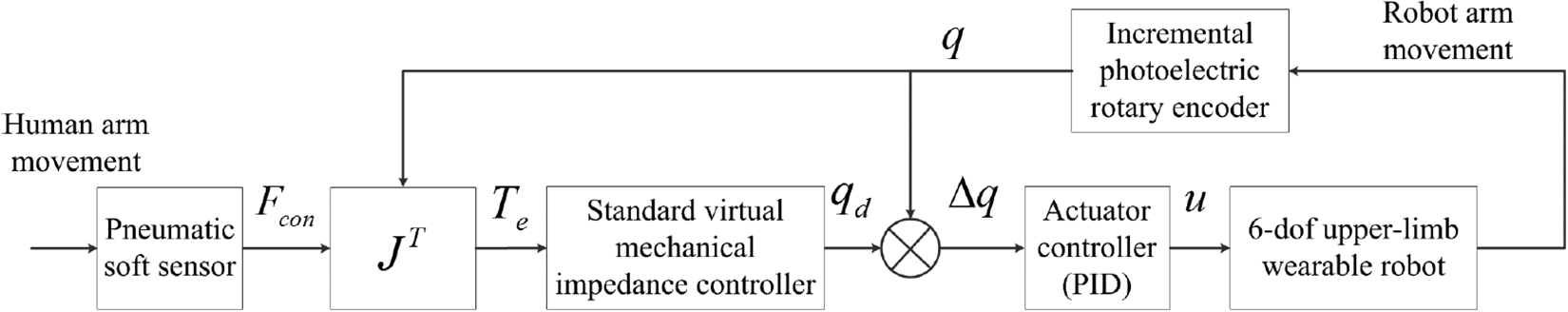
The three-tier hierarchical control structure that was developed for human–robot interaction control is shown in Figure 4. In the new structure, a human arm movement detection (HAMD) module is added to the control structure to guide the robot in lifting tasks. Different gestures can be detected by the HAMD module, which serves as a smart brain, during the whole lifting task. It reduces the asynchrony in movement between the robot arm and human arm. In addition, the Hammerstein adaptive virtual mechanical impedance controller replaces the standard visual mechanical impedance controller in our scheme. The Hammerstein adaptive virtual mechanical impedance model contains nonlinear elements to correct the estimation errors caused by the standard virtual mechanical impedance model. The model is adaptable to human–robot interaction environments during robot-assisted lifting tasks.
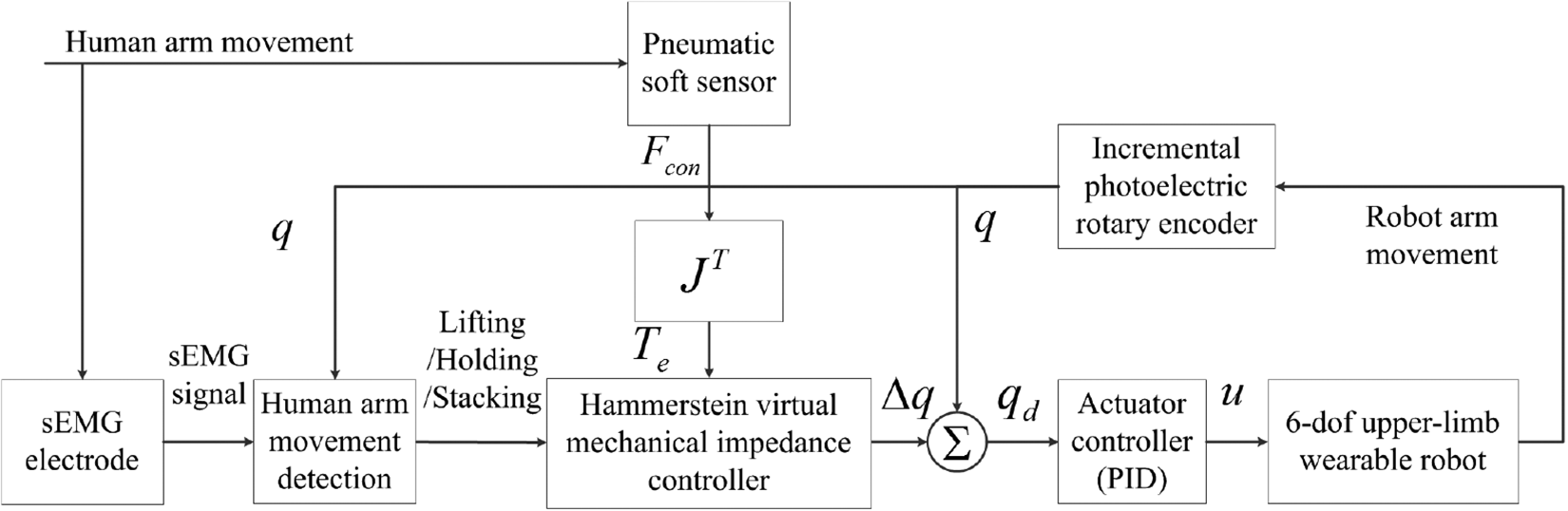
The three-tier hierarchical control structure.
Human arm movement detection
The HAMD module was established using the black box model method, as shown in Figure 5. The module consists of an ANN model, a PCA model, a sliding mean (SM) filter, and a decision marker. Our module is appropriate for building a mathematical relationship among the loading mass, biological signals (sEMG signals), and indexes (BMI and the muscle mass) in different postures of the human arm in robot-assisted lifting tasks. However, the HAMD module is different from the musculoskeletal model. The output of the musculoskeletal model is the estimation value of the human joint angle. The robot follows the joint trajectory to restrict human arm movement. In contrast, the output of our module is the movement phase of the human arm, such as the lifting, holding, and stacking phase. Then, the robot matches the human arm movement (by adjusting air pressures of the PAMs) and provides assistance.

The structure of the HAMD module.
Before the robot-assisted lifting tasks are executed, the ANN model is used to estimate the loading mass in the human arm. The benefit of an ANN in determining complex relationships between the inputs and outputs is that it makes the application of complex model easy. However, the sEMG signal is weak, nonstationary, and random. It is difficult to send the signal directly to the ANN model. Therefore, a bandpass filter with a low cutoff frequency of 20 Hz and a high cutoff frequency of 500 Hz is applied to the raw sEMG signal. Then, we calculate the MAV of the signal in the time domain. The MAV is one of the features that are insensitive to disturbances caused by sEMG electrode location shifts, variation in muscle contraction effort, and muscle fatigue. The MAV can be expressed as
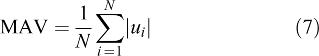
where N is the length of the segment and ui is the processed sEMG signals at i time point.
In our robot system, PCA is a statistical procedure used to develop the human arm joint angle estimation model. The set of observations includes the features of the sEMG signals, loading mass, muscle mass, and BMI. Muscle strength can be estimated from the amplitude of the sEMG signal. It can be described as

where λ is the nonlinear coefficient.
The principal components can be described as

where Y 1 and Y 2 are the principal components; KG is the loading mass; BMI is the body mass index; Mm is the muscle mass; and α, β, γ, ϕ, and δ are the coefficients.
The relationship between the principal components and the estimated human joint angle is shown as

where
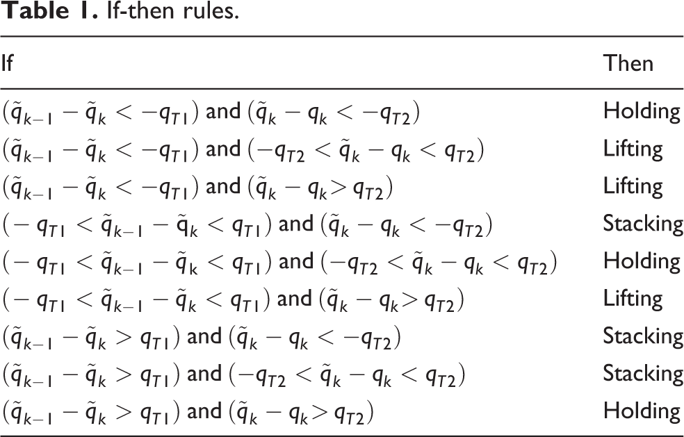
Then, to smooth the angle trajectory, an SM filter is necessary, as shown in Figure 5. A decision marker block, as a classifier, can be used to classify the arm gestures into three phases: lifting, holding, and stacking. The if-then rules are given in Table 1.
If-then rules.
Hammerstein adaptive virtual mechanical impedance controller
As shown in Figure 3, the standard virtual mechanical impedance model was used to build a linear relationship between the actual human–robot interactive torque and the robot joint position for control. The output of the model depends on the accuracy of the dynamic parameters of the physical human–robot interaction model (M, B, and K). The parameters can be tuned using adaptive control or fuzzy control. However, to make a device with more human-like mechanics, a linear relationship is not appropriate to describe the interaction in actual robot-assisted lifting tasks. The Hammerstein virtual mechanical impedance model comprises a static nonlinear model and a time-varying linear model. It can correct the estimation errors caused by the linear model in the robot-assisted lifting environment.
In the Hammerstein virtual mechanical impedance model, Ve is defined as a static nonlinear variable, as shown in formulas (11) and (12)


Formula (12) is a transfer function. Ve
is regarded as the sum of different orders of Te
and
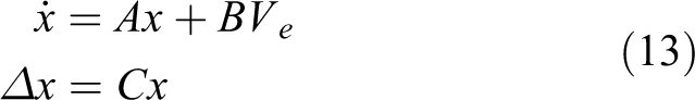
where A, B, and C are polynomial metrics.
While

To designs an adaptive law to adjust the model parameter, a Lyapunov function is defined as

where P and R are symmetric positive definite matrixes.
According to the Lyapunov function, there exist a positive definite matrix Q such that

where
The time derivative of the Lyapunov function is calculated as

If

Finally, the sampling time is taken as Tt
, and the adaptive law

where
Simulation and experiment
In this section, we present the simulation and experiment performed in the study. To test the accuracy of the HAMD module in the laboratory, we designed an experiment for HAMD. Then, a simulation of the interactive torque control was designed to assess the performance of the Hammerstein adaptive virtual mechanical impedance controller in adjusting the interactive torque on the human elbow joint. In addition, a load lifting experiment was conducted to evaluate the upper-limb wearable robot in reducing muscle activity and making interactive torque adjustments during actual lifting tasks.
Experiment for human arm movement detection
From the above sections, the principle of the HAMD module was determined. In this part, we trained and tested the module to detect human arm movement in the laboratory. Since the subjects raised their arms without robot assistance, there was no submodule of if-then rules tested in this experiment.
Six different subjects, as given in Table 2, participated in the experiment. They were asked to catch objects with different loading masses (0, 1, 2, and 3 kg dumbbells) with one arm, as shown in Figure 6. Each subject was asked to keep their arm in full extension (defined as 5° in the elbow joint) for 5 s. Then, all of the subjects were asked to lift objects with one arm. Each subject was asked to maintain an upright position and lift the objects with different masses from the fully extended position to the low position (defined as 30° in the elbow joint), the high position (defined as 60° in the elbow joint), and the horizontal position of the forearm (defined as 90° in the elbow joint). Each movement took 10 s and was performed five times. A 30-s break was provided between each movement. To record the rotation trajectory of the elbow joint, each subject wore two inertial measurement units (MPU6050, Guangyun Electronic Inc., China) on the forearm and upper arm. IMU can record the pitch angle, roll angle, and yaw angle of their own motion. Since the mounting planes of the two IMUs are approximately parallel to the sagittal plane of the subject, the difference in the pitch angles is used to estimate the angle of the human elbow joint. In addition, an electrode (Flex Comp Infiniti, Thought Technology Ltd, Canada) was attached to the long head of the biceps brachii muscle to capture the surface EMG signal.
Subjects information.

BMI: body mass index.

Experimental setup: A male subject stands in an upright position and lifts his forearm without upper arm movement. One electrode is attached to his long head of the biceps brachii muscle, and two IMUs are attached to his upper arm and forearm.
Simulation of the interactive torque control
To further investigate the performance of the Hammerstein adaptive virtual mechanical impedance controller in adjusting the human-robot interactive torque, a simulation was performed in this part.
For the simulation, we built a virtual human–robot environment of the one-arm lifting task using MATLAB 2014a. The loading masses were set to 0, 1, 2, and 3 kg. To simplify the human–robot system, we assumed that only one elbow joint of the upper-limb wearable robot could move. Therefore, the robot arm was regarded as a 1-DOF system. The parameters of the robot were set to be the same as those of the real robot system given in Table 3. In addition, the forearm of the human was regarded as a link, and the length of the link was the same as that of the robot arm. In the simulations, the human moved the elbow joint in a sinusoidal pattern. The joint movement of the trajectory was defined as
The segment parameters of the 6-DOF upper-limb wearable robot.

DOF: degrees of freedom.
Load lifting experiment
Pervious experiment and simulation verified the ability of the three-tier hierarchical control structure to detect human arm motion and to adjust the human–robot interactive torque in laboratory and simulation environments, respectively. To further investigate the advantage of our control structure applied in the upper-limb wearable robot, one manual lifting task and two robot-assisted lifting tasks were designed in this part.
The purpose of the upper-limb wearable robot employing our control structure is to reduce the amount of muscle force required from the user during lifting tasks. Thus, the muscle activity and the heart rate of the user in two modes (with/without robot assistance) were measured and compared during lifting tasks. Therefore, a manual handling experiment was designed for verification. In the manual lifting task, one subject was asked to lift loads with both arms, as shown in Figure 7. A box (length: 50 cm, width: 35 cm, height: 20 cm, mass: 2 kg) and two objects (loading mass: 2 and 4 kg) were used. The box with handles was positioned on an adjustable table, which was set at a height of 72 cm above the ground. One cycle of the task involved lifting the box from the table, holding it, and stacking it at waist height within 10 s. A 30-s break was provided between each cycle so that the subject’s heart rate returned to normal. The subject’s torso was held in an upright position in each cycle. The task was performed for 10 min in each load condition (2, 4, and 6 kg) with a 30-min recovery period. To evaluate the effect of the upper-limb wearable robot on muscle activity, the sEMG signals from the erector spinae and biceps brachii muscles were recorded. Then, we designed a robot-assisted lifting task using the three-tier hierarchical control structure. The subject was asked to lift the box with our upper-limb wearable robot Four bars were used to set the air pressure of the PAMs. The subject performed the same movement as in the manual lifting task. To simplify the robot system without changing the control structure, we assumed that the nondominant hand and the dominant hand required the same strength when the subject lifted the box with both arms. Therefore, only one electrode was used to detect the human arm movement from the biceps brachii muscle on the dominant side. The heart rate was also recorded during the task.
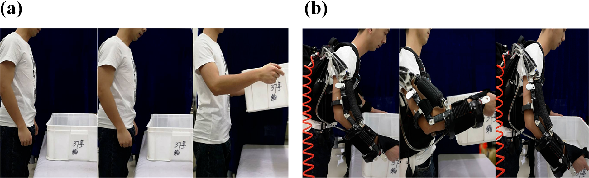
Experimental setup: A subject stood in front of the table and held the box in two states:(a) without the upper-limb wearable robot and (b) with an upper-limb wearable robot.
In addition, our control structure was used to adjust the interactive torque applied to the user’s elbow joint. For this purpose, the human–robot interactive torque was estimated by the pneumatic soft sensor. Therefore, another handling experiment was designed for verification. In this task, the subject with the robot performed the same cyclical movement using the standard virtual mechanical impedance control structure (parameters:
Result
The results of the HAMD task are described in this section. Figure 8 shows different segments of the elbow flexion angles that were obtained using the IMUs (measured value) and our module (calculated value). For all subjects, the module started at 0 s. The deviation (ed ) between the measured value (qM ) and calculated value (qC ) can be calculated by formula (20). The box plot gives statistical information (minimum, median, upper quartile, lower quartile, and maximum) on the distribution of the deviations, as shown in Figure 9. In our experiment, all of the deviations are distributed within [−9.03, 6.91] degrees. At 95% confidence level, the average of deviation is from −0.03° to −1.68°. These results indicate that the EMG signal from the biceps muscle followed the movement of the elbow joint angle and that our model has the ability to detect arm movements


Flexion angles obtained from the measurement (blue line) and calculated by the human arm movement detection module (red line). (a–f) Segments (a) to (f) represent subjects A to F.

The deviation of the experiment for human arm movement detection. (a) Subject A to F and (b) all of the subjects.
The performance of the Hammerstein adaptive virtual mechanical impedance controller is shown in Figure 10(a). The threshold (Td ) is set to be 2 Nm in the simulation. It determines the upper and lower boundary of the controller. Therefore, the human–robot interactive torque varies close to the interval of [−2,2] Nm. Figure 10(b) shows the result of the interactive torque trajectory under the external loads. From the simulations, the maximum torques are 2.07, 2.08, and 2.11 Nm. These results indicate that the Hammerstein adaptive virtual mechanical impedance controller effectively adjusts the interactive torque on the human elbow joint.

The result of the Hammerstein adaptive virtual mechanical impedance controller. The initial values of
For the load-lifting experiment, Figure 11 shows the comparison of the related muscular activations with different lifting tasks. Starting from the sEMG data collection, the EMG signals are normalized and divided into phases for each cycle of the lifting movement. Then, the RMS of the signals is computed per trace. The RMS can be calculated as

where N is the length of the segment and ui is the processed sEMG signal at i time point.
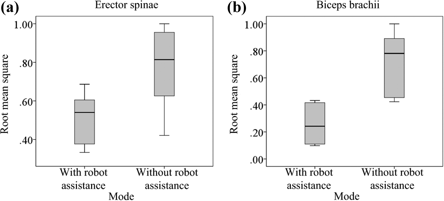
Average muscular activation for all participants with robot assistance (in our scheme) and without robot assistance. (a) At the erector spinae muscle and (b) at the biceps brachii muscle.
As provided in Tables 4 and 5, the average reduction in muscle activity of the erector spinae and biceps brachii muscles decreased by 32.51% and 65.15%, respectively. The statistical significance of the effect of the assistance on each muscle was assessed by repeated-measures analysis of variance (ANOVA) with the mode as an independent factor (with robot assistance in our scheme and without robot assistance) using MATLAB 2014a. The ANOVA results showed a significant difference (both p < 0.001) in muscular effort between the two modes at a 99.9% confidence interval for the difference in the actual lifting task. Therefore, our method can reduce the muscular activation of the user, as we intended.
RMS of the sEMG signal, SD, and muscle activity reduction in erector spinae.

RMS: root mean square; sEMG: surface electromyography; SD: standard deviation.
RMS of the sEMG signal, standard deviation SD, and muscle activity reduction in biceps brachii.

RMS: root mean square; SD: standard deviation; sEMG: surface electromyography.
The human–robot interaction is also illustrated in this section. Figure 12 shows several curves of the human–robot interactive torque in the robot-assisted lifting tasks. All of the curves decrease gradually after overshooting the threshold value. It is practical to make 4 bars available to avoid movement hazards and electronics-related risks caused by high air pressure, although the response speed of the PAMs is limited in the robot-assisted lifting task. According to the test results, the mean amount of overshooting in our control structure is 3.89 ± 0.49 Nm. According to the contrast test results, the mean amount of overshooting of the torque is 8.04 ± 2.31 Nm using the standard virtual mechanical impedance control method. These results illustrate the favorable effect of our control structure in actual lifting work.

Interactive torque curves in different kinds of control structures. (a) Standard virtual mechanical impedance control structure and (b) our control structure.
In our study, the heart rate was compared, as shown in Figure 13. The average heart rate (AHR) without robot assistance (

Results for the heart rate in different modes. (a) Without robot assistance and (b) with robot assistance (in our scheme).
Results for the metabolic rate. Change in metabolic rate = (Average heart rate in robot−assisted lifting task)/(Average heart rate in manual lifting task) − 1.

Discussion
Previous studies have provided some successful examples for human–robot cooperative control of the upper-limb wearable robots. 6 –9 However, these methods have not mentioned how to reduce the overshooting of the interactive torque between the user and the robot. In this article, a control structure has been designed for the upper-limb wearable robots to reduce the amount of overshooting of the interactive torque between the robot and its user in lifting tasks. From the experiments, the mean amount of overshooting of the torque on the elbow joint was 3.89 ± 0.49 Nm, lower than 18.06 15,16 and 50 Nm. 40 It meant that the asynchrony between the human arm and robot arm has been reduced. Meanwhile, different from the standard virtual mechanical impedance controller, 7,8 the Hammerstein adaptive virtual mechanical impedance controller could reduce the overshooting of the interactive torque by adjusting the robot angle without clear dynamic parameters. It should be noted that the interactive torque trajectories on the subject’s elbow joint had small vibrations in the experiments. These vibrations indicate that the arm made a small number of irregular movements and then our robot responds to the movements. As the actuator of the robot, the air flow into and out of the PAM unevenly and intermittently, resulting in the small range vibrations. However, this phenomenon is the inherent defect of the PAM. Similar phenomenon was also observed in other study. 41 These small vibrations do not affect the stability of the device during the lifting tasks.
Another benefit of our scheme was to reduce muscular activation in the two muscles during the robot-assisted lifting tasks. In this study, muscular activations of erector spinae and biceps brachii muscles decreased obviously (both p < 0.001). From the experiment, the muscle activity of erector spinae was reduced by 32.51%, and the muscle activity of biceps brachii was reduced by 65.15%. These values were consistent with those in other studies (24–40% in erector spinae 42,43 and 50–70% in biceps brachii 6,43 ). The assistive torque was generated from PAMs and transferred to the human by the mechanical structure and hook-and-loop fasteners to assist elbow joint flexion during the lifting and holding phases. It restrained the muscular activation of the biceps brachii muscle. Then, the interface on the back was designed as a spinal orthotic to prevent spinal injuries; this design has been widely used in robotic exoskeletons and has been shown to reduce the muscular activation of the erector spinae muscle. 2,44
In addition, our scheme changed the physiological state of the user, according to the results. The heart rate was measured to evaluate metabolic cost during the lifting tasks. Generally, metabolic cost has been estimated by hemoglobin levels in the blood and by heart rate in previous studies. 5,38,39 However, these methods were used in aerobic exercises with strict standards. Apparently, these methods are not suitable for the lifting of an object at one time unless the experiment is repeated for a long time to create a change in the wearer’s oxygen consumption. 2,29 Moreover, 2, 4, and 6 kg loads rather than 10 or 15 kg loads were used to allow repeated lifting actions. According to the results, the average metabolic cost increased by 2.51%. However, this increase is a result of the robot lacking a lower-limb structure to unload the force of gravity to the ground. At present, the 6-DOF upper-limb wearable robot is a prototype device with a mass of 5.6 kg. In the robot-assisted lifting mode, even when the subject lifts an object with the same loading mass as that lifted in the manual lifting mode, the gravitational force from the robot is applied to the subject’s upper limb, which is equivalent to the force from carrying a heavier object than that lifted in the manual lifting mode. Therefore, the AHR of the subject increases. It should be noted that our study focuses on a control structure for reducing the amount of overshoot in the human–robot interactive torque of an upper-limb wearable robot. Reducing metabolic cost to an acceptable rate will be studied in our future work.
Conclusion
To conclude, a three-tier hierarchical control structure was developed for an upper-limb wearable robot to reduce muscle activity while preventing mechanical injuries in actual lifting tasks. To detect the user’s arm movement and generate an acceptable interactive torque on the human elbow joint, a HAMD module that used sEMG signals and a Hammerstein adaptive virtual mechanical impedance controller was proposed in this article. Then, several experiments were designed to illustrate the effect of our scheme in application. According to the results, our scheme could reduce the amount of overshooting of the interactive torque and provide assistance to the user’s arm, while the erector spinae and biceps brachii muscular activations could be significantly reduced.
Footnotes
Declaration of conflicting interests
The author(s) declared no potential conflicts of interest with respect to the research, authorship, and/or publication of this article.
Funding
The author(s) disclosed receipt of the following financial support for the research, authorship, and/or publication of this article: This work was supported by the National Natural Science Foundation of China [Grant No. 61873054] and Fundamental Research Funds for the Central Universities [Grant Nos: N170804006 and N18240007-2].