
Abstract
In complex traffic scenarios, more accurate measurement and discrimination for an automotive frequency-modulated continuous-wave (FMCW) radar is required for intelligent robots, driverless cars and driver-assistant systems. A more accurate range estimation method based on a local resampling Fourier transform (LRFT) for a FMCW radar is developed in this paper. Radar signal correlation in the phase space sees a higher signal-noise-ratio (SNR) to achieve more accurate ranging, and the LRFT - which acts on a local neighbour as a refinement step - can achieve a more accurate target range. The rough range is estimated through conditional pulse compression (PC) and then, around the initial rough estimation, a refined estimation through the LRFT in the local region achieves greater precision. Furthermore, the LRFT algorithm is tested in numerous simulations and physical system experiments, which show that the LRFT algorithm achieves a more precise range estimation than traditional FFT-based algorithms, especially for lower bandwidth signals.
1. Introduction
Automotive millimetre-wave (MMW) frequency-modulated continuous-wave (FMCW) radars are generally used in diverse applications owing to their low cost, simplicity and robustness in foggy, rainy, dusty and humid conditions [1, 2], and they are often configured as medium-range and long-range radars for intelligent robots, driverless cars and driver-assistant systems [3]. These radars have also been used in ground and maritime surveillance tasks for the detection and tracking of targets [4, 5].
High-performance automotive radar systems have been available on the market at 77 GHz; furthermore, an accurate and high-resolution target range and velocity can be measured simultaneously, even in multi-target situations. It is a specific task for a radar to measure a single object's range and radial velocity simultaneously within a single measurement cycle. A single pulse is transmitted and received to measure the range. A continuous wave (or pulse-Doppler) radar is used to measure the radial velocity. In order to measure the range and radial velocity simultaneously within a single measurement cycle, waveforms such as FMCW, mono-pulse, multiple frequency shift keying (MFSK), frequency shift keying (FSK) and chirp sequence (CS) [6] are usually adopted in automotive radar.
A typical approach to measure the range and velocity is to analyse the Fourier spectrum of the received beat signal in FMCW radar. The convolution of the received signal and the transmitted signals is usually used to reach the Fourier spectrum. However, precise range measurement is possible when caused by signal delay, which is determined by the number of samples, the ADC sampling rate, the signal bandwidth and the chirp period, while at the same time the Doppler frequency estimation's precision determines the velocity measure's accuracy [7]. As such, the estimated accuracy of the range and velocity is limited.
The frequency of the beat-note signal is the basis of the range estimation for FMCW-level radar. The instantaneous phase of the sampled series is calculated and is then used to estimate the frequency of a single-tone – however, phase unwrapping is needed to eliminate any ambiguity [8]. To achieve good performance for the ranging in a low Signal Noise Ratio (SNR) situation, frequency estimation techniques employ the correlation algorithm between the sampled data. Frequency estimation algorithms based on the phase difference or the instantaneous phase have to achieve a trade-off between the efficiency of the frequency estimation and its accuracy. In addition, the frequency can be estimated by other methods. In [9, 10], a spectral estimation algorithm based on frequency interpolation for range and velocity enhancement was employed, but the frequency interpolation is based on a nonlinear regression, which is sensitive to the selection of the regression function. FFT is a traditional method for estimating the frequency of signals; however, the duration of the observation limits the estimation accuracy, which is considered to be its obvious drawback. The frequency estimation accuracy can be improved by zero-padded FFT [11], but this will increase the computational burden and demand on memory. Variable sweep time [12] or data oversampling strategies [13] were also used to increase the resolution or sampling precision, which will improve the frequency estimation's precision.
In this paper, we develop an LRFT method for fast and accurate range estimation for an automotive FMCW radar. The method uses the phase correlation technique to achieve a higher SNR pulse compression (PC) spectrum, and then a virtual sample transform is used in a local neighbour around the initial rough estimation to achieve accurate, efficient and robust range parameters. This is a newly developed method of PC using transmitted signals and received signals. The phase correlation-based PC spectrum is used to estimate a rough estimation in order to construct a virtual sample matrix. Then a small region around the rough estimation is transformed by the inverse Fourier transform with a matrix form to achieve a refined delta function. Therefore, wse can estimate spectrum peak location and the target's range more precisely. The method works efficiently because of the transformation in the frequency domain by working on a small local neighbourhood and operating as a fast inverse Fourier transform.
The contents of this paper are as follows: in Section 2, we give the FMCW radar's basic range estimation principle. In Section 3, we describe the LRFT method and the developed range estimation algorithm. In Section 4, experimental results are then shown on a simulative platform and a physical system. Finally, a conclusion is given in Section 5.
2. Overview of the FMCW radar and range measuring
A 24 GHz automotive radar is used to measure pedestrians for the evaluation of the proposed algorithm in Section 3. For high-accuracy measurements, the voltage-controlled oscillator (VCO) of the radar must be stabilized with a phase-locked loop (PLL). To minimize the influence of multiple reflections, a parasitic patch antenna in combination with a lens is used as the radar antenna. The radar antenna has an overall gain of 20 dBm and an antenna horizontal beam-width of 23° [14]. As the reference system, the inductive measurement system IVQ-905 K-band VCO antenna by InnoSent Corp. of Germany, which achieves a maximum accuracy of 1 µm, is used. After the A/D conversion of the beat-frequency signal, the samples are sent to a TMS320F28335 processing unit for online signal processing. To reduce the computing time and minimize the influence of distortion, the beat frequency at each measurement position is calculated by a de-chirp algorithm and the Hamming window.

A 24 GHz automotive radar configuration
The range and velocity of a target is estimated by the FMCW radar transmitting a frequency-modulated continuous wave. To a stationary target, frequencies can be described through td, the time of the transmitted signal and received signals, as shown in Fig. 2 [15, 16], where fc is the centre frequency, B is the modulation bandwidth of the signal, and f0 is the starting frequency. One half of the pulse repetition interval (PRI - also called the chirp period) is described by T.

Frequencies of the transmitted, received and beat signals for a moving target
There will be a Doppler shift in a received signal if it is a moving target, which will be added to the frequency shift caused by td. The difference between the transmitted signal and the received signal is the beat frequency; furthermore, the up-chirp and down-chirp beat-frequencies are denoted, respectively, as
Therefore, fr and fd are usually obtained through a signal processing process, and then we can estimate the radial distance and velocity of the target using Equations (1) and (2),


where C is the speed of light, B is the modulation bandwidth and T denotes the PRI, which is the chirp period.
The difference between the ideal beat-frequency in the continuous frequency domain and that in the discrete frequency domain in Equation (3) is called the “measure error” of the beat frequency [17]. Here, the ideal beat-frequency is denoted by

Therefore, the steps for the range and velocity are shown in Equations (4) and (5), respectively. At the same time, the maximum error of the range and velocity are equal to
The range step


Here,

In this equation,
3. Accurate range estimation based on the LRFT
In our work, we apply a refinement step to enhance the range estimation after the de-chirp process in the FMCW radar for target detection and range measuring.
Both signals are embedded in a phase space by creating delay vectors. The signal

The inverse Fourier transform of
In fact, the local virtual sampling Fourier transform is not an additional approximation technique - it simply discards information outside the valid region, for example, the side-lobe information, and the result is an efficient inverse Fourier transform without any iteration [21]. We will present the algorithm of the local virtual sampling Fourier transform together with its theory in detail in what follows.
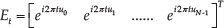
We define the matrix-form Fourier transform of the N -dimensional signal

where
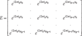
Equation (8) is deduced from the Riemann sum of the continuous Fourier transform, which is also called the matrix-form Fourier transform (MFFT); however, if N B is equal to N, Equation (8) will be the Discrete Fourier Transform (DFT) of the signal. We define the local virtual frequency sampling in the following according to the definition of the MFFT.
As is well known, a discrete signal in the Fourier domain corresponds to a continuous periodic signal in the spatial domain; therefore, a new sampling strategy is presented to obtain a signal with a higher resolution in the spatial domain, which is a higher sample rate and which is used when we transform the signal from the frequency to the spatial domain.
Given the virtual sampled region size m (usually

where
The construction of the base function is the most important part of the local virtual sample in the PC spectrum, as shown in Equation (9). The virtual sample region is set on the basis of m after tM is estimated. To construct the sample vector T in the spatial domain, we resample R with a
As such, we define the local virtual sample of the PC spectrum Phs(u) on R as

where
The conventional DFT requires that NC (
To estimate the target range, the PC spectrum of s(t) - which is the echo signal of the radar - and the impulse response h(t) of the matched filter is constructed according to Equation (2). Next, a Dirac delta function is achieved by the inverse Fourier transformation of the PC spectrum, whose peak location is denoted by d0, such that d0 is considered to be the initial rough estimate of the range through the traditional FFT-based signal correlation algorithm. Furthermore, the PC spectrum is resampled virtually in a small region around d0, and then we achieve high accuracy in the local PC spectrum


where d is the estimated target range detected by the radar. This method is the LRFT for the target range estimation.
Fig. 3(a) shows a receive-window PC spectrum achieved by the conventional FFT method. The peak location of the spectrum, which is shown in Fig. 3(b) in detail, corresponds to the rough range estimation. A more accurate range estimation cannot be achieved by this method. The virtual sample PC spectrum is described by the red line in Fig. 3(b), and the black line is part of the traditional FFT-based PC spectrum around its peak. From the comparison, it can be concluded that the LRFT spectrum's peak location is more accurate.
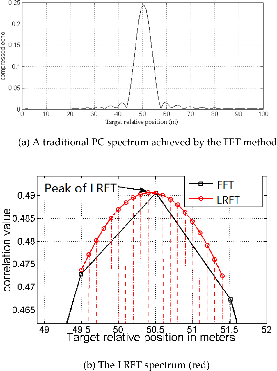
Spectrum of PC and the LRFT (m=2, k=10)
4. Experimental results and discussion
In this section, we present the experimental validation of the algorithm's performance on synthesis data and a physical system, and the efficiency analysis of the LRFT for radar range estimation is also introduced.
4.1. Experiments on synthesis data
Firstly, the precision experiments for the LRFT algorithm are introduced. Next, our method is compared with traditional FFT-based PC. Finally, we introduce the computational time of the LRFT. We validate the LRFT method in MATLAB 2009b, running on a Pentium IV 2.8 GHz Intel CPU with 1,024 Mb memory.
The range estimation precision of the LRFT is validated at different bandwidths, and the parameters of the simulated radar are as follows: the receive-window size is 500 m, the scatters RCS is 1 m2, and the bandwidth changes from 10 MHz to 100 MHz. The resample step k in the LRFT is set to 10. We test the range estimate precision at each bandwidth setting for scatter ranges from 10 m to 750 m with 25 m steps, and we then average the range estimate error corresponding to the bandwidth. Table 1 shows the experimental results.
Averaged estimation error of the LRFT corresponding to different bandwidths

It can be seen in Table 1 that even if the bandwidth is narrow - such as 10 MHz - the range is still estimated accurately.
Next, we compare the precision of our LRFT method and the traditional FFT-based PC method. At a given bandwidth, we simulate 10 random scatters and estimate the corresponding 10 range errors separately, and finally the 10 errors are averaged. Figure 4 shows the comparison of the experimental results, and it is found that the range-estimate errors of the LRFT decrease sharply at bandwidths lower than 70 MHz compared with the FFT-based PC method. The parameter p shown in Figure 5, which characterizes the improvement in precision of our method, is defined in Equation (15),

where
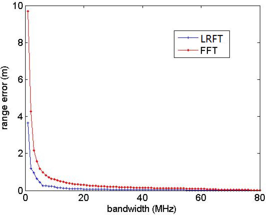
Range estimation comparison between the FFT-based method and our LRFT method

The range estimation precision improvement of the LRFT compared with the traditional FFT method
At the same time, the robustness of the LRFT is validated, Gaussian white noise is added to the echo signals. For every bandwidth, 50 times Monte Carlo experiments are designed with random noise of SNR from −20 dB to −5d B tested then the range estimation errors are averaged. The results are shown in Table 2, from which it can be seen that the LRFT method achieves greater accuracy than the conventional FFT-based method when disturbed by Gaussian white noise, and from the improvement in precision p it can be seen that the accuracy is improved by more than 35% at the lower bandwidth.
Range estimation errors of the LRFT and the FFT-based method

The experiments show that we achieve a more precise range estimation using the LRFT method, especially when the radar works at lower bandwidths, and we can get more than 60% improvement in precision (lower than 80 MHz) compared with the traditional FFT-based PC method. Furthermore, the statistical average time for each range estimation is about 0.6 ms and 0.7 ms for the FFT-based method and the LRFT, respectively, which concurs with the analysis in [21] such that, compared with most FFT-based methods, the local virtual sample technique does not significantly increase the computational burden.
4.2. Experiments on a physical system
Our algorithm was tested on the physical radar system described in Section 2 to validate the performance for accurate range estimation. The parameters of our radar are shown in Table 3 in detail.
The detailed parameters of our 24 GHz IVQ-905 radar

We conducted an experiment in a field test for a pedestrian detection and positioning scenario to obtain accurate measurement results and assess our algorithm's ranging precision.
In this experiment, the radar has a central frequency

MMW radar target measurement scenario in the field test
To demonstrate the functionality of the algorithm, a quantitative evaluation is performed to analyse the precision for the ranging, and we compare the LRFT algorithm for range enhancement, such that there is about a 30% improvement overall.
5. Conclusion
Automotive MMW radars offer - in general - the capability to measure extremely accurately the target range, radial velocity and azimuth angle for all objects inside the observation area of intelligent vehicles or mobile robots. In this paper, a novel LRFT method for automotive MMW radar range estimation is developed. The LRFT is a method based on a local virtual sample of the PC spectrum in a phase space, which uses a matrix local resample Fourier Transform to achieve virtual resampling in a local neighbourhood of the PC spectrum and estimate the range accurately. From the synthesis data experiments, it was found that we can achieve more accurate estimations compared with the traditional FFT-based method, especially at lower bandwidths. Furthermore, physical radar system experiments have shown the application of our method to pedestrian detection and positioning.
Footnotes
6. Acknowledgements
This work was partially supported by a fund from the National 863 High Technology Research Fund (2015AA8106043), the National Science Foundation of China (Grant No.61402237, 61302156), the Foundation of Nanjing University of Posts and Telecommunication (Grant No. NY212026, and NY213168), and the Jiangsu Key Laboratory of Image and Video Understanding for Social Safety (Nanjing University of Science and Technology - Grant No. 30920140122007).