
Abstract
To improve the mobility of the quadruped robot, a planar hopping control approach is proposed based on trotting gait. With the proposed approach, three joints of the stance legs are active and the fourth leg is passive. A planar kinematic model of the supporting phase is built and the calculated positions and posture of the torso are used as feedback for motion control. The forces and torque acting at the CoM of the robot torso in the plane are fully controllable and decoupled with the control approach based on a virtual model. The planar motions on three axes are controlled independently. For the hopping control, the total energy in a hopping cycle on the vertical direction is planned according to the desired hopping height of the torso's CoM and the virtual vertical stiffness of the torso is generated using the elastic potential energy of the virtual model. We verify the approach and its robustness using simulation experiments and show the results at the end of this paper.
1. Introduction
Following billions of years of evolution, almost all terrestrial animals are legged and can go anywhere on land using these legs. Compared to wheeled and tracked mobile platforms, more agile and versatile four-legged platforms have incomparable superiority in terms of locomotion on complex terrain [1]. On the other hand, four-legged platforms have fewer joints than six-legged ones and are therefore more stable than single-legged and biped ones. Hence, a four-legged robot is a better option for meeting the demands of fast locomotion and transportation on rough terrains such as those presented by forests and mountains [2].
In the past few decades, there has been a developing boom in the area of quadruped robots. BigDog, as one of the most advanced quadruped robots in the world, can traverse a range of complex terrains and represents a milestone in the development of quadruped robots [3]. In addition to BigDog, LS3 was introduced by Boston Dynamics (BDI) as a prototype of a legged supporting vehicle [4]. HyQ from the Italian Institute of Technology (IIT) is another famous quadruped robot platform, but still being developed in the lab [5]. Additionally, JINPOONG from the Korea Institute of Industrial Technology (KITECH) [7] and SCalf from Shandong University (SDU) [8] are also worth noting in the field of quadruped robot research. These platforms are all hydraulic and are the same size as BigDog. Many different approaches to balancing and locomotion control have also been developed to enable these platforms to walk and run on rough terrain via dynamic gait.
In order to further improve the mobility of quadruped robots, some control approaches to genuine running gait have been developed and realized. The duty factor in the supporting phase β [9] of such gaits is less than 0.5. There is no doubt that the three-part control method based on the spring loaded inverted pendulum (SLIP) model presented by Raibert has been successful in terms of balancing and the dynamic locomotion control of legged robots [10]. Such a quadruped running robot achieved a world land speed record for legged robots (6 m/s) in the 1980s [3]. Ahmadi and Buehler presented a stable running control approach based on a one-legged model with hip and leg compliance [11]. Sato and Buehler realized planar hopping control on a one-legged robot with only one actuator [12]. Smith and Poulakakis realized a rotary gallop on SCOUT II [13]. MIT's Cheetah, developed in a biomimetic robotics laboratory (BRL), can gallop at a speed up to 22 km/h in the lab with its compliant mechanism [14,15] and optimally scaled hip-force planning (OSHP) [16]. Shkolnik, Levashov, Manchester and Tedrake presented their bounding approach on rough terrain based on a planar model and the rapidly exploring random tree (RRT) [17]. The BDI cheetah is currently the fastest quadruped robot with a 17.6m/s galloping gait and its improved type, WildCat, can gallop and bound outdoors using its onboard power system [18].
However, neither running-based or one-legged models such as SLIP, or any other approach using a planar model can render all degrees of freedom (DoFs) for the torso controllable.
To solve this problem, a decoupled motion control approach is proposed based on a planar model of supporting phase with trotting gait [1] and virtual model control [19,20]. There is one fore stance leg and one rear stance leg at least in the supporting phase of gait.
By planning the total energy with the desired hopping height and the virtual elastic potential energy of the supporting phase on vertical direction, the virtual stiffness of the supporting phase is generated and applied to the torso's centre of mass (CoM) by active impedance control. Using this approach, it will be easier to control a system integrated with high stiffness active joints and passive energy storage units such as the series elastic actuator (SEA) [21].
In the simplified model, one of four joints on the stance legs of the planar robot is passive during the supporting phase. The planar robot loses redundancy and internal force cannot be set. However, with the control approach, only a small amount of torque is needed on a particular active joint in a real robot system. If the main actuator of this joint malfunctions, the robot can keep moving by using a smaller standby actuator.
This paper is organized as follows: section 2 introduces a simplified planar model and provides the kinematics of the model. Section 3 provides a position and proposed control method for the torso's CoM, based on the presented model. Section 4 presents an energy planning-based hopping control approach and section 5 reports the experimental results obtained from simulations. Finally, section 6 presents conclusions and suggestions for further research.
2. Planar Model for Supporting Phase
When a quadruped robot is running steadily with a trotting gait, the planar model of the supporting phase can be simplified as a planar five-bar linkage as shown in Figure 1, as well as two point-feet contact to the ground. If the mass of the torso is significantly greater than the mass of the legs, the CoM of the robot will be approximately the CoM of the torso. The positions and pose of the CoM are described by (

The simplified planar model of the supporting phase, based on trotting gait
The degree of freedom (DoF) of the planar five-linkage is 3 and to enhance the vertical supporting forces and reduce static frictions between the feet and the ground, q1, q2 and q4 are chosen as the active joints. For forward kinematics, the 3-DoF pose of the torso is the function of q1, q2 and q4.
The solution of the kinematic model is divided into two steps as shown in Figure 2.

The two steps for modeling flow
A basic vector equation can be obtained from step 1 as shown in Figure 2 as follows

Let
Unlike the three other vector angles,
Thus, using the geometric method, the forward solution of position in step 1 can be calculated as:

where

where
In step 2, the variables can be substituted as

where
The forward kinematics of the planar model can be obtained by Eq. (2)–(4).
The calculating flow of the forward kinematics is shown in Figure 3.

Calculating flow diagram of the kinematic model
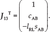
The speed form of the model is also solved by the two steps shown below:
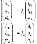
Compared to deriving the forward kinematic equations, solving the speed form of the vector equation is easier than obtaining the angular velocity of CoM. The speed form of Eq. (1) in coordinate frame A, which is fixed to link AB, can be written as:
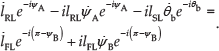
By solving Eq. (6), the pitch angle speed can be obtained as:

under the condition of

where
The linear speed of the CoM can be obtained by substituting Eq. (7) into the derivative of Eq. (2), as shown in Eq. (8)

where,


where

3. Motion Control Based on Virtual Model
A gait cycle is determined by motion during the supporting phase. In this section, a motion control approach is introduced to implement the compliant motion of the torso on three axes, based on virtual model control and the solutions noted in section 2.
3.1. The virtual model control based on the planar model
In the planar motion control,
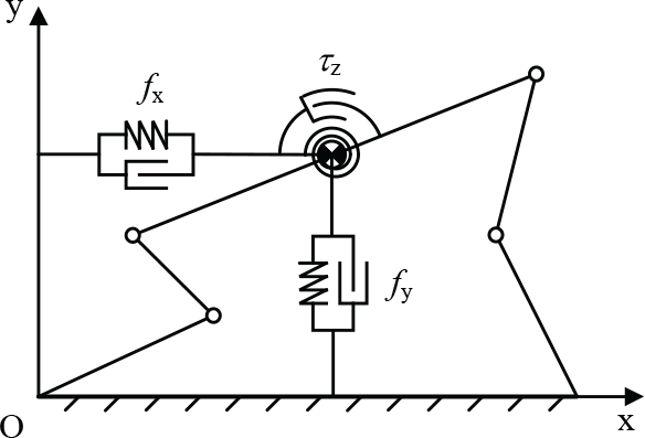
The planar 3-DoF virtual stiffness-damping model
The control law of the virtual model is shown as:

where
Of course, the control forces
However, the robot feet are not actually fixed on the ground; here we render
where the parameters
It is noted that the mass of torso is far greater than the mass of the legs discussed in section 2. Therefore, the following assumption is made:
According to the above assumption, the transformation function from control force space to actuating force space should be the Jacobin matrix as shown below:

where
3.2. Position control based on the virtual model
According to the description above, a virtual model based on a force control block diagram is given in Figure 5.

The block diagram for the motion control
Because the robot feet only just make contact with the ground, the feet may take off. When a foot takes off, the virtual model would get unavailable and cause the locomotion and hopping control to fail. In Figure 6, when ZMP (zero moment point) of the robot is at ZMP1, there is a large margin for adjusting the pitch angle and horizontal acceleration of the robot torso by
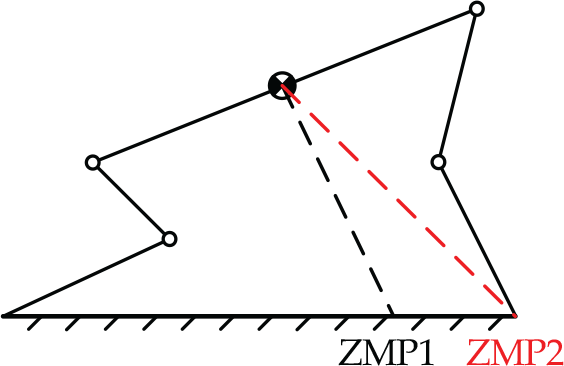
Stability analysis for planar motion
Slip is another problem that may cause the control approach to fail. However, slip is related to the normal supporting force and friction factors between the feet and the ground. This is a rather complex problem for a legged robot, the details of which are beyond the scope of this paper. In the simulation, the friction coefficient between the feet and the ground does not change and is set to 1.
4. Hopping Control with Energy Planning
4.1. Hopping process analysis
For hopping control, a cycle is divided into two phases, referred to as the supporting phase and swing phase, shown in Figure 7. The definitions for symbols are shown in Table 1. The supporting phase lasts from both feet touching down onto the ground to one of the feet leaving the ground. Swing phase is the time between the end of the previous supporting phase and the next.
Symbol definition of the hopping process

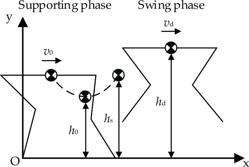
Analysis of the hopping process
Hopping control should only be effected during the supporting phase. The hopping cycle is controlled by variable stiffness along the y -axis of the coordinate frame O based on energy planning of the virtual model. The supporting phase is divided into two periods, i.e., the compressing period and releasing period. The compressing period lasts from the beginning of the supporting phase to the time where the CoM of the robot reaches the lowest position on the y -axis. During this period, the virtual spring on the y -axis stores energy that is also virtual. The energy of hopping motion is charged by changing the vertical virtual stiffness. The releasing period lasts from the end of the compressing period to the end of the supporting phase. During this period, the virtual spring releases the energy and transfers it to kinetic and gravitational potential energy.
Since the controlling virtual forces are decoupled, the kinetic energies and rotational kinetic energy along the x, y and z axes can be controlled separately. This is the primary difference from the SLIP model. The horizontal hopping speed is controlled by
4.2. Hopping height and cycle control
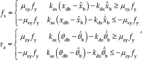
During the supporting phase, the control law of

where,

During the compression period, the desired total energy consists of the virtual elastic potential energy and the gravitational potential energy at the desired minimum CoM height point as follows:
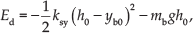
where,
Thus, the virtual stiffness

When
where
During the release period, the desired total energy

The equation for virtual stiffness

Similar to stiffness planning in the compression period, when

The entire hopping cycle control block diagram is illustrated in Figure 8.

Block diagram of the hopping cycle control
4.3. Horizontal velocity control
The horizontal velocity of the torso is controlled by

where
In this paper, the desired pitch angle is zero. The control law of
4.4. Swing foot trajectory planning
The swing time of the swing phase

With trotting gait, the swing time of a foot equals double
However, we cannot certainly know when the foot touches down on the ground, especially on rough terrain. However, the rising time of the swing phase is certain once a foot of robot leaves the ground and this takes half the time of
The trajectory of the swinging feet in the coordinate frame fixed at the CoM of the torso is planned using a cubic curve to avoid the mutation of acceleration, as shown in Eq. (21)

where a0, a1, a2 and a3 are the parameters of the swing trajectory and they can be calculated using the measured feet positions, velocities at the very beginning of swing, and the final desired feet positions and velocities.
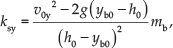
For trajectory planning, we let the step length be adjusted by the horizon velocity of the torso at the time of taking off, which can be shown as follows:

where
A low gain PD control is used as the swing foot position control. Based on the assumption in section 3.1, the gain of the PD control can be very low. Shock will not spread to the torso, even is there is unexpected impact between the foot and the ground.
4.5. Control flow of the hopping cycle
The entire hopping cycle control flow diagram is shown in Figure 9 and is unidirectional. Once moving to the next phase or period, it never falls back to the former phase or period. It is therefore unnecessary to worry about oscillation between two neighboring statuses.
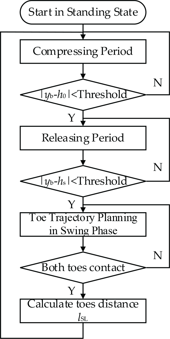
Control flow diagram of a hopping cycle
In the control flow, a hopping cycle is divided into a compressing period and a releasing period in the supporting phase and swing phase. Whether the flow is in the supporting phase or in the swing phase is determined by the touch sensing on each foot. Once the flow moves into the supporting phase,
During the supporting phase,
5. Simulation and Results
To verify the performance of the proposed motion control and hopping control approach, we built a virtual testing system based on Webots 6.4.1, as shown in Figure 10. The motion of the robot is constrained in a plane by two linear motion guides. The torso length (

The virtual testing system and simulation environment
The planar motion and hop of the five-linkage system is demonstrated in the simulation. We conducted two groups of simulated experiments to verify the effectiveness of the proposed locomotion control and the hopping control approach.
5.1. Simulated results in motion control
To verify the presented kinematic model, we let the robot stand on the ground in the simulated environment and the CoM of the robot torso track the desired sine curves on the x, y and z axes, with the force control approach as stated in section 3.1. The parameters in Eq. (11) are estimated by the desired position and single rigid body dynamics of the torso first and then adjusted during the tests.
As the simulation result shows, the position along the x and y axes, and the angular position on the z -axis are shown in Figure 11. The blue curves are the desired values and the red curves are measured by the linear motion guides as the real value of the torso pose. The parameters used here are shown in Table 2.
The parameters used in motion control


Position and pitch angular curves of the torso's CoM under locomotion control along the x, y and z axes in the coordinate frame O with both feet contacting to the ground
With a group of high impedance parameters, the desired and measured curves are shown to almost overlap. Motion control is also verified by this simulation experiment. However, the motion in the experiment lacks compliance due to the use of such high impedance parameters.
5.2. Simulated results for hopping control
In the hopping experiment, the virtual control forces
The experiments were conducted with a horizontal robot velocity (
The parameters used in hopping control with a horizontal velocity of 2 m/s

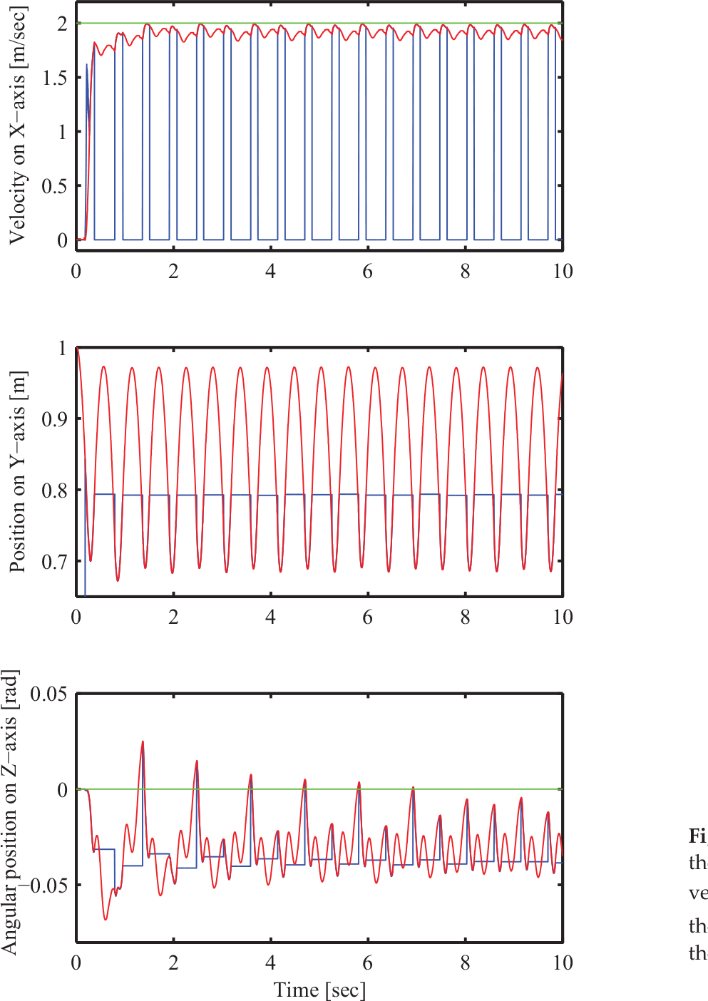
The CoM velocity and position curves of the robot torso on three axes are shown in Figure 12. The red and blue curves are the real values measured by the linear guides and the feedback values calculated by the forward kinematic model. The calculated values are only available during the supporting phase; we stopped refreshing the calculated values and set them to the initial values during the swing phase, so that the blue curves are discontinuous.

Velocity and position curves of the robot torso's CoM with the hopping control, velocity along the x -axis, position along the y -axis and angular position along the z -axis in the coordinate frame O, as shown in Figure 10. The curves drawn in red are the values measured by the two guides, the blue curves are calculated by the forward kinematics and the green curves are the desired values.
According to the velocity curves on the x -axis, the speed is up to the desired input (2 m/s) at the ninth hopping cycle. Due to the high values of
The evolution of the vertical stiffness of the virtual model is shown in Figure 13. The speed becomes higher, the energy loss caused by the shock from the feet also becomes higher and more energy is needed to support the buffering period. Thus, stiffness during buffering period is bigger than during the releasing period. When

The evolution of the vertical stiffness of the virtual model during hopping with horizontal velocity at 2 m/s
The torques of the four joints are shown in Figure 14. During the swing phase, the joint torque outputs are all very low to keep the feet positions steady. The feet are compliant enough to touch but not crush onto the ground. Discontinuity of the curves is caused by changes in the stiffness between the compressing period and releasing period in the supporting phase.

The torques on the four joints; joint 3 is passive during the supporting phase and active during the swing phase
5.3. Robustness study with different leg masses
The previous simulations are based on the assumption of the control approach presented in section 3.1 and with a very low mass ratio of leg/torso (1:500). But what will happen if this assumption is not satisfied? To test the performance of the control approach in this paper with different leg link masses, we conducted two experiments using different mass ratios (1:50 and 1:5).
When each leg link mass is 0.05kg and the torso mass is 5kg, the parameters are the same as in the simulation with a leg link mass of 0.005kg, for except
With a leg link mass of 0.05kg, the velocity and position curves of the robot torso's CoM is shown during the hop. The desired horizontal velocity (
When the leg link mass is raised to 0.5kg, the mass ratio of leg/torso is raised to 1:5 and the rotation of the torso pitch angle cased by the swing leg cannot be ignored any longer in the swing phase. We have to set the desired torso's pitch angle at 0.15 rad to compensate for the rotation of the torso in the swing phase and the control parameters for doing so are shown in Table 4. The vibration of the torso's pitch angle is very strong, but there is no change in the control approach. The results of the experiment with a leg mass of 0.5kg are shown in Figure 16. The vibration of the torso pitch becomes much more severe than in previous experiments. Another simulation of 40 seconds shows that the hop merges into a cyclic motion and the robot runs steadily.
The parameters used in hopping control with a leg link mass of 0.5kg and a desired horizontal velocity (
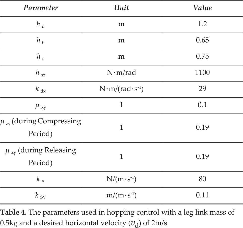

With a leg link mass of 0.5kg, the velocity and position curves of the robot torso's CoM is shown during hopping. The desired horizontal velocity (
A demo of the experimental results can be viewed at the following URL: http://v.youku.com/v_show/id_XMTM1NTA2MTAyMA==.html.
6. Conclusions and Discussions
In this paper, we presented a planar hopping control approach using a virtual model and energy planning based on trotting gait. Using this approach, the planar motions of the robot's torso are decoupled and fully controllable in the supporting phase. The proposed hopping control approach is verified by simulated experiments. A number of conclusions are drawn as follows.
Firstly, this approach is easy to implement using a micro controller since computation complexity is very low. In the hopping control, stiffness on the y -axis is generated by the energy of the virtual model; this calculation highly depends on kinematics and velocities and as such the calculation is simpler than using a dynamics model, and the controller does not require high computing capabilities for real-time control.
Secondly, gait is generated by the planned energy and contact status of the feet, and is more adaptable to the environment than gait planning based on time. A single leg remains in the swing phase when the foot touches the ground, except in the case of low stiffness or driving force. Motion control of the foot with low stiffness in the swing phase can effectively reduce impact when unexpected contact occurs between the foot and ground. When the gait is switched from the swing phase to the supporting phase, both feet of the robot touch on the ground, and the virtual vertical stiffness takes effect. When the gait is switched from the supporting phase to the swing phase, one foot takes off from the ground, the virtual vertical stiffness gets unavailable. Therefore, gait can be aperiodic.
Thirdly, the mass of the legs will affect the performance of the hopping control, particularly in the swing phase. This is also a factor for other control models such as the SLIP model. In addition, control based on the dynamics model is too complex for calculating real-time control. Many researchers have made significant efforts to reduce the leg/torso mass ratio to solve this problem [5, 14]. In this paper, as the simulation demonstrates, the hopping control method is available when the leg/torso mass ratio is 1:5; however the parameters must be adjusted and the vibration of the torso pitch angle is extremely severe in this instance.
Finally, we used a group of high impedance parameters to maintain the angular position of the torso's posture. Thus, the vibration of the torso's pitch angle was weak during hopping.
However, the high impedance parameters resulted in lower posture stability and higher joint torques.
Footnotes
7. Acknowledgements
This work is partially supported by the National Natural Science Foundation of China (6123301), National High Technology Research and Development Program of China (2015AA042201).
The authors gratefully acknowledge the help and discussion provided by Professor Wei Zhang and Yan Li from the School of Control Science and Engineering, Shandong University. We appreciate all their efforts in the writing of this paper.