
Abstract
A haptic interface is a kinaesthetic link between a human and some real or virtual environment. In this article, we discuss whether the haptic technology (virtually touching objects and feeling forces) could be effectively implemented in the industrial applications. As an example, we will examine the virtual wall which is a fundamental component of almost all virtual objects. Typically, it is based on a simple spring and damper model with constraints that allow the user to make contact with an object. Various factors lead to an unstable behaviour in a controlled system such as the virtual wall. Main causes of disturbances are the sensor (e.g. the signal resolution) and the actuator (e.g. the dynamics of the system which are not covered by the controller design). Some of these disturbance mechanisms can be excluded by mechanical design, and others are more difficult to eliminate – following two are discussed in the article: First one is the zero-order hold effect caused by sampling and the second one is the shifted synchronization of the wall threshold crossings with the sampling times. Both have unwanted effects on the sampled data within the virtual wall system.
Introduction
The haptic interface is a robotic system coupled to the human in order to provide physical interaction. Human senses are very important for the machine control tasks. During operation of control, most information acquired from the controlled object is visual, the second most significant sense is hearing and the third is taste as shown in Figure 1. Haptic reception is the fourth most significant sense. Haptic reception – including equilibrium, thermal, tactile and kinaesthetic reception – is irrecoverable from the information provided by other senses. The reception of pain is needed because of force limits, skin penetration, electric current, temperature and chemicals affecting the human body. For example, in control of any transport vehicle, the haptic reception gives unique feedback information concerning the forces acting on the vehicle.
When driving a car, the haptic reception gives humans information about the brake force, using the mechanical resistance of the brake pedal. The equilibrium and kinaesthetic reception provides information about the acceleration, centrifugal forces in curves and gaps in the road surface.
In aircrafts, haptic reception provides information about the acceleration, centrifugal and gravitational force. During flight, the force of controls and vibrations gives the pilot unique information about the aircraft’s behaviour. Sometimes, the feedback of the actuating force is needed for human perception from the real object. The actuating force is changing according to the vehicle’s speed.
In excavators, haptic reception is useful in order to feel the resistance of excavated soil. When the fork touches harder material, the force increases. Giving the operator partial force feedback increases the productivity of work and decreases the wear of the machine.
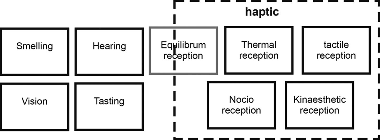
Human senses used in haptic perception. 1
The haptic feedback in the applications
Various applications of virtual reality and teleoperation open many possibilities of using a haptic feedback. The benefits and technical challenges of haptic systems (interfaces) in these areas are significant. Several general application areas are identified in this section. In the medicine, the manipulating by micro and macro robots for minimally invasive surgery and the haptic interfaces for the blind uses the device with haptic feedback. Surgical simulators provide the safe and effective tools for planning and training surgical steps. If the procedures in medicine require physical interaction with the patient, high-quality haptic feedback is very important. An excellent survey on this topic is made by Vander Poorten et al. and Yaqoob et al.
2,3
In the education field, the sense of touch and force feedback can offer large improvements to the existing teaching methods. These improvements lead to increasing the quality of education. The applications with haptic educational systems are developing in the research field, and some noncommercial applications have been developed for different haptic devices. In our research and study, the applications and the device are oriented to robotics and educational purposes. In the entertainment, the force feedback provides the user with a sense of force effects while playing a game (known as Force Feedback Joysticks). This device supports the user and provides them with more realistic interactivity with the game.
4,5
In the industrial applications, the implementation of haptic systems into the CAD systems such a designer can easily manipulate with the constructed mechanical components of the components in the designing environment. In the robotics, the collaborative haptic interface allows the operator to feel the actions made by robots.
6
The haptic application of robot-assisted surgery utilizing magneto-rheological and electro-rheological fluids as haptic actuators is described by Song et al.
7
and Lee et al.
8
and the possibilities of combinations of teleoperation and haptic feedback by Yin et al.
9
Another field is the control of manned or unmanned robots and aircrafts. This gives the human the feedback information about forces acting in controls
10
and structural changes like wing deflection
11,12
or behaviour of aircraft in turbulences like in the study by Ruff et al.
13
Haptic devices could also be used in driving assistance by land vehicles like in the studies by Steele and Gillespie and Liu et al.,
14,15
and the behaviour of the driver response to haptic perception is described by Kochhar et al.
16
Human perception of movement
This chapter focuses on the tactile and kinaesthetic reception. Tactile and kinaesthetic perception is not a static perception. The haptic interaction is divided into two groups. Active haptic interaction where human is able to move objects (e.g. typing on keyboard, playing guitar, piano, etc.). Passive haptic interaction where human is able only to feel objects (surface, vibration, force, etc.).
The passive haptic interaction has a wider frequency range as active, as shown in Figure 2. The limit of the active haptic interaction is not strictly 10 Hz for every human. For example, the speed of typing text on the keyboard can be higher, and a very good typist could hit over 10 keystrokes per second (typing with 10 fingers). The low frequency of perception is also limited, and fully static interaction is nearly impossible to feel. The low frequency limit depends on force and direction affecting the human body. For example, after 1 min of constant acting force, the human is not able to define this force.

Border frequencies fb resulting from an excitation of a simple mechanical model for different materials. 1
Modelling of mechanical systems
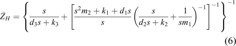
For modelling of mechanical systems, we assume that the operator’s hand pushes/pulls a paddle or moves the paddle sideways (like most controls of machines). In our case, the haptic device is a single axis paddle equipped with the position sensor and torque motor. The crucial parameters are therefore the moment of inertia of motor and paddle and the maximal torque of the motor. The second part of the model is the user itself. This part is more variable, because every human hand is different. 17 The next variable is that every human could grasp the paddle at another radius of rotation. The mathematical model of human grasp is shown in Figure 3.
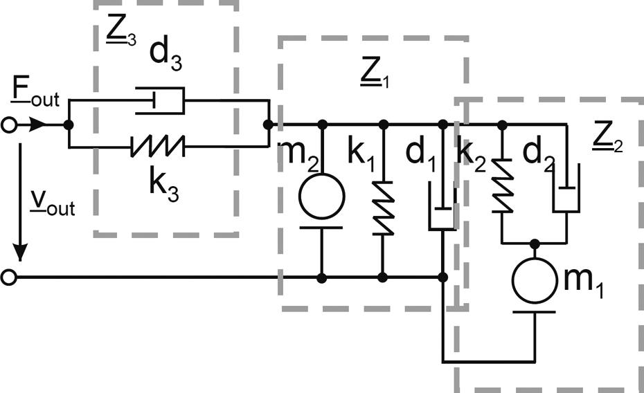
Eight-element model of the user’s impedance – models the passive mechanics for frequencies >20 Hz. 1
Where


This part could be expressed only by statistic values. Figure 4 shows the mechanical impedance of hand movement in the direction like on our apparatus.

Impedance with percentiles (middle) and at different force levels (right) for power grasps of a cylinder (Ø25 mm, defined for 20–400 Hz). 1
Virtual wall modelling
The considered system is a haptic device (paddle) with one degree of freedom. For the other degrees of freedom, the same principle is valid. The virtual wall presents the constraints for the mobile robot. Modelled haptic device consists of a mass being acted by following forces: The force applied by the human user Fuser(t), the force applied by the actuator Fm(t), the force of the damper Ft(t), the force of the spring Fs(t) and the force momentum Fw(t).


where xuser is the paddle position, xwall is the position of virtual wall and x is the distance between the paddle and the wall.

Since the dimensions of the tool are not negligible, we may assume that the tool has a radius r. Then, we have the new paddle position (xuser + r) to be in collision with the virtual wall. And the distance x = xwall − xuser − r
The human force has a positive meaning when it tends to move the haptic device toward the virtual wall. The actuator force and damper force both have a positive meaning when they tend to move the device out of the virtual wall. The damper consists of the piston and the spring. The quantized position signal is sampled with a constant sampling period T. Implementation of the force feedback to the user in the case of the haptic paddle (HP) will be done by an actuator. The actuator will be a DC motor, which provides sufficient force according to the analysis.
A general block diagram of haptic control paddle is shown in Figure 5.
General block diagram of haptic control paddle.
The designed system has five parts, as shown in Figure 6. HP – real environment to touch the virtual wall, the model of the virtual wall, the control system, the motor model and the human model – includes the perception, muscles, joints and skin models and human force Fuser.
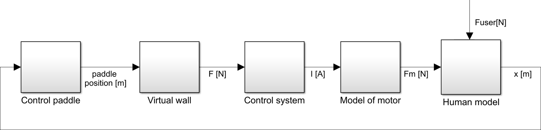
Block diagram of the haptic feedback of the control paddle.
The MATLAB–Simulink model of the virtual wall from equation 10 is shown in Figure 7. We have used a filtered derivative to eliminate the disturbance caused by quantization and sampling.
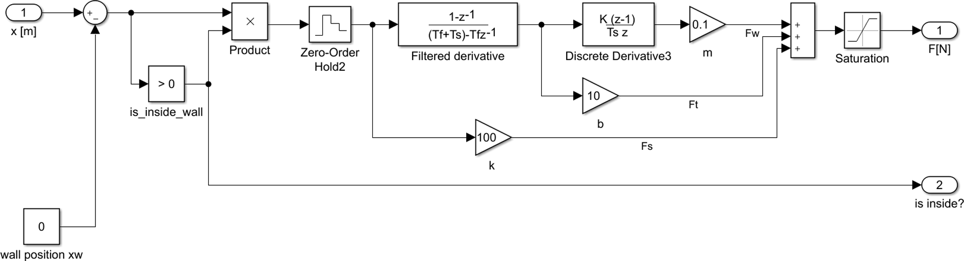
Simulink model of the virtual wall.
The sampling time period used in this simulation is 1 ms. The parameters for the virtual wall were set to k = 100 N/m, b = 10 kg/s and m = 0.1 kg. The result of simulation for sinusoidal input signal is shown in Figure 8(c).

(a) The force of the actuator (left up), (b) the current to the motor (right up), (c) the force of the wall (left down) and (d) the paddle position (right down).
The motor model
To control the torque of the motor, we need to know its torque constant which is the dependence between torque and current flow in the winding. To know the torque constant, we need to measure which force is acting on known lever depending on the current flow in its winding. We have measured the force by load cell IPCouche 0663i on the lever with radius 90 mm from the axis of the motor like in Figure 9. We have controlled the motor by current using the programmable logic controller (PLC) module for motor control X20MM2436.

Dependence between torque and current.
The motor during this measurement (especially by higher currents) produces high amount of heat and its temperature is increasing because it is not rotating (ventilating). During experiment, we have set the motor current and read the force readings. We have tried to connect the motor only for a short while to get it not heated. By higher currents, there was a problem with rising temperature, so we have repeated some measurements after cooling the motor. We have also checked the real current flowing through the motor and created the dependence between the torque of the motor and current. By constant maximal load of the motor, we have observed successive loss of the motor torque. We have also observed similar effect by current measurement, as shown in Figure 10. After cooling down the motor, the maximum current recovered so this phenomenon has not caused any instant or permanent damage to the motor.

Torque behaviour by maximal current.
Torque constant that we have measured is kM = 0.091934134. The time constant Tm of the motor is Tm = 0.0002 s. Based on a known induced voltage, we have also determined the count of pole pairs of the motor p = 1. Constant which defines the dependence of output current from the value which sets the current in output module is kDAC = 6353.469. Motor model in Simulink is shown in Figure 11.

The motor model.
The behaviour of force, motor current, reaction force and the lever position are shown in Figure 8.
The shown disturbances has two sources: The influence of quantization: Depending on the amount of quantization levels, an unwanted behaviour may occur, which we have observed in previous Simulink schematics. Increasing the count of levels (A/D converter resolution) has increased the quality of response in control paddle. To get closer to real wall behaviour, we have utilized analogue input module with 13-bit resolution instead of original 10-bit one. The module is from manufacturer B&R (Eggelsberg, Austria) labelled as X20AI2632. The influence of sampling period: The shorter sampling periods (program execution) are improving the response of the whole system.
Controller design
For the simulation and controller tuning, we use the MATLAB’s Model Predictive Control Toolbox that uses the linear dynamic modelling tool. The controller is shown in Figure 12. The model of the motor is in the state-space representation. The matrices A, B, C and D of the motor model representing the controlled system are obtained by linearizing the real nonlinear dynamical system. This closed-loop control system with constraints produced the control quantity and outputs. It uses the internal model of the motor and solves the optimization problem with the use of the quadratic programming. The solution determines the manipulated variable to be used in the plant until the next control step. Simulated force error between virtual wall output and paddle force output in Simulink is shown in Figure 13.
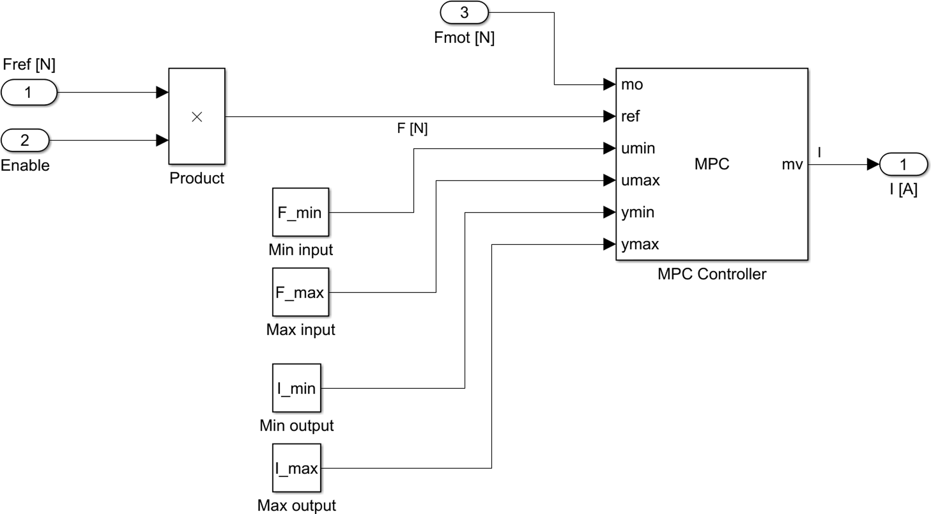
MPC controller in Simulink. MPC: model predictive control.

Simulated force error between the virtual wall output and paddle force output.
System design and realization
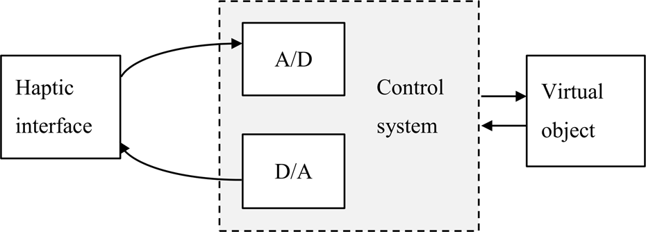
There are several hardware options to build the control system. Control systems based on PLC have desired input–output modules and are fulfilling minimal hardware requirements for the realization of HP. They are also ensuring robustness and applicability in industrial praxis. The block diagram of control software is shown in Figure 14. For control of paddle with haptic feedback with construction like designed, is standard to utilize the impedance type of control, where the input is velocity (position from position sensor) and the output is the force (torque of the motor).

Block diagram of realized control loop.
Based on this assumption, we have designed a control loop. In the block diagram of the control loop, the flow of information is essential. Figure 14 shows the block diagram of the control loop where an open loop impedance control system is utilized. Based on the hardware design, the analogue value which carries information about position is voltage Us from the position sensor. The input module converts voltage to digital value

The realized system is equipped with only one sensor (a potentiometer), measuring the position of the mass of the paddle. Control system uses the arbitrary constant sampling rate and input modules use the 13-bit A/D converter. The motor is controlled by a power amplifier, which is realized in the form of a full bridge. The full bridge is controlled by the control circuit which is communicating with PLC where the control software is running. Since the system is impedance controlled, all HPs are equipped with position sensor, some also have a force sensor to make the closed-loop control possible. The utilized PLC is from type Power Panel 400 (4PP451.0571-75) from company B&R. It has 5.7″ QVGA TFT colour display, 6 program buttons, 16 function buttons and 20 system buttons. It also has a PCI slot for expanding the card. It has 128 MB SDRAM and 512 KB SRAM internal operation memory. Firmware is saved on a CompactFlash card. The frequency of the CPU is 500 MHz. The supply voltage needs to be 24 V DC. The expanding modules are connected using the bus X2X link.
Controller implementation
The model predictive control (MPC) was used to dampen the undesirable vibrations displayed by the paddle. The structure of the system is shown in Figure 15. MPC based on cyclic repeated in finite horizon optimization of a plant model. 18 At the current discrete time k, the current plant state is sampled and a cost minimizing control strategy is calculated (via a numerical minimization algorithm) for a time horizon in the future: (k, k + T). The sampling time period used in this control system is 1 ms. The sampling period depends mainly on the execution time of one control cycle of the PLC. The period has been set to 1 ms due to the computational complexity of the MPC controller. The used PLC requires sampling periods of at least 400 µs. Only the first calculated control action intervention is applied, and the calculations are repeated starting from the now current state again. The MPC algorithm provides the optimal control action useable in many applications. 19,20

The structure of the MPC system. MPC: model predictive control.
In this work, we have implemented the dynamic matrix control method to the PLC which is one of the most common approaches and creates the base of many available MPC products. Control algorithm based on the finite impulse response model obtained from the real system. We suppose the minimization of future errors using the quadratic cost function
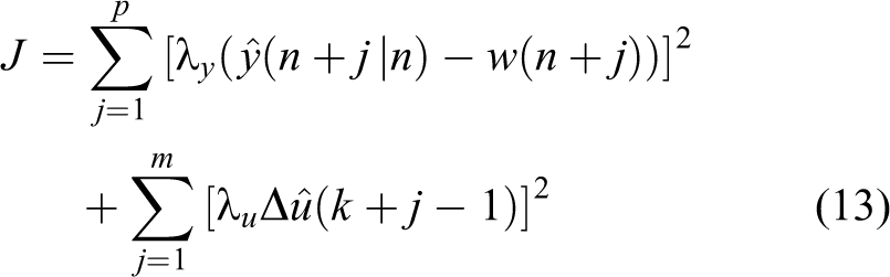
with respect to the system constraints


Where p = 10 is the prediction horizon, m = 2 is the control horizon,
Real system behaviour
Constructed control paddle with the haptic feedback and visualization is shown in Figure 16. Figure 17 shows the difference between virtual wall output and motor force output. This characteristic was simulated in PLC according to known motor model.
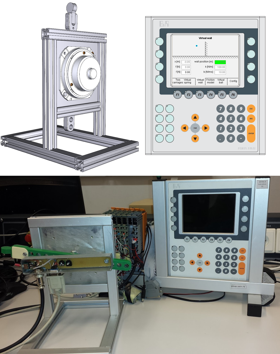
Constructed control paddle with the haptic feedback and visualization on PLC.

Force error between virtual wall output and motor force output.
Figure 18 shows the measured values of the measured current and paddle position with the proportional controller and the MPC controller. The shape of the curve shows the behaviour of the implemented system, including the impact of human impedance and human decision. We can see the effect of the current limit.

Measured data from real system (with proportional controller and MPC controller). MPC: model predictive control.
By comparing the proportional and MPC controller, the proportional one causes peaks in the negative force domain (it holds the paddle in the wall). The current is proportional to the force in the mechanical system. In the case of MPC controller, the transitions are smooth.
Conclusion
We have modelled the system behaviour in MATLAB–Simulink except the mechanical model of human grasp. Human behaviour in the active haptic domain is not easily predictable because users may react differently to the same stimuli, for example, by releasing the paddle at different times and so on. The model of the virtual wall was implemented into the PLC using object-oriented programming. The parameters of the virtual wall can be changed in the visualization (like stiffness k, damping constant b and wall position). The proportional controller is not compensating for the undesired behaviour caused by sampling and quantization. This work described the design approach of the control system for the HP using the model predictive control algorithm. The MPC controller uses the model of the motor for the calculation of optimal control action. By subjective assessment of the HP behaviour, the MPC controls the paddle more accurately than the proportional controller. The MPC is not causing the ‘hold’ by leaving the wall like the proportional controller. Quantitatively, the MPC causes lower force error than the proportional controller. The goal was to create a virtual wall with a response like a real one. The MPC controller makes the paddle behaviour closer to reality.
Footnotes
Declaration of conflicting interests
The author(s) declared no potential conflicts of interest with respect to the research, authorship, and/or publication of this article.
Funding
The author(s) disclosed receipt of the following financial support for the research, authorship, and/or publication of this article: This research work was supported by the following projects: VEGA 1/124/15: ‘Research and development of advanced methods for virtual prototyping of manufacturing machines’; VEGA MŠ SR No 1/0367/15: ‘Research and development of a new autonomous system for checking a trajectory of a robot’; and Slovak Research and Development Agency under the project No. APVV-16-0006: ‘Automated robotic assembly cell as an instrument of concept Industry 4.0’.