
Abstract
Humanoid robots are expected to play a major role in the future of space and planetary exploration. Humanoid robot features could have many advantages, such as interacting with astronauts and the ability to perform human tasks. However, the challenge of developing such a robot is quite high due to many difficulties. One of the main difficulties is the difference in gravity. Most researchers in the field of bipedal locomotion have not paid much attention to the effect of gravity. Gravity is an important parameter in generating a bipedal locomotion trajectory. This research investigates the effect of gravity on bipedal walking motion. It focuses on low gravity, since most of the known planets and moons have lower gravity than earth. Further study is conducted on a full humanoid robot model walking subject to the moon's gravity, and an approach for dealing with moon gravity is proposed in this paper.
1. Introduction
Space robotics technology has played an important role in space exploration due to its advantages of low cost, safety and high performance. Its functionality has improved from Orbiter to Lander, and finally to Rover. Developments in space robotics are aiming to increase robot functionality and their performance in space and planetary exploration missions. The mobility of a space robot plays a major role in reaching the highest expectations regarding the results of exploration missions.
The latest space robotics feature developed in terms of mobility concerns rover design. This provides the capability to move around the surface on a planetary exploration mission. A wheeled robot has many advantages in terms of energy efficiency, easy control of movement and high stability during motion. However, there are some limitations for wheeled robot functionality, such as moving on an uneven surface, overcoming large obstacles and climbing [1, 2]. To overcome the limitations of such rover space robot designs, research has been conducted to develop legged robots for planetary exploration. Legged robots would have the advantages of the ability to climb and move over all types of terrain compared to wheeled robots. However, legged robots require much more complex designs and control than wheeled robots [3]. Some research institutes have developed legged robots for the purpose of planetary exploration missions. However, none of these robots have been used on an actual exploration mission.
Recently, new types of space robots have been developed to perform more complex and efficient tasks. The latest development is Robonaut, which is a humanoid robot developed by NASA. It has successfully been deployed to the ISS to assist astronauts in some tasks, especially tasks that are performed outside the spacecraft (EVA). Such a humanoid robot has the advantages of being able to perform similar tasks to humans, easy interaction with humans, and the use of teleoperation control. It could help to minimize both costs and time, increase safety and work efficiency [4].
For the future of planetary exploration, robot applications are expected to extend to further operations other than scientific work. Robots will perform new tasks such as constructing, assembling and human assistance. The cooperation and interaction between humans and robots on future missions may require robot structural configurations and performances more similar to humans. Therefore, the use of humanoid robotics technology could be useful in such missions and operations. However, the current humanoid space robot feature, Robonaut, only consists of an upper limb. The use of bipedal walking robots system could increase the efficiency of robot performance by overcoming the limitations of using wheeled robots. The development of a full humanoid robot for planetary exploration could be increasingly demanded in the future [5, 6].
The challenge of using humanoid robots in planetary exploration is particularly high due to certain difficulties and limits. Such difficulties include environmental conditions, which should be taken into consideration when developing such a robot. However, many research groups have conducted research on bipedal walking subject to different surface conditions, such as uneven surfaces. Moreover, the effect of environmental conditions, like temperature and pressure, will mostly appear with the robot's hardware. One of the difficult aspects that has not been studied by other researchers is the effect of gravity on locomotion. The effect of gravity on locomotion is an important parameter in developing the motion trajectory. Walking subject to a gravity different to the earth's gravity has only taken place on the moon's surface, as experienced by the astronauts of the Apollo programme. Based on human experience of walking subject to the moon's gravity, it seems to be a significant challenge to walk in low gravity. Therefore, it constitutes an important point to research and develop a system that can overcome the difficulty caused by gravity on locomotion [7, 8].
In this paper, an initial study is conducted to investigate the effect of gravity on biped locomotion. The paper focuses on the effect of low gravity, because most of the moons and planets that are close to earth have lower gravity than earth. The paper has five sections, excluding the introduction and conclusion. Section 2 introduces human locomotion as a first step toward developing a bipedal robot locomotion system. Section 3 shows the control method for robot locomotion and its behaviour relative to different gravities. Sections 4 and 5 analyse the internal and external effects on robot locomotion with respect to different gravities. Finally, Section 6 provides a case study for a humanoid robot walking subject to moon gravity.
2. Human Locomotion
The understanding of human locomotion is a key issue in the development of an effective bipedal robot system. Locomotion is the main method for a human to move from one location to another. Human locomotion is categorized by two gaits - walking and running. The walking gait characteristically has at least one foot connected to the ground throughout the whole motion, while in running there is a period of time where both feet are airborne. The determination of the gait depends mostly on the forward velocity. The running gait is much faster compared to the walking gait. Humans increase their forward velocity during the walking gait until it reaches a certain velocity whereby walking becomes impossible. Upon reaching the maximum walking velocity, the gait is automatically switched to the running gait.
The walking gait is the most frequently used gait for human locomotion. The walking gait cycle, which is the time interval between successive instances of initial foot-to-floor contact for the same foot, consists of two phases: a single and a double-support phase. The single-support phase is when one foot is connected to the ground. The double support-phase is when both feet are connected to the ground.
Running is a natural extension of walking, with significant biomechanical differences. Walking and running are distinguished by the stride duration, stride length, velocity and the range of motion made by the limbs. That is, the kinematics of running differ from that of walking where the joints' motion increases significantly as the velocity increases. The running gait also has two phases - a stance phase and a flight phase. During the stance phase, one foot is connected to the ground, while in the flight phase the whole body is totally off the ground [9, 10, 11].
2.1 Model
Several studies have been conducted to understand the methods and techniques behind human locomotion. In order to study and investigate human locomotion, researchers propose modelling human locomotion as an easy and simple way to get a clear picture of how human locomotion is performed. Modelling in terms of masses, links and joints could demonstrate the characteristics of human motion. Moreover, modelling could provide theories and techniques for locomotion.
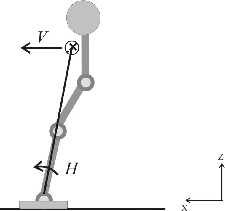
The general method for modelling the human walking gait is the inverted pendulum. The body is supported by the leg and rotated around the ankle joint (Figure 1). This modelled system is considered to be a passive system, whereby dynamic motion depends upon the gravitational force and the body's momentum. In order to complete a one-step cycle, the momentum has to be sufficient to provide forward motion. Moreover, the velocity must not be too large, because the normal acceleration could become greater than the gravitational acceleration that acts in the opposite direction.
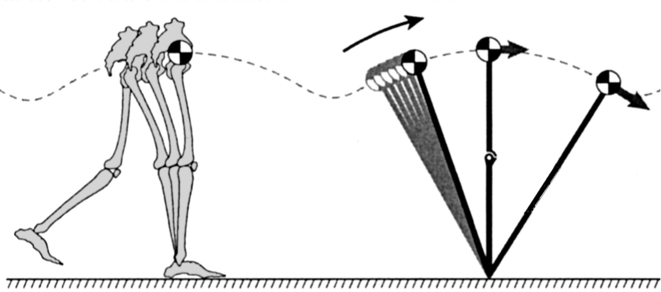
Modeling walking as an inverted pendulum
Human locomotion could be modelled as a mass spring system. The leg acts as a spring that stores potential energy and is released to perform a jump or a forward pushing action during walking or running locomotion (Figure 2). In the running gait, the vertical displacement with respect to the step length is slightly higher compared to the walking gait. Generally, a high stiffness spring could simulate a walking gait while a lower stiffness could simulate a running gait. The high stiffness leg model provides a limited displacement, which is very efficient for walking gait locomotion. On the other hand, a lower stiffness would increase the displacement of the mass, which would result in a higher velocity. Therefore, to model and simulate a running gait, a low-stiffness leg model is used [12].

Modeling human locomotion in terms of a mass-spring system
In the case of low gravity, the gravitational force - which keeps the body connected to the ground – decreases, which may lead to instability of motion. Lowering the forward velocity could increase the motion stability for a walking gait, but the step would take much longer to complete. This could be investigated by using the inverted pendulum model. The modelling of the walking gait is the main focus in the current stage of this research. Clarifying various concerns related to walking subject to low gravity could result in a strong base for the development of a bipedal locomotion system for planetary exploration.
2.2 The Froude Number
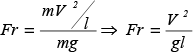
The Froude number is a dimensionless number that is used to describe the behaviour of motion. It is used in fluid mechanics to explain the behaviour of surface waves. Since both surface waves and legged locomotion are dynamic motions in gravity, R. McN. Alexander used it to characterize animal locomotion [13]. The Froude number is the relationship between the centripetal force and the gravitational force, which is determined by:
The centripetal force is generated by the body rotation around the ankle joint. Based on the angular velocity around the ankle joint and the leg length, the value of the centripetal force is determined. The centripetal force always acts upwards in the opposite due to the gravitational force (Figure 3). However, the gravitational force is the only thing that keeps the body connected to the ground surface during locomotion. Therefore, the gravitational force must be greater than the centripetal force in order to have a stable locomotion. The maximum value for the centripetal force for stable motion should be equal to the gravitational force value. By this definition, the Froude number is a positive value that could less than or else equal to one:

The centripetal force and gravitational force acting on the body

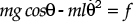
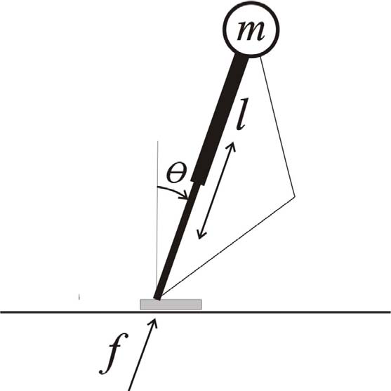
The degree of difference between the centripetal force and the gravitational force represents the extent of the ground reaction force that acts on the foot. The walking gait model in terms of an inverted pendulum is described in Figure 4, and the ground reaction force is determined by:

Model of an inverted pendulum with a fixed length
The maximum value for the gravitational force is when the leg is totally perpendicular to the surface. Eq. (3) could be reformed to show the Froude number as:

The value of (f / mg) could be replaced with the parameter w to indicate the percentage of the ground reaction force in relation to the gravitational force of the body.

The relationship between the Froude number and the parameter w represents the walking velocity vs. stability (Figure 5). As the value of the Froude number increases, the walking velocity increases but the stability of the walking motion decreases. On the other hand, the increase of the value of w represents the stability of locomotion - when the value reaches 1, this means that the bipedal system is fully stopped.

The relation between the Froude number Fr and the parameter w
The walking gait is not always performed in terms of an inverted pendulum with a fixed leg-length. Sometimes, the leg length changes during the walking cycle, which is modelled in terms of an inverted pendulum with a changeable leg length (Figure 6). The leg is fully extended (or at its maximum length) at the beginning of the cycle, and is compressed to its minimum length at the middle of the single-support phase. In this model, the ground reaction force is affected by an additional fact, which is the normal acceleration in the leg. The dynamic equation of this model system is different from the previous model, as below:
Model of an inverted pendulum with a changeable length
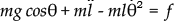
The relationship between the Froude number and the ground reaction force will depend upon the maximum leg acceleration that is achieved when the leg is perpendicular to the surface and at maximum compression. Eq. (6) could be rearranged to:

By substituting (Ï / g) with a in Eq. (7) to represent the percentage of leg acceleration relative to the gravity, (f / mg) with w (in Eq. (7)), and (V2/gl) with Fr, the following equation is formed:

Eq. (8) describes the relationship with the Froude number, the ground reaction force and the leg acceleration. Figure 7 shows the relationship between Fr and w with respect to different values of a.
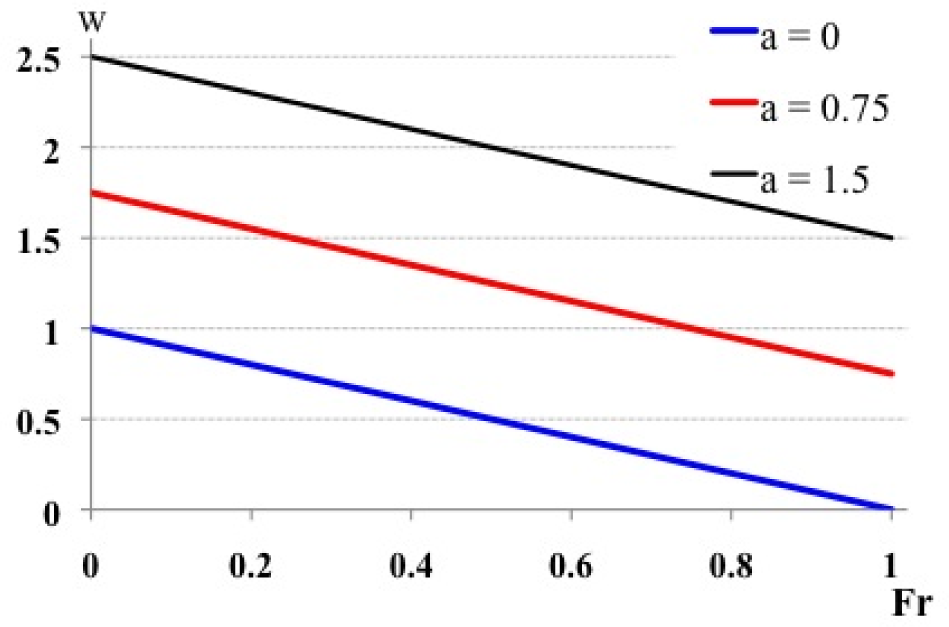
The relation between Fr and the parameter w with different values of a
The maximum velocity of the locomotion can be achieved when the ground reaction force is zero. However, for the safety and stability of the locomotion, it would be better to keep some degree of reaction force so as to keep the body in contact with the surface. Looking at Eq. (6), it can be rearranged to:

The value of (f/ m (g + Ï)) could be assumed to be a constant value, which gives us Eq. (9) in the form:

The variable c could be represented in the same manner as the Froude number. In this form, the relationship between the velocity and maximum leg acceleration is in direct proportion. This shows that the higher the leg acceleration is, the higher the forward velocity that can be achieved. In other words, applying some force from the leg towards the ground can increase the stability of locomotion. However, applying a large force leads to an increase in vertical acceleration, which will cause the body to become airborne. This is particularly applicable in the case of running gait locomotion, but if it is applied in the case of walking locomotion it will most probably switch the gait from walking to running.
3. Bipedal Robot Locomotion
Bipedal walking robots are a key research topic in the development of humanoid robots. Given the fact that humanoid robots have been developed to work in the human environment and interact with humans, they should have the characteristics of humans [14]. The legs are one of the main limbs that categorize human appearance; it is considered to be an important aspect of the development of humanoid robots. Recent research seeks to develop a leg mechanism with the same mechanical features as human legs.
The locomotion control of a bipedal robot is quite complex compared to other types of legged robot systems. Stability is a critical issue in controlling biped robot locomotion. Unlike quadrupedal and hexapod robots, which can control their stability using foot and centre of mass (CoM) positions, a bipedal robot needs to consider more dynamic parameters (position, velocity and acceleration) to perform stable locomotion.
The walking gait is the main locomotion gait used by humans. It has higher stability, safety and energetic efficiency compared to the running gait. Most bipedal robots utilize walking gait locomotion; a few robots can perform hopping or running motions. Most of the research in this field focuses on the control problem as an important aspect of the development of highly efficient bipedal robot systems.
The control methods used for bipedal robot locomotion focus on the dynamics of the body. The zero moment point (ZMP) method is one of the most famous theories used for bipedal locomotion control. ZMP is considered to be highly stable and easy for the trajectory planning of feet, the body position and velocity. However, the ZMP method has the disadvantage of poor energy efficiency because it defines the foot and body trajectory regardless of the joints' load. Another technique used for bipedal locomotion is the dynamic walking method. This technique relies on the body's momentum to provide the walking motion; it was introduced for the first time by Tad McGeer as “Passive Dynamic Walking” [15]. It is considered to be highly energy efficient and can mimic human locomotion. However, this technique is not widely used because of its weak motion control and sensitivity to environmental disturbances [16].
3.1 The ZMP Method
The ZMP is described simply as the point at which the resultant ground reaction force acts. At this point, the sum of all the moments is equal to zero. It is calculated by the equation:

The above equation is used to calculate the ZMP position based on the kinetics of each robot's link (Figure 8). However, there is a simplified method in which the total mass is modelled in terms of a single mass. It is the most widely used method to generate the trajectory planning for the robot trunk with respect to the standing foot (Figure 9). It is essentially determined by:

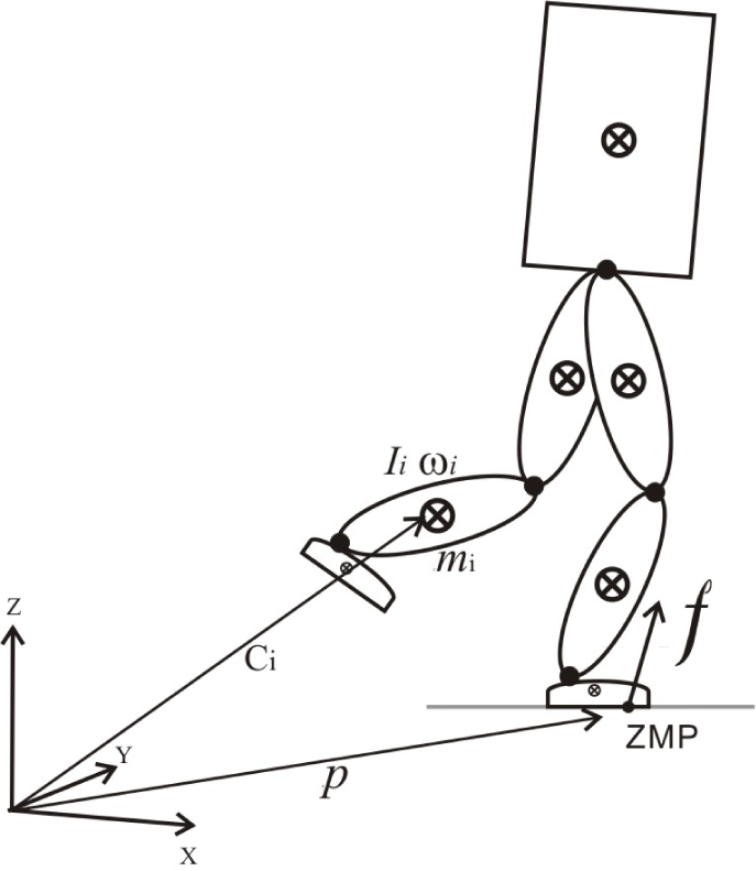
The total reaction force of the whole body and the ZMP location

The simple mode for walking locomotion
In most cases, bipedal robots walk with a fixed hip height. Therefore, the ZMP position is determined by:

Two main aspects directly affect the relationship between the position and acceleration of the robot's CoM. First is the hip height: if the height increases, then the acceleration rate decreases during the step. Second is the gravity, which works in the opposite way, whereby the acceleration increases with an increase in gravity. Therefore, the walking velocity in low gravity is expected to be low due to the lack of low acceleration.
Setting the ZMP locations generates the walking trajectory for the biped robot. The location of the ZMP is also the location where the foot must be placed. Therefore, setting the foot position with respect to time generates the trajectory of the bipedal walking motion (Figure 10). The trajectory of the trunk motion is generated for each step based on the position of the trunk with respect to the foot and the trunk's velocity at the beginning of the step. The ZMP position shifts from one foot to the other during the double-support phase, where both feet are connected to the ground. The movement of the ZMP location might need to take place in quite a short time due to the brief timing of the double-support phase compared to the single-support phase.
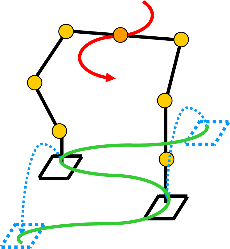
Generation of the walking trajectory for the bipedal robot (Input trajectory: foot trajectory in blue, ZMP trajectory in green; Output trajectory: trunk trajectory in red)
3.2 Behaviour of Walking Motion on a Sagittal Plane
The robot's trunk moves forward during the walking m otion. On the sagittal plane, the trajectory of the motion is determined based on the position of the trunk with respect to the ZMP position and the velocity at the start of the step (Figure 11). The gravity has a direct effect on the walking velocity behaviour during stepping. A lower gravity causes the acceleration and deceleration of velocity with respect to position decreases. It is clear in Figure 12 that the walking velocity in low gravity - one sixth of earth gravity (blue line) - does not increase much during stepping. However, the rate of change in the velocity increases as the gravity increases. It can be seen that there is a significant difference in velocity between the middle of the step and the end of the step during high-gravity walking, namely earth gravity (black line). The same behaviour is seen when checking the velocity with respect to time, as shown in Figure 13. The effect of gravity is also clearly seen on the position trajectory. Figure 14 shows that the distance travelled for a given period of time increases with any increase in gravity.

The initial parameters for one step

The velocity behavior with respect to position for different gravities (lowest velocity = 1.5 m/s)

The velocity behavior with respect to time for different gravities (lowest velocity = 0.5 m/s)
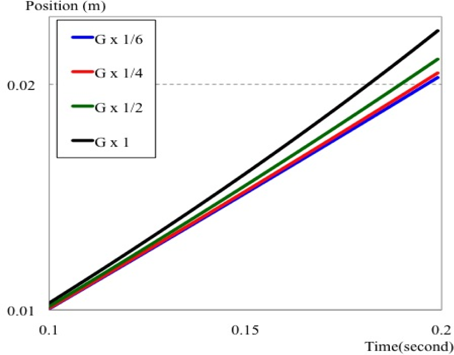
The position behavior with respect to time for different gravities (lowest velocity = 0.1 m/s)
3.3 Behaviour of Walking Motion on a Frontal Plane
The motion behaviour on the frontal plane is slightly different to that on the Sagittal plane. On the frontal plane, the foot is mostly lifted upwards and then placed again in the same location. The trunk moves to the side of the stance foot and returns back its location when the other foot is placed on the ground. This mostly results in a trunk position trajectory in a sinusoid form. The position trajectory behaviour on the frontal plane is unlike that on the sagittal plane, were the trunk reaches the position of the ZMP with its minimum velocity and then accelerates forward. Instead, the trunk moves toward the location of the ZMP until the velocity becomes zero, and then it moves in the opposite direction away from the ZMP position (Figure 15).

Walking motion on the frontal plane.
The motion on the frontal plane is significantly affected by the gravity in addition to the forward velocity (from the sagittal plane). When the forward velocity increases, the time needed for the step becomes shorter. This result in a shorter distance travelled along the sides, on frontal plane,. As the forward velocity decreases as the gravity decreases, the distance travelled on the frontal plane becomes shorter with lower gravity. Figure 16 shows how when a step is taken with the same initial forward velocity and position on the sagittal plane, the distance travelled on the lateral plane decreases with lower gravity. A similar behaviour appears when checking forward velocity with respect to time during one step (Figure 17).
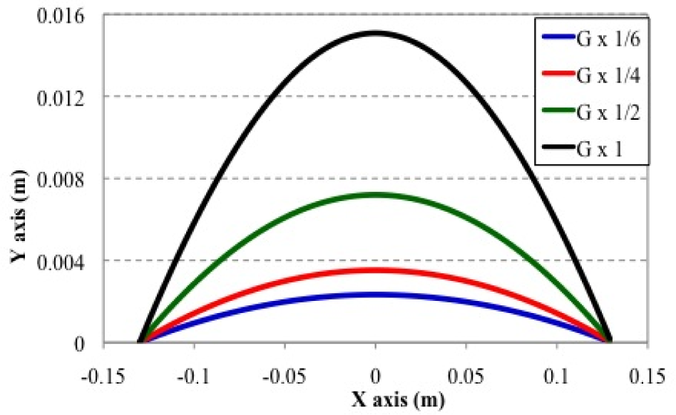
The position trajectory of the CoM for different gravities (ZMP Position: XZMP = 0, YZMP = 0.09; The initial forward velocity = 1 m/s)

The position trajectory of the CoM with respect to time for different gravities (ZMP Position: XZMP = 0, YZMP = 0.09; The initial forward velocity = 0.5 m/s)
4. Internal Effect of the Body on Locomotion
Bipedal locomotion depends greatly on the body's structure. The size, link configuration and mass distribution all determine locomotion behaviour. However, gravity has a direct effect on the body's motion due to the body's weight, which has to be carried during locomotion. Each part's mass in the body produces some degree of momentum based on its motion. The rotation around each joint produces some degree of angular momentum that might affect the locomotion as a whole. Therefore, the mass distribution is an important issue in designing the robot. In the case of space and planetary robots, the internal effects of the body - such as momentum and inertia - have to be carefully considered due to differences in gravity. For example, in low or micro-gravity the effect of angular momentum is considered in particular due to the significant effect it might have on the motion compared to high gravity. Therefore, it is especially important to study the effect of the angular momentum of the bipedal robot system during locomotion.
4.1 Angular Momentum of the Robot Body
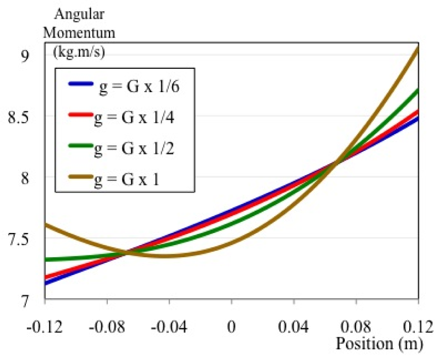
The robot's body consists of many links and parts. When generating the trajectory of the walking motion, it is mostly generated based on a simple model of a single mass and a leg. The angular momentum that is produced by the mass around the ankle joint the ZMP location - and appears to be quite smooth (Figure 18). However, the method of using a simple model for generating the trajectory neglects the motions that are produced by the robot's parts (Figure 19). In the actual robot model, there is angular momentum around the CoM (Figure 20), while the angular momentum around the ankle is not as smooth as it appears for the simple model (Figure 21). The amount of angular momentum that is generated for the robot's parts' motion can affect the stability of the robot locomotion, especially in the case of low gravity.

The angular momentum behavior with respect to position for different gravities (Average velocity = 1.0 m/s, G = 9.81 m/s2)
The angular momentum around the ZMP location for a multi-body robot system
The angular momentum behavior around CoM with respect to position on different gravity (Average velocity = 1.0 m/s, G = 9.81 m/s2)

The angular momentum behavior around the ZMP with respect to position for different gravities (Average velocity = 1.0 m/s, G = 9.81 m/s2)
4.2 Angular Momentum generated by the Swing Leg
During walking locomotion, the swing leg makes a large movement compared to other parts of the body. This is due to the foot travelling from its previous location behind the hip to its new location somewhere ahead. The swing leg has its own mass that rotates around the hip joint (Figure 22). This large movement produces a large amount of angular momentum. The angular momentum of the swing leg increases with an increase in the velocity because the leg has to make a large motion.
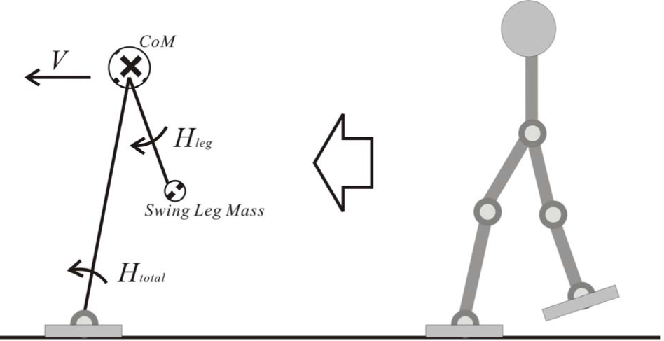
The angular momentum of the swing leg around the CoM and the total angular momentum around the ZMP location for the whole body
The angular momentum of the swing leg around the hip joint is quite large (Figure 23) and has a significant effect around the CoM, the angular momentum around the CoM is larger than the hip joint (Figure 24). The swing leg produces most of the total angular momentum around the CoM (Figure 25) while the rest of the body produces a lower degree of angular momentum (Figure 26). The effect of the swing leg can be clearly seen around the CoM, but it could not have that much of an effect around the ZMP during the walking motion (Figure 27).

The angular momentum of the swing leg around the hip joint with respect to position for different gravities (Average velocity = 1.0 m/s, G = 9.81 m/s2)

The angular momentum of the swing leg around the CoM with respect to position for different gravities (Average velocity = 1.0 m/s, G = 9.81 m/s2)

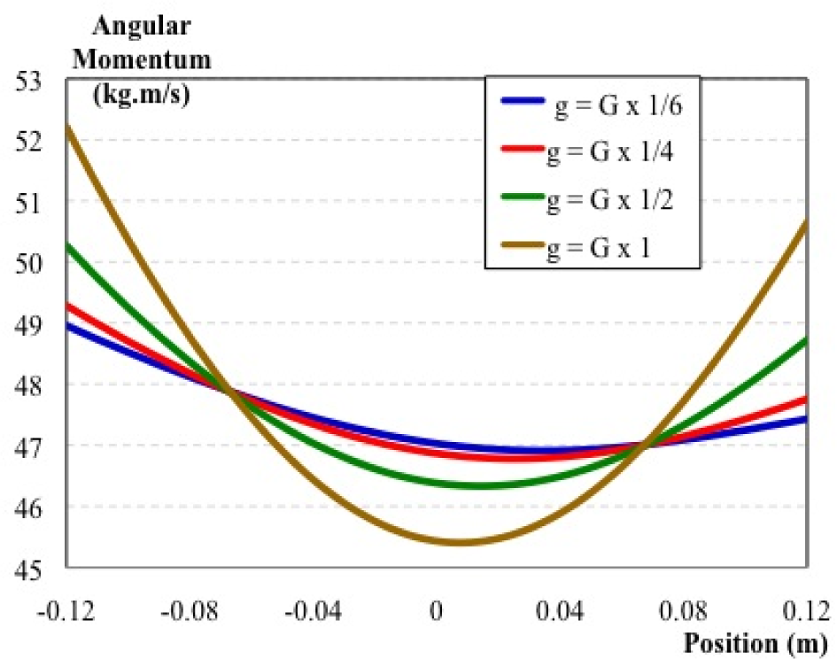
The total angular momentum of the body around the CoM with respect to position for different gravities (Average velocity = 1.0 m/s, G = 9.81 m/s2)

The angular momentum of the body without the swing leg around the CoM with respect to position for different gravities (Average velocity = 1.0 m/s, G = 9.81 m/s2)
The total angular momentum of the body around the ZMP with respect to position for different gravities (Average velocity = 1.0 m/s, G = 9.81 m/s2)
Generally, in designing a bipedal robot, the mass is mostly concentrated on the upper body. The robot legs have a lower mass compared to the upper body. Therefore, the swing leg might not have that much of an effect on the walking motion even in low gravity.
5. Environmental Effects on Locomotion
The planetary exploration robot is expected to deal with many unknown effects during its mission. Due the large differences between the Earth and other planets, it is not easy to know in advance about the real environments and atmospheres of those planets. The robot might have to deal with different temperatures, air pressures, radiation levels, surface condition, and many more unknowns. Most of these effects will need to be overcome through hardware design and the use of special materials. However, in terms of dynamic behaviour for locomotion, it is expected to be affected by several aspects, such as surface friction, slope and obstacles. The biped robot would have to deal with those effects that it might face during its locomotion. Due to the difference in gravity, the dynamical behaviour will be different when dealing with those effects.
5.1 Ground Friction
In nature, the ground friction force is the main driving force for locomotion. The friction force depends upon the normal force that acts vertically to the surface. The tangent force is determined by the friction coefficient μ as:

The value of the friction coefficient is a positive number not exceeding 1, that is:

In order to engage in stable locomotion the horizontal force should not exceed the friction force, otherwise there would be a slipping of the foot during locomotion. The reaction forces on the foot to the surface (Figure 28) are:
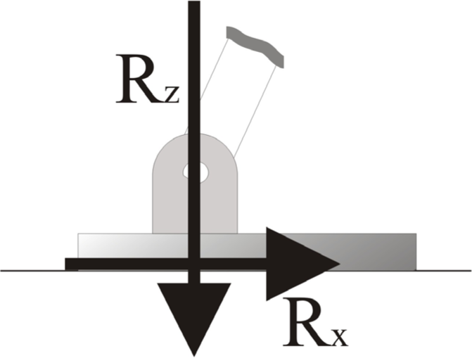
The reaction forces on the foot


The reaction force angle rate that the tangent of the angle is determined by is:

The reaction force angle should be less than the friction coefficient in order to have stable walking. This is determined by:

The vertical reaction force depends upon the gravity. If the gravity is higher, then the vertical reaction force will be sufficiently high for stable locomotion. On the other hand, in low gravity there might not be enough vertical reaction force for stable locomotion. Therefore, the locomotion in low gravity should be carefully controlled.
The bipedal robot walking mostly employs a walking gait with a fixed hip height. The ground vertical reaction force is expected to be constant due to the fixed height of the trunk. However, this reaction force increases with the increase of the mass. In this simple determination, the reaction force rate mostly increases with an increase in gravity (Figure 29). However, in a real walking robot, there is some vertical motion due to the motion of its parts which means that the ground vertical reaction force is not constant. The effect of this motion increases in lower gravity. Therefore, the reaction force rate is higher in lower gravity, unlike the simple model's determination (Figure 30).

The reaction force angle rate with respect to position of a simple model for different gravities (Average velocity = 0.5 m/s, G = 9.81 m/s2)

The reaction force angle rate with respect to position of a real model for different gravities (Average velocity = 0.5 m/s, G = 9.81 m/s2)
6. Study of a Possible Approach for Biped Robot Walking subject to Moon Gravity
The exploration of the Moon is significant challenge for humans. NASA had successfully made nine manned missions to the moon between 1968 and 1972 under the Apollo programme. Recently, several countries including India, China, Japan, the USA and Russia, as well as the EU, are developing manned missions to the Moon. The Japan Aerospace Exploration Agency (JAXA) has proposed a plan to explore the moon using bipedal humanoid robots as part of its new space strategy. The aim is to use Japan's advanced robotics technology to develop and build a moon base and work with astronauts for various operations. For this reason, we conducted further research into the more realistic simulation of humanoid robot locomotion subject to the Moon's gravity. Using dynamic simulation, we can analyse the robot motion of a fully humanoid robot and see the effect of the Moon's gravity on the locomotion.
We used WABIAN-2R, a humanoid robot developed by Takanishi Laboratory, as a model of a humanoid robot exploring the Moon's surface [17]. The walking motion for the Moon's gravity could be performed using the current control method - that is, based on ZMP. The velocity of the walking motion should be decreased due to the low gravity on the Moon. We tested several approaches to develop the walking motion trajectory, as we describe in the following sections.
6.1 Direct Approach for Walking Motion Performance
The direct approach to walking motion is made by using the current control system. In order to have a stable walking motion, the velocity will be decreased. The walking velocity could be a function of gravity for a given walking style by setting the Froude number as a constant value. However, since the leg length is a constant value just like the Froude number, the velocity is the square root of the gravitational acceleration:

For comparison between the velocity on the Earth and the velocity on the Moon, both could be divided as:

By solving the above equation, the velocity on the Moon will be:

Since the Moon's gravity is one sixth of the Earth's gravity, the velocity on the Moon's surface with respect to the velocity on the Earth is as follows:
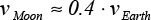
Using the same walking trajectory pattern that is generated based on the Earth's gravity for walking subject to the Moon's gravity, the velocity should be reduced to almost 40 per cent [18, 19].
Simulating the real physical environment of the Moon is extremely difficult due to its low gravity compared to the Earth. Therefore, computer simulation could be an easy approach to simulate robot walking in low gravity. In our research, we use Webots, which is a highly advanced and quick prototyping and simulation program used for mobile robots. We modeled the structure of our robot WABIAN-2R and the simulation environment of the moon [20]. We had conducted simulations of the robot walking in low gravity (Figure 31), and we had shown the data of motion on Sagittal plane in [19, 21]. In this paper we added more data related to the motion of Frontal plane.

Simulation of walking locomotion subject to the moon's gravity
As we had done in [21], we tested the walking motion with different velocities using several values for the control cycle timing. The control cycle is set to 30, 60, 75, 90 and 120 ms. When we ran the simulation of the robot by setting the control step to 30 ms - which is the same as was used for the real walking simulation - the robot slipped due to the high velocity of the leg motion and fell down. However, when the control cycle was set to 60 ms, the robot was able to walk, but with very low stability which made it unable to complete the walking pattern and fell down. When the control cycle was increased to 75 ms, the walking motion was much more stable than the shorter control step. However, when the control cycle was higher than 75 ms (i.e., 90 and 120 ms) the stability of the walking motion increased (Table 1).
Data of several simulations with different control-step times

Looking at the motion in the sagittal plane, the walking motion operates forward in one direction (Figure 32). On the other hand, the motion in the frontal plane operates in both directions. The robot body has to stand on one leg in order to swing the other leg, and then the process is switched to the other leg. Therefore, the motion in the frontal plane takes a sinusoidal form (Figure 33). Due to the internal design structure of the robot, we noticed that the CoM had shifted a few millimetres to the right-hand side at the end of the walking pattern. This issue affected the motion in the frontal plane, resulting in the slippage of the robot to the right. However, the stability in the frontal plane was high when the control step time was set to 120 ms.

Forward position (X axis) for several control-step times
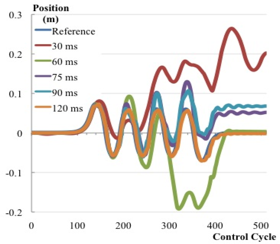
Side position (Y axis) for several control-step times
6.2 Generating a Pattern for Walking Locomotion
The other way to perform a walking gait subject to the Moon's gravity is by generating patterns based on the new gravity. This has little effect on the locomotion in terms of forward and sideward acceleration compared to the direct approach. When generating a pattern with a control cycle time of 75 ms, the generated pattern is just like the pattern generated for the Earth with a control cycle time of 30 ms in terms of position verse control cycle (Figures 34 and 35). This result agrees with the result achieved with the direct approach. However, when generating a pattern with a control cycle time of 30 ms, the result shows that there is a similarity in the forward motion. However, there is a difference in the side motion. The distance travelled to the side subject to the Moon's gravity is less than the distance in the Earth's gravity or with the pattern with a control cycle time of 75 ms (Figure 36).
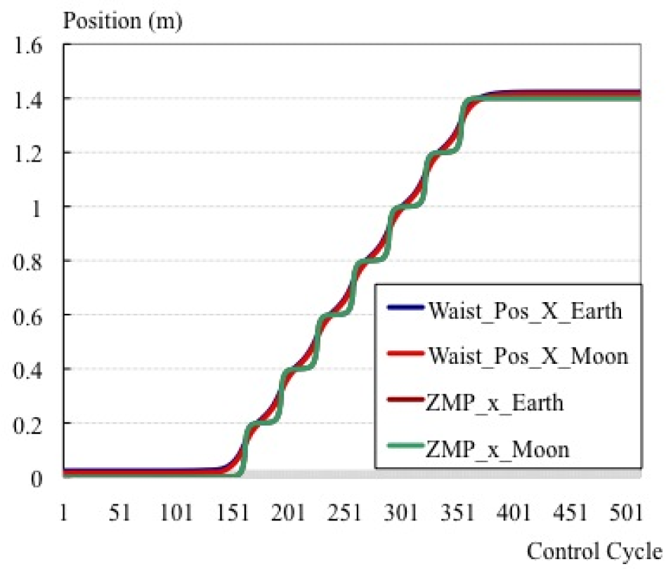
Forward position and ZMP (X axis) of the pattern generated for Earth and Moon gravities

Forward position and ZMP (Y axis) of the pattern generated for Earth and Moon gravities (Moon gravity pattern generated with a 75 ms control cycle)
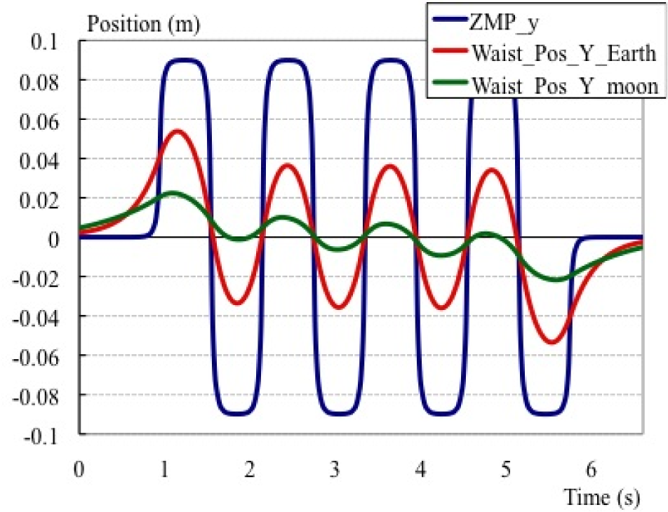
Forward position and ZMP (Y axis) of the pattern generated for Earth and Moon gravities (Moon gravity pattern generated with a 30 ms control cycle)
7. Conclusion and Future Work
An initial study for bipedal locomotion was conducted. The locomotion for a bipedal robot could not be implemented without an understanding of the human locomotion system. One of the methods used to understand human locomotion is by modelling the locomotion gait. The walking gait is modelled in terms of an inverted pendulum and the running gait in terms of a mass spring system. The model could show the effect of gravity and the CoM height on the locomotion behaviour.
In order to perform a walking motion in lower gravity, the walking motion might be different with a higher velocity. At a high velocity, it would be better to switch to a running gait instead of walking. Some internal aspects, such as angular momentum, could have an effect on the walking motion, especially in low gravity. The generation of a walking trajectory based on a simple model might not be accurate because it does not take into consideration the motion produced by the robot's parts.
A possible approach for locomotion control based on gravity is studied. A study plan for the Moon's exploration with a bipedal robot is also considered. The study shows that it is not easy for the robot to walk with a high velocity as is the case on the Earth. Walking with a low velocity in the Moon's gravity is highly stable compared to a higher velocity.
Plans have been made to send humanoid robots to the surface of the Moon in the near future. This research could help to provide for the state of the art of these plans. However, to develop such a robot system, more studies of locomotion subject to the Moon's gravity are needed. This research study will rely on dynamic simulation, currently, due to the difficulty involved in conducting hardware experiments. A research study based on simulation could be a platform for developing a planetary exploration humanoid robot system in the future.
Footnotes
8. Acknowledgments
This study was conducted as part of the Research Institute for Science and Engineering, Waseda University, and as part of the humanoid project at the Humanoid Robotics Institute, Waseda University. It was also supported in part by JSPS KAKENHI (Grant Number: 24360099 and 25220005) and SolidWorks Japan K.K., whom we thank for their financial and technical support. The High-performance Physical Modelling and Simulation software MapleSim used in this research was provided by Cybernet Systems Co., Ltd. (Vendor: Waterloo Maple Inc.).