
Abstract
Compared with the conventional flat foot, the flexible foot is advantageous in implementing human-like walking and much reduces energy consumption. In this paper, from an anatomical and kinesiological point of view, a flexible foot with toes and heels is investigated for a bipedal robot and three critical design parameters for walking stability are drawn, which include stiffness of toes and heels, frontal toe position, and ankle joint position. In addition, a human-like walking trajectory compatible with the flexible foot is proposed by mimicking a human walking pattern. First of all, the zero moment point (ZMP) trajectory continuously moves forward without stopping, even in the single support phase. Secondly, the centre of mass (CoM) trajectory includes vertical motion similar to that seen in human beings. Thirdly, the ankle trajectory follows the rotational motion of a human foot while being lifted from and landing on the ground. Through the simulation study, it is shown that the suggested design parameters can be applied as useful indices for the mechanical design of biped feet; interestingly, the vertical motion of the centre of mass tends to compensate for the transient response in the initial walking step.
1. Introduction
In human walking motion, the two feet play a crucial role in absorbing impact from the ground, maintaining stability on uneven terrains, and helping turning motions. In the same way, the critical design consideration with the foot of a bipedal robot is to enhance walking stability and performance. The study of the robotic foot is purposed to implement a human-like walking motion for biped robots by applying the characteristics of the human foot to the mechanism design. In recent years, several trials of a new foot design with greater flexibility than conventional flat feet have been carried out. For example, Hashimoto et al. [1] designed a sophisticated foot system with an active locking mechanism to keep the horizontal posture of the foot on uneven terrains. Minakata et al. [2] suggested a kind of shoe with a simple array of springs at the bottom to save kinetic energy by allowing lateral motions. Li et al. [3] fabricated a sensor-integrated flexible foot with rubber pads and brushes to absorb the ground impact force. Seo and Yi [4] introduced a bio-mimetic foot which has a close skeletal resemblance to the human foot.
There has been a recent trend in foot design of adopting simple toe and heel joints to follow human ankle motion in landing on and taking off from the ground. First of all, it was confirmed that the flexible foot with toe joints enables increased walking speed and step length [5] and much reduces energy consumption compared with flat feet [6]. Kajita et al. [7] demonstrated that the springy toe is of great use in running and hopping. Along with the mechanical design of the flexible foot, a well-planned walking pattern is required in order to achieve human-like motion. First, by using the heel-contact and toe-off motion of the flexible foot, a knee-stretched walking pattern was generated [8, 9]. It has also been found that the foot trajectory pattern with heel-contact and toe-off motion produces a smoother hip trajectory and increases adaptability to rough terrains [10]. Considering that the flexible foot enables the zero moment point (ZMP) to be moved continuously from heel to toe even in a single support phase as with human beings, a smoothly varying ZMP trajectory was proposed in [5, 11].
These works suggest that adopting toes and heels in the design of the foot mechanism is of great benefit in enhancing the performance and stability of bipedal robots. However, most of these approaches are not matured yet and are lacking in analytical considerations for determining design parameters. Hence, in terms of an anatomical and kinesiological analysis of the human foot, this paper will investigate how to determine some critical foot parameters from the point of view of walking stability. The investigation will include stiffness of individual toes and heels, the position of the big toe, and the ankle position. The flexible foot suggested in section three, where we focus on how to reflect the characteristics of the human foot rather than on the sophisticated mechanical design, is simply equipped with two heels and three toes.
In section four, based on the kinesiology of human beings a human-like walking pattern compatible with the flexible foot is drawn. It consists of the zero moment point (ZMP) trajectory, which moves continuously without staying still at any point in the single support phase, the centre of mass (CoM) trajectory with vertical motion, and the ankle trajectory to mimic rotational motions of the human foot. The numerical results in section five demonstrate that the integrated design approach to foot structure and walking pattern is reasonable in order to achieve human-like walking in bipedal robots.
2. Kinesiology of the Human Foot
2.1 Skeleton of Human Foot
In biomechanics, the functional efficiency of the human foot mechanism to support weight and absorb ground impact has been well investigated. As shown in Figure 1, the human foot has an arch-type skeletal structure which connects heel, toes, and ankle, where the large bone at the heel called calcaneus supports about one third of the load and the metatarsal bones connected to the toes absorb the other impact force from the ground [12]. The flexible tendon on the sole called the plantar fascia ligament is in charge of the structural damping with the movement of the bones by varying the distance between heel and toe. Gefen et al. [13] confirmed that about 38% of impact from the ground is naturally absorbed by the structural characteristics of the foot. It is also known that the division of toes helps to maintain stability while walking during the stance phase by effectively distributing loads.
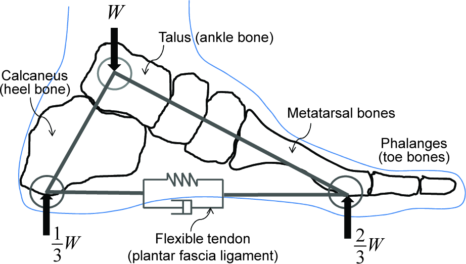
Arch-type skeletal structure of human foot.
2.2 Pressure Distribution on the Sole
In the mechanical design of a robot foot, more than the morphological imitation it is important to consider how to apply the benefits that the human foot brings from a mechanical point of view. During the walking motion, the sole of a human foot experiences pressure change due to the weight and ground reaction. The sole of a human foot mainly consists of three parts: heel part, toe joints (the part where the metatarsal bones end) and the five toes. Figure 2 displays the pressure transition on the sole during a single stride by a standard male as the ZMP is moving forward from the heel to the toe [15]. As shown, the largest pressure is exerted at the heel when the foot strikes the ground. The frontal big toe accepts much more pressure than others when the foot takes off from the ground, which is a reasonable result considering that the centre of mass of the human body is located between the two feet.

Transient pressure distribution on sole during a single stride (standard male) [15].
2.3 Leverage Effect of Ankle
The human foot generates ankle torques to lift the heel as a kind of leverage system utilizing both interoceptive muscle power and exteroceptive self-weight. In Figure 8, BW denotes the body weight, MF is the force exerted at the ankle ligament, EMA is the external moment arm from the toe joint to the BW vector, and IMA is the internal moment arm from the toe joint to the MF vector. Then, the ankle force is determined through the moment equilibrium equation as in [16].

Leverage effect of ankle [16].
Pose variation of the human foot during walking.

Layout of the flexible foot with toes and heels.
Array of toes and heels with built-in spring pillars.

Configuration of the ZMP movement depending on the walking type.

ZMP pattern for human-like walking (period T, step length 2B).

For example, when BW is 150 lb, IMA 12 cm, and EMA 3cm, the produced MF is 37.4 lb, which is equivalent to one quarter of the body weight. In this way, the human foot is enabled to walk with much smaller ankle force than the weight by gaining mechanical profit in terms of the leverage effect. This supports the ankle position always being located behind the BW vector when a human is walking forward, and the ankle force is activated in a direction that minimizes energy consumption.
3. A Flexible Foot with Three Toes and Two Heels
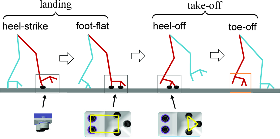
When a human being is walking on a level plane, the left and right foot roughly follow the four steps in Figure 4. After the swing phase of the shifting leg, first the heel strikes the ground and the landing is finished as the centre of pressure is moving forward and the foot is made flat. Then, the heel is lifted and takes off from the ground; finally, the toes depart from the ground. To implement this natural walking in the bipedal robot, above all a flexible foot with the toes and heels separated from the sole is required.
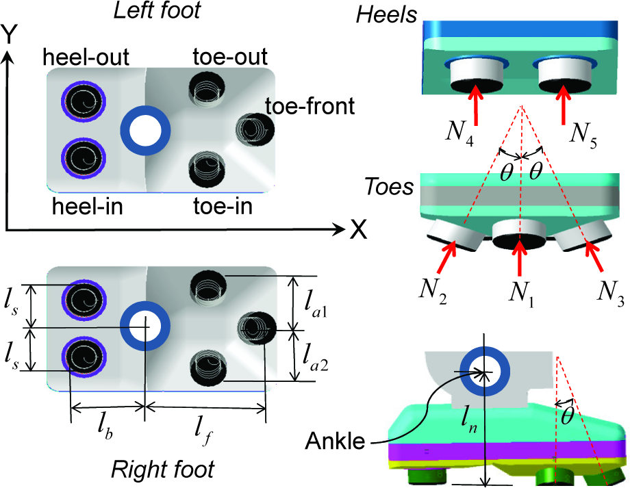
In designing a robot foot, it is unrealistic to mimic the large number of joints of the human foot skeleton as itself, since the kinematics and dynamics of the bones and ligaments are too complex to be controllable. It is reasonable to consider just a minimal number of flexible joints in the foot structure, which is good enough to reflect the main functions of the human foot. As shown in Figures 5 and 6, the flexible foot suggested in this paper has an array of three toes and two heels with independent spring pillars for structural damping, where the three toes form a sort of tripod structure and enable the effective absorption of ground impact in all directions. In [2], it was shown that adopting an array of springs on the sole is advantageous to increase lateral stability on uneven terrains. Given the configuration of the flexible foot, three major design parameters can be raised in terms of the kinesiology discussed in the previous section.
First, it is desirable to determine the stiffness of the individual spring pillars based on the transitory pressure distribution on the sole shown in Figure 2 by following the rule: high stiffness at high pressure and low stiffness at low pressure. Related to this, Kagami et al. [14] adapted toe and heel for their foot design and compared the pressure distribution with the human foot and Ogura et al. [8] has shown that when implementing the heel-contact and toe-off motion in the bipedal walking, the force distribution at the robot foot gets similar to that of human foot. Secondly, as indicated in Figure 2, the big toe of the human foot supports much larger load than other toes when taking off the ground, which means that the frontal toe position in Figure 6 must be shifted to the inside which is close to the centre of mass in the horizontal plane. Thirdly, the leverage effect of ankle implies that its position belongs to critical design parameters for human-like walking.
Since the bipedal robot is a highly nonlinear system consisting of a large number of joints and links, it is very hard to exactly evaluate the influence of an arbitrary foot parameter to the whole walking performance and stability. Hence, the most realistic way to determine the parameter values is to utilize the dynamic simulation for a given bipedal robot model with specific weight, height, and degrees of freedom. For the walking simulation, first of all, a human-like walking pattern profitable to the flexible foot is required, which is discussed in the next section.
4. Human-like Walking Pattern Generation
4.1 ZMP Trajectory for a Flexible Foot
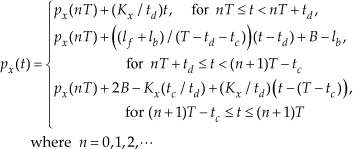
Conventional feet for the bipedal robots are usually flat with rubber pads attached but without flexible toes and heels. Hence, it was inevitable to apply the walking patterns which keep the sole parallel to the ground. In flat-foot walking, as indicated in Figure 7, the zero moment point (ZMP) trajectory is given in such a way that it stays at a point on the sole of the supporting foot and abruptly moves to the opposite foot. However, in human walking, the ZMP is continuously moved from the heel to the toe of the supporting foot. Here, the ZMP pattern indicated in Figure 8 is suggested to achieve a natural walking motion using the flexible foot in the previous section. In the single support phase (SSP) from the toe-off time (td) and the heel-strike time (T
Then, for every step with the same period of time, the ZMP trajectory in the longitudinal direction is given by
and in the lateral direction by
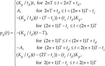
In Figure 8, the discontinuity of ZMP between DSP and SSP was given by considering that the sensor margin of ZMP measurement error, the take-off time (td) and the landing time (tc) do not have to be identical and that the ratio can be adjusted on a kinesiological basis. Since we assume the 11-type pace with two feet in parallel as in Figure 7, lateral ZMP in SSP is fixed, while longitudinal ZMP is still moving. But if a toeing-out pace is assumed, the lateral ZMP can be properly modified. On the other hand, similarly to Figure 8, a continuously moving ZMP trajectory is generated for the single support phase in [11] and a linear ZMP trajectory is also applied for the double support phase in [17]. However, these studies confine themselves to flat-foot walking for flat feet. The ZMP trajectory in (2) and (3) includes the advantages identified in previous works and is appropriate to be applied in human-like walking.
4.2 CoM Trajectory with Vertical Motion
Since a bipedal robot generates the walking motion through the combined movements of all joints, it requires the joint trajectories to follow the desired ZMP pattern. For this purpose, the centre of mass (CoM) Jacobian resolution [17] is very popular and requires the CoM trajectory. To find the CoM position that dynamically matches the ZMP, the linear inverted pendulum model [11, 17] indicated in Figure 9 is desirable, where the following relationship is given.

Linear inverted pendulum model for a bipedal robot.

Since the vertical acceleration is negligible, it can be rewritten as

Now, by following the procedure suggested in [17], the CoM trajectory can be determined by solving (5) for the ZMP inputs in (2) and (3). For the DSP interval, since the ZMP equation was given by the first-order function, we have c̈x(t) = 0 and c̈y(t) = 0, and the above equation (5) means that the CoM trajectory is the same as the ZMP trajectory: cx(t) = px(t), cy(t) = py(t). Also, the ZMP equation for the SSP interval is first-order. However, in order to make the CoM trajectory continuously differentiable for the whole period of time, it is necessary to connect the CoM trajectory with the same slope at the boundaries of DSP and SSP and solve (5) to satisfy the initial and final conditions.
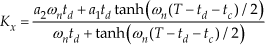
First, for the longitudinal direction with the initial conditions: cx(td) = Kx, c′x(td) = Kx/td and the final conditions: cx(T − tc) = 2B − Kx(tc/td), c′x(T − tc) = Kx/td, we have

with the constraint of
Secondly for the lateral direction with initial conditions: cy(td) = Ky, c′y(td) = Ky/td and the final conditions: cy(T − tc) = Ky, c′y(T − tc) = –Ky/td, we have

with the constraint of

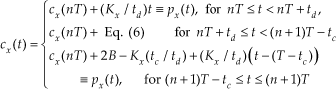
Finally, the longitudinal CoM trajectory for every step can be arranged as
Also, the lateral CoM trajectory for an odd number of steps is given by
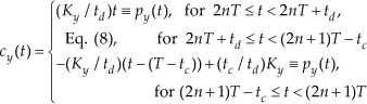
For an even number of steps, it is symmetrical about the horizontal axis.
Thus far, in bipedal walking with flat feet, the CoM position has been fixed in the vertical direction because the vertical motion of the robot was believed to be undesirable for walking stability. However, when a human is walking, it has been observed that the centre of mass naturally sways up and down with small amplitude along with the alternating swing motion of the two legs. The vertical movement of the human body is about 5 cm in the case of a standard male and actually helpful to reduce energy consumption and enable long strides [16]. Hence, we suggest the vertical CoM trajectory as a sinusoidal function:

where cz(0) is the vertical CoM position when one foot starts take-off and D corresponds to the peak of the vertical movement when one leg swings in the air.
Now, when parameters including walking period, step length, take-off time, and landing time are given with foot dimensions, first the ZMP trajectories can be determined by (2) and (3) with the constraints of (7) and (9). This can then be followed by the CoM trajectories in (10)–(12); a specific example is shown in Figure 10.

CoM trajectory for human-like walking (T = 2 sec, td = 0.5 sec, tc = 0.4 sec, A = 0.2 m, B = 0.1 m, D = 5 cm, Cz(0) = 0.935 m, lf = 0.18 m, lb = 0.115 m).
4.3 Ankle Trajectory of the Swing Leg
In human walking, the swing leg goes through take-off, swing, and landing consecutively while the opposite leg is in contact with the ground; the foot pose varies smoothly as depicted in Figure 11(a).

Ankle trajectory of the swing leg in the vertical (sagittal) plane.
This natural ankle motion of human beings has the advantage of efficiently absorbing ground impacts and enables longer step lengths than the flat-foot walking of most bipedal robots. By imitating the human walking pattern for the swing leg, we propose the ankle trajectory described in Figures 11(b) to (d), where the following notations are defined.
tp: heel-off time, td: toe-off time
T − tc: heel-strike time, T − tp: foot-flat time
φtake: take-off angle, φland: landing angle
(xtake,ztake): horizontal and vertical position of ankle at the end of take-off interval.
(xland, zland): horizontal and vertical position of ankle at the beginning of landing interval.
h0: maximum height of ankle
The maximum height of the ankle in the swing phase must be given with a proper value by considering the lengths of thigh and calf and the moving ranges of hip joint and knee joint. For human beings, it the foot arrives at the maximum height when it passes 70% of the walking period and the knee joint is 15 to 25 degrees and hip joint is 50 to 60 degrees [15].
First, the pitching angle of the ankle joint is varied as much as the sum of the take-off angle and the landing angle as in Figure 11(b). To get a continuously differentiable pose, the three intervals are connected with the third-order polynomials:

During take-off and landing the behaviour of the ankle is constrained to its pose; however, in the swing phase it is free in the air. By using simple sinusoidal functions, the horizontal and vertical position of the ankle trajectory can be determined as


where,

5. Numerical Examples
5.1 Biped Simulation Model
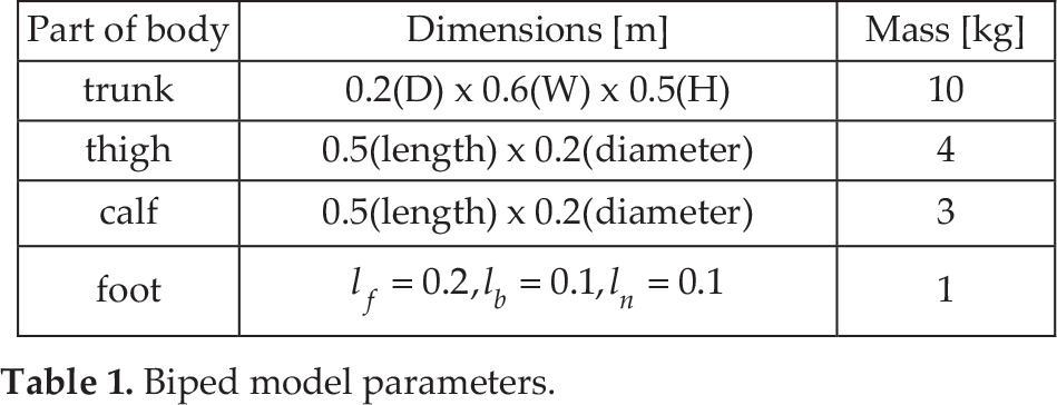
In order to evaluate the suggested flexible foot with a human-like walking pattern, walking simulations are performed with the 12-DOF biped model in Figure 12, where the pelvis of each leg has 3-DOF, the knee 1-DOF, and the ankle 2-DOF; the dimensions are given in Table 1. Basically, a stable bipedal walking can be generated through the movement of leg joints planned to follow the designated ZMP pattern. In [10], for example, the hip joint trajectory and the ankle trajectory were planned first and then the other joint trajectories were determined by considering kinematic constraints. To the contrary, the CoM Jacobian resolution method [17] enables to systematically produce all the joint motions when the CoM trajectory and those of the end-points of all limbs are specified.
Biped model parameters.

12-DOF biped model.
The walking simulation procedure is described in Figure 13, where the joint trajectories are generated as the inverse kinematic solutions for the desired CoM trajectory and ankle trajectory. To establish the dynamical model of the biped and to solve it, the MRS package [18] has been utilized. It is straightforward to trace the CoM position and the joint angles by using kinematic relationships. Also, the ZMP position can be readily found by utilizing the pressure sensor outputs at the heels and toes. In the following numerical experiments, the feedback control loops in Figure 13 are opened and the parameters to generate the three kinds of trajectories are commonly chosen as A = 0.2 m, D = 5 cm, td = 0.5 sec, t c = 0.4 sec, φland = φtake = 150.
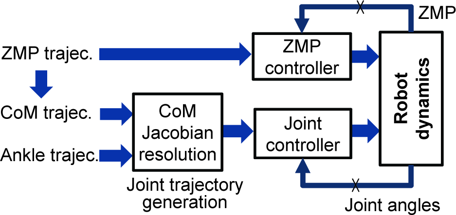
Simulation process of bipedal walking.
5.2 Parameter Study
5.2.1 Stiffness of Toes and Heels
The flexible foot in Figure 5 is to absorb ground impact by toes and heels with built-in spring pillars. In determining the stiffness of the toes and heels, it is reasonable to reflect the pressure distribution on the sole of the human foot in Figure 2, where the pressure ratio between the heel, toe joints, and big toe is approximately given as 6:3.7:1.5. The heel part is equal to heel-in and heel-out, the toe joints to toe-in and toe-out, and the big toe to toe-front in Figure 6. Then, the stiffness of the pillars can be fixed in such a way that their elastic deflections become similar. Table 2 depicts a case where the maximum deflection is 5 mm, where the stiffness of heel-in is 10% higher than heel-out by considering that the inside of the sole accepts relatively larger ground reactions, as suggested in [15].
Stiffness (spring constant) of toes and heels.

While the biped is walking on a level plane by following the ZMP pattern, the reaction forces at the individual heels and toes of the supporting foot are produced as in Figure 14. As shown, the reaction at the heel rapidly increases at around 3 sec because the ZMP is transferred to the supporting foot when the swing foot is taking off. Also, when the swing foot is landing on the plane at around 4.5 sec, the ZMP arrives at the front part of the supporting foot and this results in large reaction forces at the toes. The longitudinal CoM errors are compared in Figure 15 when their ‘distributed stiffness' as in Table 2 and ‘average stiffness' are respectively applied during the four periods of time. It is suggested that walking stability is relatively enhanced when the stiffness of toes and heels is designed on the basis of kinesiology by reducing the deviation from the target trajectory.
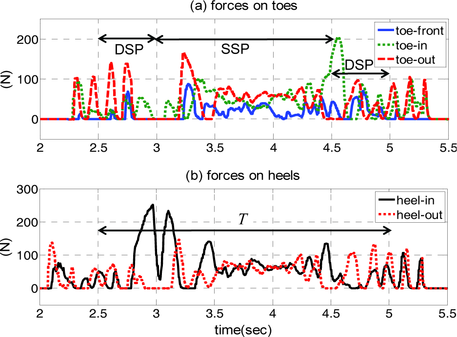
Transition of the reaction forces at toes and heels of the supporting foot.

Comparison of CoM tracking errors (T = 2.5 sec).
5.2.2 Frontal Toe Position
The pressure distribution in Figure 2 implies that the big toe of a human foot plays an important role in bipedal walking and the location would be a critical design parameter. Of the three toes in the flexible foot shown in Figure 6, the frontal toe (‘toe-front’) corresponds to the big toe. Hence, it is necessary to investigate the effect of the frontal toe position. In Figure 16, two cases are compared when the frontal toe is located at the middle (la1 = la2) and shifted to the inside (la2 = 2la1). As shown, when the frontal toe is positioned inside, the ZMP behaviour becomes much smoother, specifically in the lateral direction, which indicates that the walking stability is similarly improved.
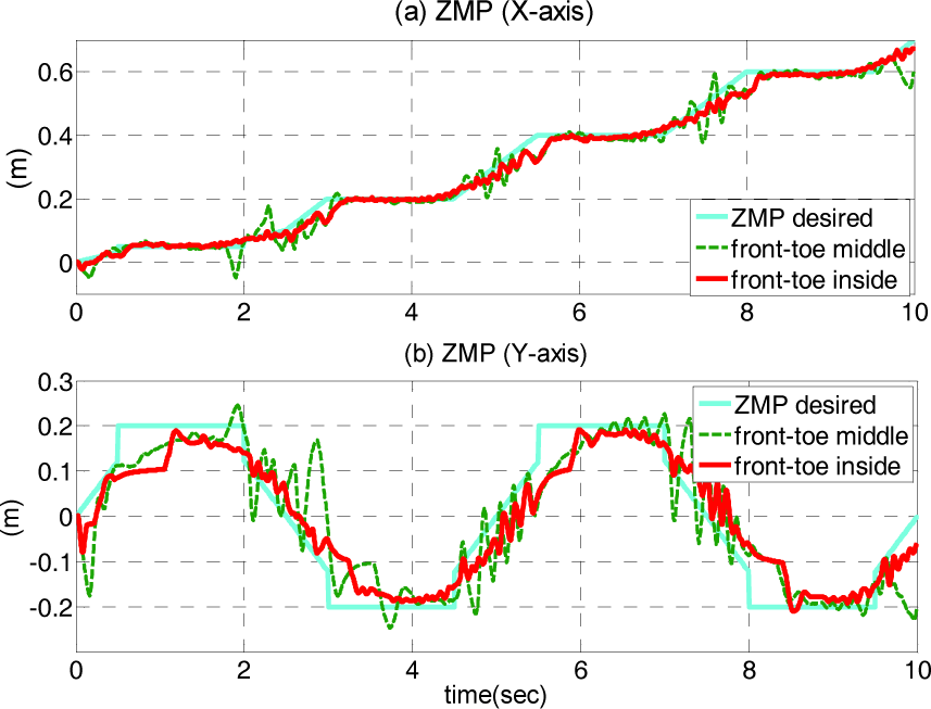
ZMP behaviour depending on the frontal toe position (B = 0.2 m, T = 2.5 sec). Front-toe middle: la1
5.2.3 Ankle Position
As shown in Figure 3, the ankle joint must be located behind the weight vector to exploit mechanical profit due to the leverage effect. In Figure 6, the foot length is divided from the ankle joint by the forward length (lf) and backward length (lb). In fact, the optimal ankle position will be dependent upon the walking pattern with variable step length and walking speed and also physical properties such as height, weight, and the centre of mass of the robot body. Here, with the walking period fixed at T = 2.5 sec, the optimal ratio of lf: lb will be found for the step range of 0.2∼0.4 m by evaluating the ZMP tracking performance.
As a result, the vertical axis in Figure 17 represents the desired ratio of lf/lb, which produces the minimum ZMP error for a specific step length. Roughly speaking, when the step is between 0.25 to 0.35 m a ratio of 7:3 is recommended, and when the step is shorter than 0.2 m or longer than 0.4 m a ratio of 3:1 is preferred. This indicates that it is advantageous in terms of stability to let the ankle position move backward in the case of large or small steps. There is a high correlation between the step length and the human height of a person. Although the above result only represents the biped model in Figure 12 and the specific parameters, it can be applied as a useful index in designing a robotic foot.

Optimal ankle position with respect to the step length variation.
5.3 Effect of the CoM Vertical Motion
The centre of mass of the human body moves up and down as the foot is rotated to take off and land on the ground, and the natural motion of the CoM is known to be helpful in increasing walking speed and step length. Figure 18 shows the behaviours of ZMP and CoM in the lateral direction when the vertical CoM trajectory in (12) is applied and when it is not, where the initial transient response is considerably stabilized by the vertical motion of the CoM. In fact, it is well known that a bipedal robot with flexible modes generates unpleasant oscillatory motion in the initial walking phase, but this has not yet been clearly investigated.
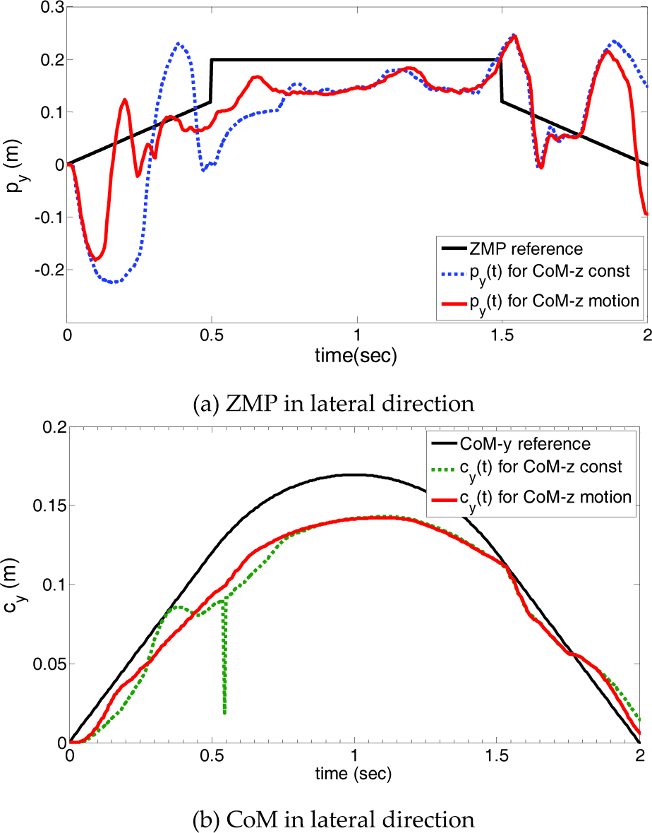
Comparison of the CoM vertical motion(‘CoM-z motion’) with no motion (‘CoM-z const’).
In robotics, usually a bipedal robot is controlled by estimating the CoM motion corresponding to the predetermined ZMP reference. However, in rehabilitation engineering it has been reported that in human walking the ground reaction point (i.e., ZMP) is actively moved reversely to the progress of the CoM in order to regulate the centre of mass speed [19]. It can be confirmed from Figure 16 that in the early initial step, the ZMP retreats a little and then proceeds forward. Yet this intrinsic property of the bipedal mechanism has not been reflected in the ZMP trajectory generation. Here, the dynamical relationship between ZMP and CoM described in (3) can be rewritten for the lateral direction as
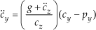
Hence, in order to increase the lateral velocity of the CoM through the acceleration change, the position difference between CoM and ZMP (i.e., cy − py) is required to be increased by moving the ZMP in the opposite direction to the current progress of the CoM. Also, the above equation indicates that when the direction of the vertical acceleration vector is identical to the gravity as denoted in Figure 9, the ZMP movement can be decreased by as much as the magnitude of (g + c̈z) increases, resulting in the reduction of the amplitude of the transient response. After all, when a human is walking, the vertical motion of the CoM induces a moment with respect to the ZMP pivot in order to secure the walking stability, and the same effect can be expected in bipedal robots.
6. Concluding Remarks
As with other biomimetic design problems, it is wise to learn from human beings in designing a robotic foot. In this paper, a kinesiology-based flexible foot and corresponding human-like walking pattern have been proposed for bipedal robots. Compared with flat-foot walking it can be concluded that in order to maintain walking stability and enable faster walking it is helpful to adjust the stiffness of toes and heels, the frontal toe position, and the ankle position. Specifically, the flexible foot is expected to be more advantageous on irregular terrains. The numerical results provide useful information on how to determine the foot configuration and choose the major design parameters.
The flexible foot described in this paper includes many other variables which could affect walking performance and stability. Since the performance of a foot largely depends on the walking pattern, this must be validated along with the walking trajectory parameters. Further studies are necessary to further improve flexible foot design by developing an index to quantitatively evaluate overall performance and stability.
Footnotes
7. Acknowledgement
This work was supported in part by the National Research Foundation of Korea under grant 2012R1A1B3003886.