
Abstract
This project focuses on the design of one robot to help long-time bedridden patients complete their daily leg rehabilitation training while lying in bed. Based on an analysis of many rehabilitation training modes and integrated with a traditional Chinese medicine (TCM) massage technique, a new horizontal lower limb rehabilitation training robot with four degrees of freedom is presented in this paper. The mechanical structural design, kinematic calculation and control system are introduced in detail. A robot prototype is fabricated and rehabilitation training experiments are carried out. The experimental results show that the robot can satisfy the requirements of a variety of rehabilitation training modes and has a certain degree of rehabilitation effectiveness.
Keywords
1. Introduction
With the rapid development of robotics, a robot for rehabilitation treatment has become a focal area of frontier technology in the medical industry. Stroke (medical condition) has a high incidence and high disability rate, and evidence-based medicine (EBM) has shown that rehabilitation has been proven to be the most effective way for reducing the disability rate among stroke sufferers [1]. Rehabilitation therapy can promote the recovery of motor function in patients and its effect and importance have been internationally recognized [2]. Domestic and foreign scholars have applied modern biomedical engineering and robotics technologies to stroke rehabilitation. A rehabilitation robot is an integrated iatrical and mechatronic technology. The intelligent automatic equipment can cover large ranges in training parameter variation, with small adjustment steps to implement various training methods; furthermore, it is easy to maintain consistency by simply re-applying quantitative parameters.
Approximately 795 000 people in the United States annually and approximately 191 000 people in Japan have had a new stroke or recurrent stroke [3]. China's new stroke patients include approximately 2 000 000 people each year [4]. According to the China National Stroke Registry (CNSR), stroke morbidity, mortality and recurrence rate increase with age [5]; therefore, under the current situation of social aging, the number of stroke patients is increasing. At the same time, the trend of cerebral apoplexy is towards younger individuals. According to statistics in the “Chinese Stroke Prevention and Control Engineering Work Report in 2015” by academic Longde Wang, people between 40 and 64 years of age accounted for nearly 50% of stroke patients. Moreover, these individuals occupy 60% of the high-risk stroke population [6]. For acute phase treatment and prognosis improvement, more than 1000 certified stroke centres have been established in the United States, and approximately 150 have been established in China. Rehabilitation nursing is an important part of the standardization of stroke centres [6,7]. In a stroke rehabilitation centre, traditional motor function rehabilitation therapists rely primarily on manual assistance; therefore, a) the rehabilitation effect is determined at the level of physical therapist experience; b) active training is difficult to achieve manually and its training strategies are limited; c) artificial training leads to uncertainty parameters and inconsistent training trajectories and effectiveness. All of these shortcomings restrict the effect and efficiency of rehabilitation training. Robots can meet the need for highly effective, targeted and sustained rehabilitation training, improve efficiency, reduce costs, and realize a variety of active and passive training strategies. Compared to a physical therapist, robot-assisted rehabilitation is clearly a better training method.
Based on the principle of neural plasticity, in order to make the cerebral cortex learn and store the correct movement patterns, repetitive and specific training tasks are to be performed. This is the theoretical basis of rehabilitation treatment. A rehabilitation robot, based on the rehabilitation theory of sport therapy and combined with various rehabilitation training methods, can assist patients with impaired motor function automatically or semi-automatically through complete and intelligent training.
Rehabilitation robots can be divided into two types: the assistant replacement type and the training type, which can be used for upper limbs, lower limbs and hands. According to the body posture of patients undergoing treatment, there is a sitting/horizontal robot, a vertical robot and an aided uprising robot [8]. The most common dysfunction among survivors of vascular disease is paralysis. The horizontal robot is suitable for these cases. The horizontal lower limb rehabilitative robot first appeared at the end of the 1990s. According to their common structure, rehabilitative robots can be classified as either end-effector type or exoskeleton type robots. Single degree of freedom (DOF) and multi DOF structures are included in the end-effector type robot. For example, American/NUSTEP [9], Germany PHYSIOMED Company/THERA-Vital [10], American Restorative Therapies/RT300 Leg [11] and Germany RECK Company/MOTOmed [12] are typical examples of single DOF robots. Typical multi-DOF robots include the Swiss Federal Institute of Technology in Lausanne/Lambda Robot [13], the University of Michigan/Symmetrical lower limb rehabilitation robot [14], the Taiwan National Cheng Kung University/CPM/CAM physiotherapy device [15] and the Harbin Engineering University/Horizontal lower limbs rehabilitation robot [16]. This type of robot usually adopts an electric treadmill structure to complete circumferential treadmill training by following a fixed trajectory. Functional electrical stimulation (FES) is also integrated to achieve the combination of rehabilitation strategies in some of these robots. The structure of the end-effector type robot is simple and only an easy treatment method is available. Many domestic and foreign studies have resulted in the production of mature products in this area.
Exoskeleton robots are generally driven by their leg equipment. The mechanical leg structures are similar to the lower limbs of the human body, with multi-DOF. With feedback provided by multiple sensors, complex rehabilitation training can be achieved [8]. This type of robot primarily includes the Turkey Yildiz Technical University/Physiotherabot [17], the Swiss Federal Institute of Technology in Lausanne/Motion Maker [18], the Japan Yaskawa/TEMLX2 typeD [19], the France/Closed muscular chain lower limbs rehabilitation device [20], the University of Abertay Dundee/NeXOS [21], the Yanshan University/Sitting & lying styles lower limbs rehabilitation robot [22], the Shanghai Jiaotong University/Lower limbs rehabilitation robot [23] and the HeFei University of Technology/Lying style lower limbs rehabilitation robot [24]. Most of these robots are able to treat the hip, knee and ankle joints in the sagittal plane via active training, passive training or power-assisted training via force signal feedback. Another type of robot is based on biological signal feedback, e.g., the Japan Mie University/Biofeedback lower limbs rehabilitation robot [25]. The horizontal rehabilitation robot designed in this paper uses the exoskeletal structure.
Swedish therapist Signe Brunnstrom proposed the famous six-recovery-stage theory [26]. Based on this modern treatment that applies hemiplegic rehabilitation theory, treatment goals cannot rely on a singular solution only. For a robot, a control strategy is provided diversely at different stages of rehabilitation to eliminate abnormal movement patterns. Due to the special theory of traditional Chinese medicine (TCM), internationally accepted evidence-based medicine (EBM) theory is not suitable for evaluating efficacy. However, TCM (including drugs and physical therapy) combined with modern rehabilitation treatment in the case of cerebral stroke is a commonly accepted approach [4]. Currently, the TCM massage technique is performed manually by therapists and there have been no reports that it has been integrated in a robot. Combined with lower limb anatomy, normal horizontal movement posture and the TCM lower limb massage technique are analysed in this paper. Based on clinical application and safety principles, a horizontal lower limbs rehabilitative robot of 4-DOF and its motion control platform, which adapts to different rehabilitative periods, different human heights and left or right lower limbs, are constructed.
In this paper, the key technologies of the horizontal lower limbs rehabilitative robot can be summarized as follows.
Horizontal bone structure. The rehabilitation robot is designed with a 4-DOF mechanical arm and a lifting mechanism to facilitate the realization of the TCM massage maps of lower limb joint actions. In a supine manner, without considering the balance of the affected limb, the robot does not have a weight balancing system; thus, its structure is simple and the control system is easy to implement.
The six types of sports joint rehabilitation training action based on the TCM massage technique. Robots can provide different training patterns according to the physical activity range of the affected limb, such as single joint separation training or multi-joint compound training. With TCM massage on spasmodic muscles provided by the robot, joint activities can be fully expanded.
Targeted treatment options. Due to the different training methods and purposes at different stages of rehabilitation for patients, motion parameters can be adjusted prior to treatment according to the patient's actual conditions. The treatment action remains consistent; thus, the robot can effectively inhibit the lower limb muscle tension, thereby facilitating muscles to produce a harmonious contraction and coordinated movement.
2. Rehabilitation Action Modes
The horizontal lower limb rehabilitation training robot is suitable for patients whose lower limb strength is too weak for them to stand and walk. By keeping up normal joint activity to recover the limb's motion function, joint contracture and rigescence can be prevented. Moreover, joint deformation and muscle atrophy can also be avoided. According to related rehabilitation care and TCM massage theory [27, 28], combined with the characteristics of the robot, the six types of action modes can be summarized as shown in Figure 1.
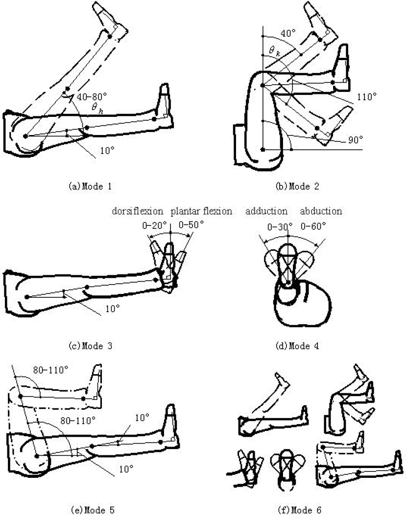
Six types of action modes summarized
Figure 1 describes the joint angles as follows. Hip joint angle θh is defined as the angle between the thigh axis and the body's coronal plane, and knee joint angle θk is defined as the angle between the leg axis and the thigh axis. For the ankle joint in the sagittal plane with motion around the frontal axis, forward motion is called dorsiflexion and backward motion is called plantar flexion; in the frontal plane with motion around the sagittal axis, movement away from the median plane is called valgus and movement close to the median plane is called varus. During actual rehabilitation, according to the specific circumstances of the patient's body, the right motion angles should be chosen. To ensure flexibility of movement and comfort, a hip and knee initial angle of approximately 10° is generally required.
Action mode 1: as shown in Figure 1(a), this mode primarily trains the hip joint. During exercises, the knee and ankle joints are fixed. By changing the motion range of θh, the hip joint is gradually trained. It is beneficial to clear the leg veins and promote blood circulation. In this mode, the maximum range of θh is generally from 40° to 70°, which can be adjusted according to the patient's conditions.
Action mode 2: as shown in Figure 1(b), this mode primarily trains the knee joint. During exercises, the hip and ankle angle are fixed. By appropriately changing the motion range of θk, the knee joint ligaments are stretched. In this mode, θh is usually maintained at approximately 90° and θk can be adjusted in the range of 40°−110°.
Action mode 3: as shown in Figure 1(c), this mode primarily trains the ankle dorsiflexion and plantar flexion. During exercises, the ankle ligaments and calf muscles are stretched. Usually, the dorsiflexion range is from 0° to 20°; the plantar flexion range is from 0° to 50°, which can be adjusted according to the patient's conditions.
Action mode 4: as shown in Figure 1(d), this mode primarily trains ankle adduction and abduction movements while also including adduction and abduction movements of the entire lower limb. Usually, the adduction action range is approximately 0°–30° and the abduction action range is approximately 0°–60°.
Action mode 5: as shown in Figure 1(e), this action primarily trains the hip and knee together, with the trainer's hip and knee bent to a physiological maximum angle of approximately 80°–110°. The patient's action awareness can be reconstructed gradually to effectively prevent muscle rigidity of the lower limbs.
Action mode 6: as shown in Figure 1(f), this action runs sequentially through each action introduced above; this all-around activity trains the patient's lower limb. During continuous training, the motor neural regions of lower limbs can be gradually re-shaped to accelerate recovery speed.
3. Structure Design of Robot
These types of robots are primarily used in hospitals or rehabilitation training organizations, with the service targets being patients; thus, a robot system that is noiseless, air-pollution-free and highly secure is required.
The robot consists of two parts: a mechanical system and a control system. The 3-D model of the robot prototype is shown in Figure 2.

3-D model of robot
3.1. Robot Arm
The robot arm is one type of power-assisted device in the exoskeleton mechanism. A patient's lower limbs are driven by applying aided force instead of using the therapist's arm. It is comfortable to wear and has a compact structure, flexible operation and is safe.
The robot arm consists of three parts: an upper arm, forearm and wrist. It is designed with 4-DOF: the shoulder and elbow with one each and the wrist with two. Each DOF is driven by an AC servomotor. As shown in Figure 3, motor 1 and speed reducer 1 are directly connected and mounted on the base to achieve rotational movement of the shoulder joint. To lower the centre of gravity and reduce the installation size, three other motors and reducers are all connected with timing belts. Motor 2, which is connected to reducer 2, makes the elbow swing. Motors 1 and 2 work cooperatively to complete the trajectory control of the ankle joint in the sagittal plane. The 2-DOF wrist mechanism is driven by motors 3 and 4. Motor 3, which is connected to reducer 3, drives the dorsiflexion and plantar flexion ankle movements while controlling the posture of the foot and lower leg during training. Motor 4, which is connected to reducer 4, drives the adduction and abduction ankle movements while controlling the internal and external rotation of the lower limb. The fabricated experimental prototype is shown in Figure 4.

Mechanical structure diagram of the 4-DOF robot arm

Photos of the fabricated experimental prototype
3.2. Working Principle
The 3-D model, including the patient and robot, is shown in Figure 5. It is clear that the patient's leg is supported by the leg supporter of the robot arm; thus, the rotation axis of the leg is coaxial with the leg support. Moreover, the patient's ankle joints are fixed with the wrist rotation axes of the robot arm. During the system's operation, the patient's calf is tied to the leg supporter with a bandage and the foot is fixed to the footplate with a bandage. The mechanical exoskeleton is driven by motors according to a pre-selected rehabilitation model and causes the lower limb to move; thus, the leg joints are moved according to certain activities in order to achieve the purpose of the rehabilitation exercises.

3-D model, including patient and robot
In terms of structural design, the robot is suitable to train both the left and right legs. In Figure 5, the mechanism is used to train the patient's left leg. To train the right leg, each joint is simply rotated to the opposite position, the footplate is turned 180° and the leg supporter is removed from the support frame, with another pin inserted into the bracket. To adapt to different bed heights, the height of the robot arm can be reconfigured by adjusting the screw in the two vertical guide columns in the body.
For the safety of the rehabilitation treatment, the robot has three preventive measures. First, the limiting mechanism is designed near each joint of the robot to ensure the maximum range of motion. Second, some security measures are taken into account for software. During the period of training, the values of joint angle and torque are compared with the limit values in real time. If overrunning of the parameters occurs, the program will give a quick stop signal. Third, an emergency stop button is set near the patient. If the patient feels uncomfortable, he can quickly press it. To reiterate, the robots contain three security protection measures: software automatic detection, the emergency stop button and mechanical limits. All of these effectively prevent patients from the threat of injury caused by the robot.
3.3. Kinemics analysis
The origin coordinate point of the robot arm o0 is defined at the shoulder joint centre, which is the basic coordinate point of the robot arm's motion control. The human hip joint centre is defined as the origin coordinate point of the human leg motion p0, which is the basic coordinate point of human motion control, as shown in Figure 6. The relative value of the human joint coordinate system and the robot arm coordinate system is (o0x, o0y, o0z). The robot arm is designed in such a way that thigh length is equal to calf length, referred to as L. The patient's weight, height, lower limb joints and bed height are to be measured first. Then, the (o0x, o0y, o0z) values of the robot arm are adjusted to suitable sizes (initial conditions: o0x =200 mm, o0y =477 mm, L=360 mm).
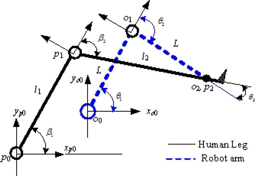
Diagram of joint angles definition in the sagittal plane
For the robot arm, the shoulder joint angle θ1 between the upper arm and the bed is defined as the upper arm axis of rotation. The elbow joint angle θ2 between the upper arm and the lower arm axis is defined as the lower arm axis of rotation. The wrist joint angle θ3 between the lower arm axis and the leg supporter is defined as the wrist axis of rotation. During motion, the calf axis is kept parallel with the leg supporter axis; thus, θ3 is also the angle between the lower arm axis and the calf axis.
For a human, the hip joint angle β1 between the hip and the bed is defined as the hip joint rotation. The knee joint angle β2 between the thigh and the calf axis is defined as the knee joint rotation, as shown in Figure 6. For all joint angles, counter clockwise rotation is considered a positive angle; otherwise, it is negative.
The kinetic equations regarding the p2 point of the human ankle joint are given by:

where β1 and β2 are defined as above and l1 and l2 are the length of human thigh and calf, respectively. The trajectories of β1 and β2 are already known as the target input values; thus, the changing curve of the ankle joint point p2 (p2x, p2y) is determined in the sagittal plane.
The kinetic equations of the wrist point o2 are given by:

The human ankle joint point p2 is always coincident with the robot wrist point o2; this relationship is described by:

The changing curve of the robot arm wrist point o2 (o2x, o2y) can be obtained by using Equation (3); thus, the robot joint inverse kinetic equations are given by:

and

4. Control System
4.1. System Structure
The robot control system consists of a PC as the master and motion control cards as slaves. The communication between the master and slaves occurs through the PCI bus, as shown in Figure 7.

Configuration of an open robot control system
The GT-400 motion control card (Googol-Tech Ltd.) is adopted in the system, which is a four-axis control card that is controlled using pulse or analogue signals. It communicates with servo motor drivers to control four AC servo motors (Yaskawa Ltd.) of small size and strong overload capacity. This constitutes the two level control structure. The first level is the hardware servo control, which is achieved by the servo motor driver. The P and PI algorithms built into drivers are adopted for the current and velocity loops to the AC motor. The second level is the soft servo closed loop control, achieved by the motion control cards for the improvement of position accuracy.
4.2. Control Strategy and Validation
In addition to the traditional PID feedback algorithm, a velocity and acceleration feed forward algorithm is supplemented to the control strategy to ensure dynamic performance and steady-state accuracy, as shown in Figure 8. Gravity compensation, alongside the change in joint angle, is also added to consider the dynamic influence of the robot mechanical system.
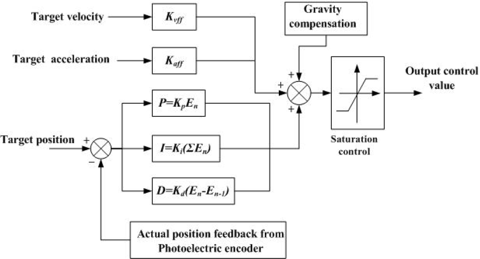
Control strategy block diagram
The algorithm is described by:
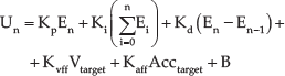
where En is defined as the position error,
Taking the elbow joint as an example, the effectiveness of the control strategy was analysed. Figure 9 shows comparison curves for the position error yielded by the elbow joint motor with 2000r/min.
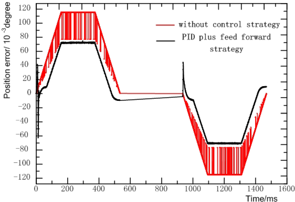
Comparison curves for position errors
With only the hardware servo control (no control strategy), the maximum actual position error was greater than for the software servo control mode. The maximum actual position error was 0.074° with the software servo control mode of the multi-axis controller, which was integrated with PID plus the feed forward control strategy. Position oscillation was greatly decreased because of the feed forward control of velocity and acceleration, as well as gravity compensation. Position precision was improved by the PID feedback plus the feed forward control strategy and the position error increased alongside motor revolutions. For the rehabilitation training of human lower limbs, the error of 0.074° did not affect the rehabilitation exercise. The control strategy therefore met the design target of the robot system. The validity of the control strategy has therefore been verified by the experiment.
5. Experiments and Results Analysis
For passive rehabilitation training mode, six types of rehabilitation actions are provided by this system, as shown in Figure 1. For different patients with unequal lower limb dimensions, the robot needs to have a different range of motion; however, patients' joint motion angles remain the same. According to the patient joint rehabilitation angle required and its lower limb data, each joint motion trajectory of the robot can be planned in advance.
5.1. Initial Condition
Action mode 5 of rehabilitation training, which primarily trains the knee and hip joints together, is taken as an example to describe the experiments. The experiment parameters are as follows: hip joint β1 and knee joint β2 are both changed from 10° to 100°, a single rehabilitation time is 10 s, thigh length is l1=480 mm and the calf length l2=415 mm. As mentioned above, the changing trends of the hip and knee joints are taken as target values; thus, the changing formulae of the hip and knee joints are obtained via polynomial curve-fit. The polynomial fitting curve of the hip rehabilitation angle is shown in Figure 10, in which the velocity and acceleration are smoothly changed while the knee joint is kept constant.
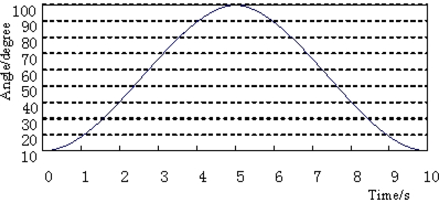
Polynomial fitting curve of the hip rehabilitation angle
After entering the above parameters, the robot arm is moved to the working position, at which the human hip and knee initial angles are both set at approximately 10° for easy movement. The series of photos for action mode 5 during training are shown in Figure 11.

Series of photos for action mode 5 during training
5.2. Experimental results
To plan the human hip joint and knee joint rehabilitation trajectory shown in Figure 8, the actual running tracks of the robot's three joints (the shoulder, elbow and wrist joint) were tested.
The experimental curve of the shoulder joint of the robot arm is shown in Figure 12, where the red line is the target trajectory θ1, calculated using Equation (4) and the black line is the actual position data acquired by the encoder.

Tracing curve of shoulder joint of the robot
From the results, it is clear that the shoulder joint runs smoothly without abrupt change and interruption, with the largest angle reaching approximately 120°. Due to the maximum force and speed required for the shoulder joint, the position error is slightly more than 0.13°, as shown in Figure 13; however, this does not affect the rehabilitation effects.

Position errors of shoulder joint of the robot
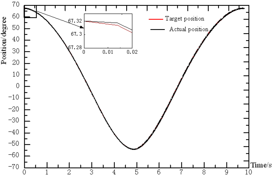
The experimental curve of the elbow joint of the robot arm is shown in Figure 14, where the red line is the target trajectory θ2 and is calculated using Equation (4), while the black line shows the actual position data acquired by the encoder.

Tracing curve of the elbow joint of the robot
From the results, it is clear that the elbow joint runs smoothly with a small rotation change range of approximately 15°; however, movement direction changes three times. The position curve indicates that the elbow joint runs very smoothly, without any vibration and abrupt change. The change curve of the position error is shown in Figure 15, where the maximum position error is approximately 0.016°; this error is able to meet the requirements of rehabilitation action.
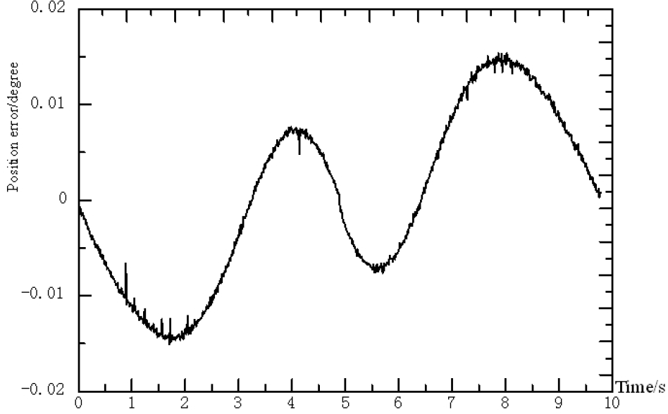
Position errors of the elbow joint of the robot
The experimental curve of the wrist joint of the robot arm is shown in Figure 16, where the red line is the target trajectory θ3 and is calculated using formula (5), while the black line shows the actual position data acquired by the encoder.
Tracing curve of the wrist joint of the robot
From the results, it is clear that the wrist joint runs smoothly with a relatively large rotation change range, up to approximately 120°. Compared with the shoulder joint, the torque needed here is smaller; thus, its actual position error is also smaller, as shown in Figure 17, where the maximum actual position error is approximately 0.055°. The entire position curve is continuous and smooth and therefore meets the requirements of rehabilitation actions.

Position errors of the wrist joint of the robot
5.3. Experimental Analysis
By taking action mode 5 as the typical example above, many experiments have been done in which the mechanical vibration and noise of the system were carefully observed. The experimental data were thoroughly analysed and the following conclusions were obtained:
The mechanical system runs smoothly without singular spots or a great deal of noise. Joints move lightly with non-interference; thus, the robot is able to meet the requirements of the rehabilitation actions.
From the feedback data of the encoders, it was proven that the position errors of the mechanical system were very small, with a maximum error of 0.12°, thus ensuring the accuracy of the system; the tracking curves were also very smooth. The human lower limb joints were able to move to the pre-set angles; thus, the control system is capable of smoothly controlling the set positions and speeds. The mechanical system was also shown to have the ability to implement the six types of rehabilitation actions in a sufficient manner.
During the rehabilitation training process, the patient's lower limb is always comfortable, without being pulled, twisted or applying some other violent action. The entire training process has been verified as extremely safe and reliable; thus, the entire system has been successfully verified.
6. Summary and Outlook
In this paper, the prototype for one type of horizontal lower limb rehabilitation training robot was designed and fabricated. Basic experiments with respect to tracking target trajectories were carried out. The following conclusions have as a result been made.
Combined with the massage techniques of TCM, one new method for horizontal limb rehabilitation training is proposed.
The human-friendly designed mechanical exoskeleton, driven by servo motors with 4-DOF, nearly fulfils all of the lower limb joint actions in the Chinese massage map.
The height of the robot arm can be freely adjusted to adapt to different bed heights and both the left and right legs can be handled by simply re-configuring the arms during treatment.
The control strategy proposed for the human-machine system has been proven to be effective.
In the next step, we will focus on perfecting the prototype and expanding and optimizing the functionality of the system. Human lower limbs have seven DOF; thus, the mechanical system will be improved by increasing the DOF to realize 3-D space rehabilitation training. The active training control strategy will be developed and the effect of rehabilitation in a clinical trial will be assessed.
Footnotes
7. Acknowledgements
The research in this paper was supported by a grant from the China-Japan Technology Cooperation under research project No. 2011DFA10440.
The authors declare that there are no conflicts of interest regarding the publication of this article.