
Abstract
This paper focuses on how to provide mobility to people with motor impairments with the integration of robotics and wearable computing systems. The burden of learning to control powered mobility devices should not fall entirely on the people with disabilities. Instead, the system should be able to learn the user's movements. This requires learning the degrees of freedom of user movement, and mapping these degrees of freedom onto electric-powered wheelchair (EPW) controls. Such mapping cannot be static because in some cases users will eventually improve with practice. Our goal in this paper is to present a hands-free interface (HFI) that can be customized to the varying needs of EPW users with appropriate mapping between the users' degrees of freedom and EPW controls. EPW users with different impairment types must learn how to operate a wheelchair with their residual body motions. EPW interfaces are often customized to fit their needs. An HFI utilizes the signals generated by the user's voluntary shoulder and elbow movements and translates them into an EPW control scheme. We examine the correlation of kinematics that occur during moderately paced repetitive elbow and shoulder movements for a range of motion. The output of upper-limb movements (shoulder and elbows) was tested on six participants, and compared with an output of a precision position tracking (PPT) optical system for validation. We find strong correlations between the HFI signal counts and PPT optical system during different upper-limb movements (ranged from r = 0.86 to 0.94). We also tested the HFI performance in driving the EPW in a virtual reality environment on a spinal-cord-injured (SCI) patient. The results showed that the HFI was able to adapt and translate the residual mobility of the SCI patient into efficient control commands within a week's training. The results are encouraging for the development of more efficient HFIs, especially for wheelchair users.
1. Introduction
The advent of robotics technology in the last two decades has been a revolutionary development. Nowadays, a large volume of heavy-duty and precision work is performed by robots. For example, robotics technology has taken over tasks of human workforces in manufacturing, medicine, psychology, neuroscience, surgery, and communications, and has become a backbone of the modern economic world. However, robotics technology in its present form relies upon human intervention too, engendering a new dimension in robotics research called “robotic interface technology”. Very recently, robotic interface technology has been deployed in automobiles to detect drivers' state of mind by extracting facial, gesture and voice patterns [1]. Equipped with this information the robotics interface interacts with the driver using speech technology to maintain a positive state to avoid accidents. Moreover, due to advancements in biomedical engineering, robotic interfaces are also being researched in robotic surgery and rehabilitation. The greatest advantage of robotic interfaces is perhaps the savings in terms of time and space. These interfaces are free of geographical constraints and can be made available via tele-robotic links anywhere in the world, and beyond.
Researchers over the past few decades have shown a great interest in developing sophisticated robotic interfaces with increased robotic degrees of freedom to support training or the performance of complicated tasks, such as walking [2, 3, 4], minimum invasive surgery (MIS) [5, 6], or multi-joint arm movements [7, 8, 9, 10, 11, 12, 13]. Portable robotic interfaces are also being researched in the form of wearable robotics to allow robotic devices to be used for outdoor activities [14, 15, 16, 17]. Progress has also been made towards control algorithmic development for robotic interfaces, where the goal is to efficiently control robotic devices designed for therapies, where a participant's motor plasticity is promoted through robot-assisted exercises, improving their motor recovery [18, 19].
Robot-mediated therapies and their corresponding robotic interfaces therefore incorporate control algorithms on an ad-hoc basis, where the concept is driven by motor learning, neuroscience and rehabilitation techniques. Robotic interface controls are usually divided into four main categories [20]: assistive, challenging, haptic and non-contact-motivating. These robotic interface paradigms are static, such that they do not adapt to the parameters of controllers based upon the performance measures of the users. Adaptation of control parameters for the robotic interface has the advantage of autonomous tuning of assistance to the changing needs of the users. These robotic interfaces have been termed as “performance-based adaptive interfaces”, and have been used in Lokomat [21] for flexible control strategies [22, 23] and also in collaborative control of electric wheelchairs for safer navigation [24].
To design performance-based adaptive robotic interfaces, one needs to analyse the signals generated as a result of user activity while performing a control task. Analysis of robotic interface signals usually describes the way the user handles complicated tasks whilst controlling the robot-assisted medical/rehabilitation device. In a recent study [25] the signals generated by a joystick user interface were assessed whilst the user was driving an electric wheelchair. Analysis of the robotic interface control, where the users were asked to navigate through different virtual reality environments, led the authors to discriminate between expert and novice electric wheelchair users. In the development of robot-assisted minimum invasive surgical tools [26, 27], a user interface plays a similarly pivotal role in performing reliable surgery. Interpretation of robotic interface signals can lead researchers to design more dexterous robotic end effectors. Robotic-interface signal analysis therefore not only provides a means to assess robot-assisted system performance and skills, it also enables researchers to devise sophisticated robotic-assisted systems.
2. Design and Evaluation of the Hands-Free Interface
2.1. Participants
Six healthy participants (four males, two females, all 20-35 years old) took part in the HFI evaluation experiments. Their participation was voluntary. The experiments were approved by Macquarie University's human research ethics committee.
2.2. Sensor-embedded HFI
A novel sensorized garment was used as an HFI between the human and the EPW. It is capable of producing signals upon unconstrained upper-limb movement as shown in Fig. 1(a). These signals were then mapped onto the two control signals of the EPW to control the navigation commands and speed levels as discussed in Section 3.2 and shown in Fig. 1(b). A critical design feature of the HFI is the presence of a redundant number of available sensors. Consequently each possible body configuration has a distinct representation in terms of signal value [15]. The sensors embedded in the HFI in Fig. 1(a) and were made of a conductive elastomer (CE) material printed on a Lycra-cotton fabric covered by an adhesive mask. CE composites show piezoresistive properties when a deformation is applied [28]. CE materials can be applied to fabric or to other flexible substrates; they can be employed as strain sensors and they represent an excellent trade-off between transduction properties and the possibility of integration in textiles. Quasi-static and dynamical sensor characterization has been done in [15]. Dynamically, CE sensors present peculiar characteristics such us non-linearity in resistance to length transduction and large relaxation times [28], which should be taken into account in the control formulation. During the user movements, HFI sensors detect local deformations on the fabric. As will be explained in the next sections, the signals coming from the HFI will be processed and used for the wheelchair control.

HFI prototype and BoMI framework. (a) HFI covering various body parts. (b) A general framework for BoMI.
The HFI was divided into six sections as shown in Table 1, covering the whole upper human body from back to front as shown in Fig. 1(a). The sensors were smeared on Lycra and created as thick lines connected in series. Every connection between the sensors and the acquisition system was created as a thin line [15]. These connection wires were also characterized by piezoelectric properties. By providing a large set of sensors, a unique representation of the underlying body configuration can be obtained.
The HFI Layout

2.3. Posture Detection and the HFI Calibration
The HFI can detect two similar postures and is able to record a set of distinct postures, coded by the distinct sensor values. This feature can record human body movements as a transition between one posture and another, and are coded as the evolution of the sensor values. We tested the HFI's posture detection capability on a set of distinct postures and the output showed good repeatability and capability, even when the HFI was removed and re-worn by the user. Let
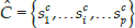
The recognition process during the upper-limb movements requires the kinematic configurations to be detected by the comparison of sensor outputs s with the p columns of the calibration matrix, such that the distance obtained is as shown in the equation below:

where ζi is the distance between the actual sensor readings s and the i-th column of the calibration matrix Si. If ζi is smaller than a certain threshold, the HFI returns the position related to the selected column. In our application, we ruled out the possibility of mapping the entire sensor space values onto the configuration space. This enables the utilization of other norm methodologies, instead of the one defined in Eq. 2.
2.4. Experiments
For performance evaluation of the HFI, the shoulder and elbow joint angles were compared with those from a baseline WorldViz PPT optical system [29]. The participants wore the HFI and three infra-red markers (i.e., one in each hand and one on the back). These were firmly attached as shown in Fig. 3(a). The participants were asked to perform tasks involving upper-limb movements as described in Table 2 and the two simultaneous data sets were collected. The participants performed shoulder extension movements wherein they were instructed to stretch their arms to the chest level as shown in Fig. 2(b) and then to slowly rotate their arms in a curved motion. The participants also performed elbow flexion-extension task movements as shown in Fig. 2(b). The participants were instructed not to move their wrists and elbows during the shoulder abduction movements and similarly not to move their shoulders and wrists whilst performing the elbow flexion-extension movements.

Human upper-limb kinematic model. (a) The arm is modelled as a kinematic chain of six DoFs, which are illustrated by rotation angles. (b) Shoulder and elbow (extension-flexion) movement postures. The blue lines are the trajectories obtained through respective limb movements.

(a) The participant is wearing the HFI, with the markers attached to the body for PPT optical system tracking. (b) The raw sensor data of the HFI from all body parts, the first principal component explaining the body movement and the raw data obtained from the PPT optical system for the same upper-limb movement.
Mean RMSE (deg.), Correlation (r) and Difference in Numbers of Peaks for elbow (Elb.) and shoulder (Shldr.) angles between the HFI and the PPT optical system

2.5. Data Recording
In these experiments, upper-limb abductions and flexion-extensions were measured with the HFI and the PPT optical system. Synchronization of the different systems was controlled by a digital clock signal generated by the computer which recorded the sensor data. The data were captured and stored for both of the systems for off-line analysis.
2.6. Kinematics of Human Arm
The articulated body model of the human upper limb is represented as a geometric hierarchical structure where the articulated body is considered as a series of rigid bodies connected together via joints. This articulated body is shown in Fig. 2(a). In our human articulation model, we use ideal joints to define movement parametrization of human upper-limb movement. The complete upper-limb model will have at least six DoFs defining rotational movements (as reported in [30]). Hence, the shoulder joint is parametrized as a ball and socket joint, whereas the elbow consists of one rotational joint as shown in Fig. 2(a). This choice will enable the reconstruction of kinematics through mathematical characterization.
2.7. Results
The participants performed a set of movements involving their shoulder and elbow joints. Fig. 4(a) and 4(b) represent the flexion and abduction angles (which compound the movement) versus time and the root mean squared errors (RMSE) are shown in Fig. 4(c) and 4(d). Flexion-extension of elbow movement is reported in Fig. 4(a) while Fig. 4(b) represents the evolution of the shoulder flexion-abduction. The continuous curve is the PPT optical system output, while the dashed one represents the HFI response in Fig. 4(a) and 4(b). The plots in Fig. 5 depict the raw signals acquired by the two different sensors and their detected peaks. These signals are sufficient to actuate the EPW relying entirely on the signal principal component (angle) and rising part (peak) value to modulate the control action, as described in sub-section 3.4.

Upper-limb movement signal comparison of both systems. (a) HFI elbow flexion-extension angle estimates compared to PPT estimates. (b) HFI shoulder flexion-extension angle estimates compared to PPT estimates. (c) Comparison of RMSE values for elbow flexion-extension between the HFI and the PPT optical system. (d) Comparison of shoulder flexion-extension RMSE values between the HFI and the PPT optical system.
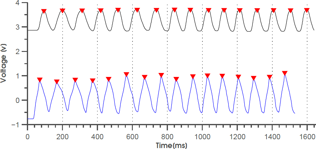
Peak detection of two time series of data of upper-limb elbow flexion-extension movement, obtained from the HFI and the PPT optical system
2.8. Correlation of the HFI and PPT optical system
The results in Fig. 4(a) and 4(b) show elbow flexion-extension and shoulder flexion-abduction sensor output from one of the experiments using the HFI and the PPT optical system, respectively. A correlation coefficient r and RMSE was calculated between the angles obtained from the HFI and the PPT optical system as tabulated in Table 2. On average, the RMSE was less than 2.1° for all arm angles and the correlation coefficient varied between
Correlations between time series of shoulder movements for the HFI and PPT were strong (mean = 0.85, SD = ±0.083). The correlations were considerably high between the HFI and PPT for the time series of elbow extension-flexion movements, and there was also a significant relation between the number of peaks, as tabulated in Table 2. The results obtained correspond to what we expected. Elbow and shoulder readings are determined by lower- and upper-arm-joint activity, respectively, which do not necessarily occur simultaneously. The peaks detected as shown in Table 2 were the function of space dimensionality reduction of HFI signals and the normalized data of the PPT optical system, involving the shoulder and elbow joint movements. It was revealed that most of the variation in HFI signals could be explained by the first principal component. Peak detection was performed on the first principal component of the candidate movement signal obtained from the raw HFI data. The principal component is a linear combination of an unknown number of original features [31, 32]. Resolving one principal component therefore indicates that one feature from the original feature space is required to replicate the information contained in the full set of signals. The presence of the mean number of peaks in the HFI feature space was not significantly different to the PPT optical sensing space across all subjects, as shown in Table 2.
3. Wheelchair Navigation with Residual Body Motions
3.1. Participant
A 25-year-old SCI male adult participated in this preliminary (pre-clinical testing) study. The participant was right-handed, had normal or corrected-to-normal vision, and volunteered for the experiments. The experimental protocol for testing and selection of EPW controls with persons with disabilities was approved by the university's ethical committee for human research.
3.2. Experimental Set-up
The participant was asked to sit comfortably in front of a virtual reality (VR) system as shown in Fig. 6(a) and 6(b), while wearing actively-switched goggles synchronized with the VR projection system to provide a 3D stereo view of the artificially generated images. The participant was provided with the perspective view of the EPW. The static targets and path lines were defined in the scene to help him navigate the EPW around the obstacles. Obstacles were geometrical shapes, depicted as walls and corridors placed along the straight path connecting the initial position of the subject to the target. The simulated EPW could collide with and go through obstacles. A brief flash of light indicated that a collision had occurred.

Virtual EPW navigation experiments. (a) Virtual EPW line-following navigation trials. (b) Participant's upper-limb movements for controlling EPW.
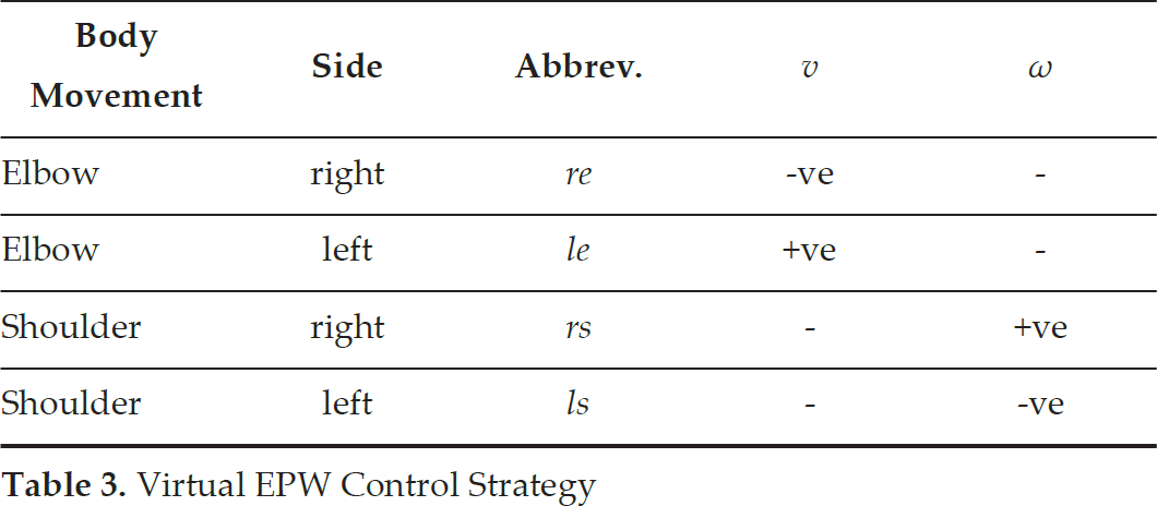
The virtual EPW is controlled firstly by the linear speed, which can be positive (forward) or negative (backward), and secondly by the rotational speed, where positive means anti-clockwise (leftward) turn and negative speed means for rightward turn. We formulated the control as a “command vector”,
Virtual EPW Control Strategy
3.3. Data Recording
The HFI signals were recorded for the shoulder and elbow movements with a 64-channel amplifier (National Instruments DAQ) in differential configuration. The 52-channel high-density HFI covered the whole upper body. The signals produced upon the movement/s were amplified, bandpass filtered and then sampled at 20-48 Hz by a 12-bit A/D converter.
3.4. EPW Control Scheme
The HFI signals were collected during the movements and were rectified and filtered using principal component analysis (PCA) [31, 32], which was normalized to the average sensor signal recorded for the participating joint during maximum arm abduction or flexion. To remove possible drift and noise artefacts from the HFI signals, we used the control scheme shown in the signal flow diagram in Fig. 7. The time derivative of each of the four principal components (PC) was calculated and a dead zone was applied to each of them. The signals were then positive-rectified, as we are only interested in the rising part of each PC (see Fig. 7). The processed signals from the two elbows were then subtracted from each other to generate the translational velocity, while the processed signals from the two shoulders were subtracted from each other to generate the rotational velocity (see Fig. 7). The output of the processed signals (i.e., the EPW controls) were sent to the virtual EPW by using a user datagram protocol (UDP) connection. The signal outputs (v and ω) obtained during one of the navigation experiments are shown in Fig. 8(a) and 8(b) while the participant attempted to follow the prescribed trajectory as shown in Fig. 8(c).

Block diagram and signal flow graph of the HFI to EPW control

EPW control scheme output. (a) Signal output for translational velocity
3.5. Results
The participant wore the HFI and was seated in front of a VR system as shown in Fig. 6(a) and Fig. 8(c). A thick white line was marked on the floor and the participant was asked to navigate through the corridors and doorways following the line as shown in Fig. 6(a). The participant first familiarized himself with the EPW control scheme through arm and shoulder movements. Upon completing this initial step, the participant was instructed to start following the prescribed path (also shown in Fig. 6(a) and 6(b)). The participant moved in different directions in the virtual environment to learn the control criteria. As the participant spent more time moving in the virtual scene, his understanding of the control map improved and he was able to navigate the scene with greater accuracy. The data were recorded simultaneously while the experiments were conducted. At the end of every experiment, two trajectories were plotted (as shown in Fig. 8(c)). In the resulting plots, the black line is the participant's trajectory whereas the blue line is the prescribed trajectory. We measured the subject performance based upon two indicators: the mean “trajectory error” and the number of “intersecting points”, with the baseline as shown in Fig. 9(a) and 9(b), respectively. The data in Fig. 9(a) shows a monotonic reduction in the subject's trajectory error from trial to trial. This is consistent with the hypothesis that, through practice, a subject is able to adapt to their environment using the novel control strategy of moving an EPW with shoulder and arm movements. The increasing trend in the number of “intersecting points” is evident for the overall number of trials as shown in Fig. 9(b). The results in Fig. 9(a) show the mean trajectory error of the participant for each week's trial in reaching the prescribed endpoint from the starting point. The drastic reduction in trajectory error between the first and second week's trials shows that the participant's initial mobility adjustments were significant. In subsequent trials, the participant's movement adjustments are more finely tuned because the participant's familiarity with the HFI control plan improves, resulting in smaller trajectory errors.

EPW navigation experimental results using the HFI with control strategy defined in the above sections. (a) Average navigation trajectory distance error shown for every week's trial. (b) Mean number of intersection points and the increasing trend over the period of time.
4. Conclusions
The possibility of controlling powered mobility devices with elbow and shoulder movements has been presented. Experiments were conducted to evaluate the hands-free interfacing paradigm and the outcomes were consistent with user reliability factors and short-time response requirements of the body-machine interface technology.
The study examined the correlation of kinematics that occur during moderately paced repetitive elbow and shoulder movements for a range of motion. The correlation between HFI signals and PPT measurements was strong. The correlation counts across the activities involving the elbow and shoulder movements were 0.94 and 0.85, respectively. It was found that in the phase of movement as shown in Fig. 4 and Fig. 5, both measurements follow a common sinusoidal wave pattern with a small time lag. In Fig. 5 PPT and the HFI both give increased and decreased counts of peaks upon increasing and decreasing the movements, reflecting increased and decreased joint angle activity.
The kinematic variation of human upper-limb movement is consistent with two features of the HFI (i.e., angles and peaks), which is additional evidence of accurate identification of BoMI control within HFI signals. The identification of upper-limb flexion-extension in the experiments, as one of the most relevant features of the HFI with respect to kinematic motion, is consistent with previous studies that aimed to reconstruct movement trajectories accurately with rectangular waves [33, 34].
This study also examined the possibility of using a hands-free interface for powered mobility devices such as electric-powered wheelchairs. Our approach was based on the key concept that the burden of learning to control powered mobility devices should not fall entirely on the people with disabilities. In this case, “learning the user” means learning the degrees of freedom in which the user is able to move most efficiently, and mapping these degrees of freedom onto EPW controls. Here, we should stress that such mapping cannot be static, because in some cases users will eventually improve with practice. Disability may also be progressive, meaning the mobility of the user gradually deteriorates. In both situations the BoMI must be able to adapt and to update the transformation from body-generated signals to efficient patterns of control. The final aim is to facilitate the formation of new and efficient maps from body motions to control space.
In this work, we have successfully demonstrated that information from the HFI signals during voluntary elbow and shoulder movements can be utilized. As evidenced from the evaluation experimental results, the parametric space of the HFI signals correlated well with variations in global kinematics of natural elbow and shoulder movement morphologies.
The residual body signals can be utilized to produce a set of commands to control powered mobility systems, e.g., EPW, which belong to a general class of robotic-interface systems. These systems are critical to improve the quality of life of people with limited degrees of freedom in their movements in everyday life. The participants' movements were tracked with an optical device in parallel as a baseline comparison. Our findings show that the correlation between the HFI signals and optical tracking was strong, with minimal time lag between the time series. We also found supporting evidence that, along with the upper-limb movement angles, the peak signal is a highly informative feature. In conclusion, HFI technology can be utilized to access the natural pathways of uninjured regions in the SCI or stroke population, and can be consequently used to design reliable and quick-response control interfaces for EPWs.
5. Future Work
Possible areas of future research which emerge from this paper include:
Design more robust control strategies and construct more efficient tuning techniques for adjusting the parameters of the calibration matrix.
Further research on learning algorithms and their application in unstructured residential environments.
Larger studies including recent and chronic SCI and stroke patients and a control group.
Further multidisciplinary experiments in healthy subjects and stroke (and SCI) patients to specify the rehabilitation indications of this device and modes of control for stable driving purposes.
Footnotes
6. Acknowledgements
This publication was made possible by the support of an NPRP grant from the Qatar National Research Fund (NPRP# 4-368-2-135). The statements made herein are solely the responsibility of the authors.