
Abstract
This article aims at flying target detection and localization of a fixed-wing unmanned aerial vehicle (UAV) autonomous take-off and landing within Global Navigation Satellite System (GNSS)-denied environments. A Chan-Vese model–based approach is proposed and developed for ground stereo vision detection. Extended Kalman Filter (EKF) is fused into state estimation to reduce the localization inaccuracy caused by measurement errors of object detection and Pan-Tilt unit (PTU) attitudes. Furthermore, the region-of-interest (ROI) setting up is conducted to improve the real-time capability. The present work contributes to real-time, accurate and robust features, compared with our previous works. Both offline and online experimental results validate the effectiveness and better performances of the proposed method against the traditional triangulation-based localization algorithm.
1. Introduction
In the past few years, the integration of advanced robotic technologies with unmanned aerial vehicles (UAVs) opens new fields of applications. The opportunities and challenges of this fast-growing field were summarized by Kumar et al. [1]. Safe and autonomous motion control is shown definitely essential for various tasks. Within unknown or Global Navigation Satellite System (GNSS)-denied environments, autonomous navigation is an important component. Especially, autonomous take-off and landing has been of most importance as one of the most critical phases in many mission profiles of fixed-wing UAVs. Even small errors in guidance and control could yield system damages or even lost.
Besides GNSS and Inertial Measurement Unit (IMU), vision-based navigation has absorbed more attention from researchers in fixed-wing UAVs and quad-rotors as well. Both ground and onboard schemes have been developed for vision-based navigation. These onboard applications based on rotary-wing aircraft [2–4] and fixed-wing aircraft [5–8] configure a single camera or multiple cameras on the aircrafts to detect runway or cooperative object for self-localization. Compared with onboard navigators, the ground system possesses stronger computation resources and saves cost because only one navigator is needed in each airport runway. Moreover, the ground scheme concentrates on autonomy of aerial vehicles' take-off and landing on the runways.
Generally speaking, the ground vision-based autonomous take-off and landing has been mainly employed into fixed-wing vehicles [9]. LED-like visual fiducials are assigned onto UAVs to highlight the flying vehicles in images.
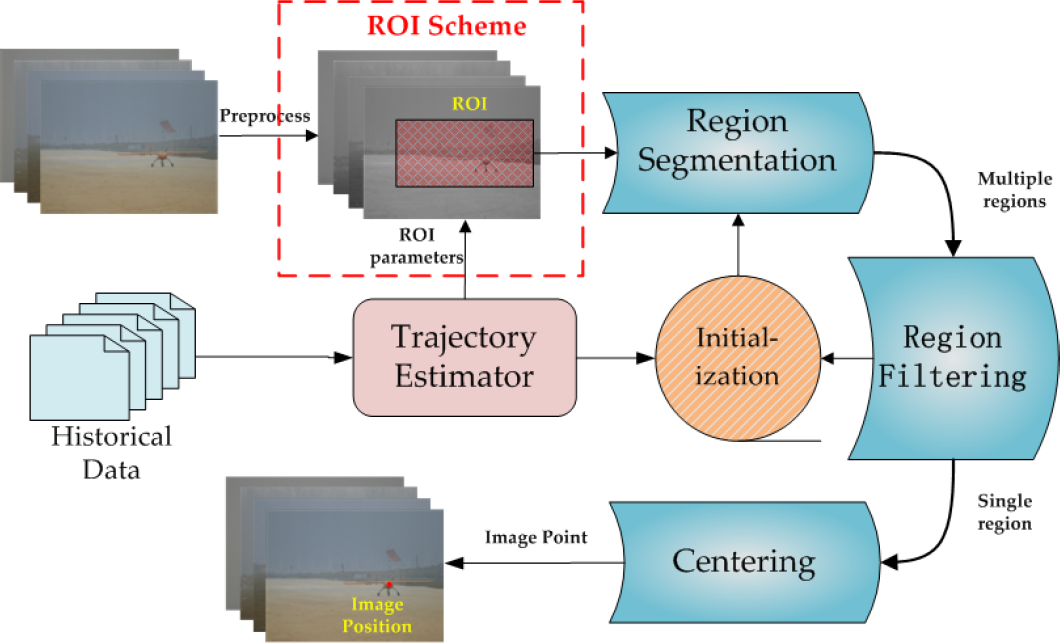
Aiming at runway take-off, taxiing and landing of medium/large aerial vehicles, a ground stereo vision system has been developed and implemented in our previous works [10–15]. The system architecture and components are shown in Figure 1. Two cameras are symmetrically located on independent Pan-Tilt units (PTUs) to capture flying aircraft images. The PTU is controlled and feeds the pitching and yawing angles backward. Target detection of captured sequential images is accomplished by the specified computer. The three-dimensional localization algorithm is conducted for real-time online spatial estimation of the flying vehicle. In particular, the two PTUs are allocated on both sides of the airport runway to enlarge the baseline. It contributes to promoting the localization accuracy.
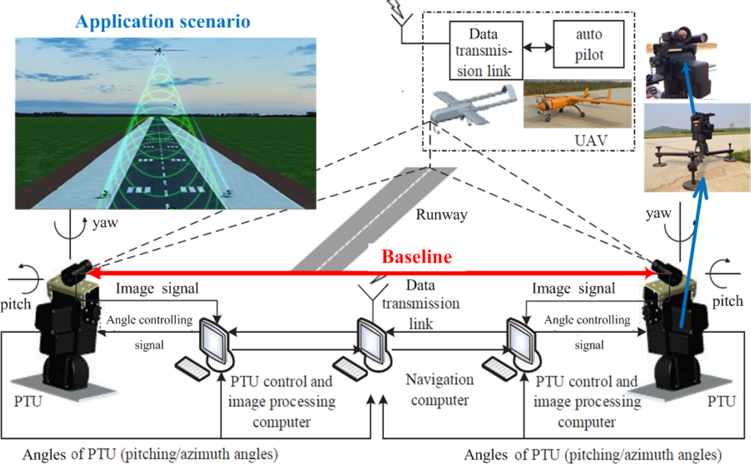
Schematic diagram of the navigation system for UAV autonomous take-off and landing. An application scenario for this navigation system is presented in the top-left of the figure.
The ground stereo vision system involves several workflow steps, e.g. system calibration, image capture, target detection and localization, as shown in Figure 1. In this study, flying target detection and localization by using the captured sequential binocular images is emphasized. Tang et al. [10] initially employed the Chan-Vese model [16] into detecting the aircraft in images and then used triangulation to calculate the spatial coordinates. The experimental results were comparable with the corresponding differential GPS (DGPS) data in some sections. However, mismatching phenomena did exist within specified scenario, e.g., the aircraft flying out of field of view (FOV) of the cameras, and higher errors caused by automatic target detection. The real-time feature was unsatisfactory for practical applications since the average time consumption of the localization algorithm was about 157 ms, and the maximal even reached to be 212 ms.
Under such circumstances, this chapter concentrates on the above-mentioned problems, in terms of real-time capability, accuracy and robustness for the ground stereo vision system. The contributions can be stated as follows:
An active region-of-interest (ROI) scheme is fused into the Chan-Vese model-based detection to improve the real-time feature of the proposed method. The present ROI is automatically generated according to predicted target position and size.
A robust spatial localization method is developed by fusing Extended Kalman Filter (EKF) [17] into state estimation to reduce the localization inaccuracy caused by measurement errors of object detection and PTU attitudes.
This remainder is organized as follows. Section 2 provides a brief review of related works. Problem formulation on UAV autonomous take-off and landing is presented in Section 3. In Section 4, aircraft detection and spatial localization algorithms are developed and implemented. The advantages of localization precision, real-time capability and robustness are verified by experiments in Section 5. Finally, Section 6 concludes the work done.
2. Related Works
The ground stereo vision navigation is developed for UAV autonomous take-off and landing within GNSS-denied environments. Flying aircraft detection is emphasized since it is one kernel component of the ground vision system. To our best knowledge, both corner-based and skeleton-based algorithms were employed into the flying object detection on the ground captured sequential images. In this study, one of skeleton-based schemes are concerned, and active contour is applied into extracting skeletons or edges in the images.
2.1. Active contour object detection
Active contour, whose basic idea is evolving a curve according to a partial differential equation (PDE), is constructed to extract the contour of an object. Active contour was introduced by Kass et al. [18] to segment objects in images using dynamic curves. As developed in [19], the active contour is further divided into parametric active contour models and geometric active contour models. The parametric active contours [18, 20] are expressed as the parameterized curves and optimally evolve in a Lagrangian framework. They have been used extensively in many applications over the last decades. The geometric active contours, introduced by Caselles et al. [21] and Malladi et al. [22], are represented implicitly as level sets of a two-dimensional distance functions that evolve according to an Eulerian framework.
To our knowledge, the image segmentation has played an important role in many applications like object tracking, medical image analysis [23], etc. As a category of classical image segmentation methods, the active contour model, however, has some problems in energy minimization process (described in Section 4.1) including initialization, stopping functions design and anti-noise robustness. To overcome some of these difficulties, Ksantini et al. [24] proposed a new active contour model that completely eliminated the need of the re-initialization procedure. Moreover, a polarity-based stopping function was proposed to automatically end the curve evolution instead of the widely used gradient-based stopping function. More recently, a novel reaction-diffusion method for implicit active contours was developed, which outperforms other classical active contour methods on noisy image in work presented in [25].
Gradient Vector Flow (GVF) [20] is a modified Snake algorithm. It solves two key problems: the first is that Snakes cannot move toward objects that are too far away and the second is that the Snakes cannot move into boundary concavities or indentations (such as the top of the character U). Chan-Vese model proposed by Chan and Vese [16] is able to automatically detect all contours regardless of the location of the initial contour. In this chapter, it is employed and developed to detect the flying target. In Section 5, we will compare the Chan-Vese model with GVF and Snake in terms of the detection performances.
2.2. Vision-based autonomous landing
Unlike GNSS-based navigation system [26], vision-based navigator is designed to achieve a successful GNSS-denied flight. Considering solving the landing problem, most researchers focus on onboard vision, such as a novel two-camera method for estimating the full six-degree-of-freedom pose of the helicopter in work by E. Altug et al. [27] and fixing a forward camera on a UAV to detect lines of target runway [28]. On the other hand, ground vision-based navigation systems have seldom considered for autonomous landing. In several ground vision-based navigation systems, Martinez et al. [29, 30] estimated the helicopter's position based on the detection and tracking of planar structures, but it relied on artificial markers. Another ground vision-based system used one CCD camera to recognize a square marker which size is already known and then measure the three-dimensional coordinates of the flight body, while the limited ranges of observation restricted the take-off and landing range [31].
3. Problem Formulation
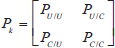
The ground stereo vision-based localization algorithm is to discern where the UAV object is during its autonomous take-off and landing process. Digital images and camera attitudes are the input of this algorithm and the real-time UAV position is the output. The whole algorithm is composed of two sections: Chan-Vese model-based object detection and EKF-based object localization. Object detection operator

where I is digital image domain, Pos
I
denotes target position in image (unit: pixel), and Pos
S
denotes target spatial position (unit: meter). As shown in Figure 2, the object detection operator

System architecture and workflow of the ground stereo vision system for UAV autonomous take-off and landing
3.1. Chan-Vese model-based object detection operator
Compared with the previous work [10], this chapter mainly improves the Initialization module for better performances on real-time capability. In previous work, we modeled the trajectory as a piecewise straight line. The estimated spatial position

It is assumed that the target trajectory is with continuous first-order derivative, which is more realistic than previous assumption of piecewise linearity of motion [10]. The trajectory

To realize smooth first-order differential of trajectory, modeling parametric curve piecewise is feasible. It is realized with recursion that is to say the trajectory is renewed by adding a new parametric curve circularly at each step. The detail will be discussed in Section 4.
In the present work,


where Tra
k
denotes the new parametric curve estimated in step k. The estimated spatial position is calculated by Tra
k
.
3.2. EKF-based spatial localization operator
With strong robustness, real-time capability and little memory cost, Kalman Filter (KF) [32] can estimate the system state by the measurement. The KF uses a series of measurements containing streams of noise and other inaccuracies to produces a more accurate estimation of unknown variables than those based on a single measurement alone. In other words, the KF operates recursively on streams of noisy input data to estimate a statistically optimal system state.
In this chapter, object spatial position and speed, PTU attitude and rotation velocity are modeled as the state

where all components are expressed in the global coordinate and they can be written as:


where lpan and ltilt denote left camera's yaw and pitch angle, and rpan and rtilt are the same to right camera. The wlpan, wltilt, wrpan and wrtilt are corresponding angular velocity.
The measurement z is modeled as follows:

where
4. Methodology
The whole localization algorithm is based on ground stereo vision system. The constant parameters are obtained by calibration, described in previous work [14], such as camera intrinsic and external parameters, PTU position and initial attitude, etc. Also, images captured from two cameras and PTUs attitude can be obtained in real time. With this information, extracting object using Chan-Vese model-based detection algorithm in image firstly and then locating the object with EKF-based spatial localization algorithm are done.
4.1. Chan-Vese model-based object detection algorithm
Chan-Vese model is a kind of geometry active contour model related with curve evolution theory and level set method introduced by Osher and Sethian for capturing moving fronts [33]. Level set method increases the problem's dimension to be higher. For example, a plane curve C is implicitly expressed as a same-value curve of three-dimensional continuous functional surface
The Chan-Vese detection algorithm aims at finding the target boundary by using an active contour approach. The active contour is dynamically evolved by minimizing the value of energy function F(C) with the level set method. As shown in Figure 3, an active contour is initially given and then it evaluates as the iteration of solving numerical partial differential equations. Finally, it will converge to the target boundary. The energy function F(C) in Chan-Vese model is as follows:
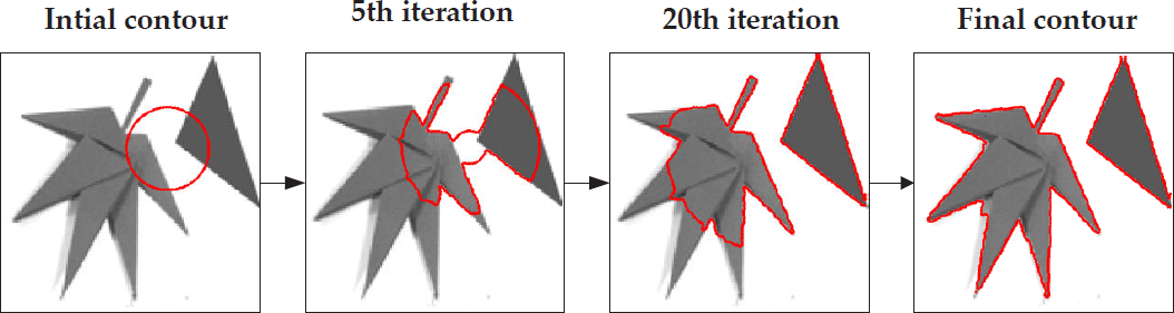
Chan-Vese model-based segmentation demo. The active contour (red contour) is initialized and finally becomes the object boundary through the active contour evolution.

where C is the ranging closed curve, and u is the matrix of the image. μ and v are coefficients. c 1 and c2 are average pixel intensity values of inside and outside regions of the closed curve respectively. Therefore (u-c1)2 and (u-c2)2 can be treated as the pixel intensity values' variance matrixes of inside and outside regions. L(C) is the length of closed curve.
From the viewpoint of applications, the schematic workflow of Chan-Vese detection algorithm is shown in Figure 4. This standard Chan-Vese algorithm has been employed into the flying aircraft detection with higher time cost [10]. Eventually, a ROI Scheme (red rectangle) is fused into the Chan-Vese model-based detection to improve its real-time feature, because the Chan-Vese detection takes over about 84% of the total time cost for each frame. The present ROI is automatically generated according to predicted target position and size which is provided by Trajectory Estimator module. The present spatial position of target is estimated on the basis of predicted trajectory, and projecting this three-dimensional coordinate to the image plane. Moreover, a rectangle is chosen as the ROI in this study. The rectangle's center is the predicted target position in image, and its size depends on the size of target region in last frame with additional basic size. Afterwards, the flying aircraft detection is taken with the ROI rather the original image. The image size reduction contributes to real-time capability promotion then.
Schematic of Chan-Vese model-based object detection algorithm
The computation time is undoubtedly reduced by focusing on the smaller-scale ROI, but it should be ensured that the aircraft is within the ROI. The detection accuracy on the target becomes an important issue. Thereafter, a more rational and precise trajectory should be estimated. It was assumed that the target is of piecewise linearity of motion previously and estimated current target spatial position as (1). As mentioned in Section 3, the speed of target is smoothed according to (2) and the target is supposed to move along with the trajectory with smooth first-order differential. These assumptions regarding object motion are more practical, and that the use of these assumptions will improve position estimation accuracy.
Assuming that the target has been located before step k, and spatial positions are marked as
The points
The tangential direction is the same as the direction of
The parametric curve
where
Supposing that the target kept moving with a constant speed (possibly different direction) during step k−1 and k, one point is obtained on this parametric curve:

where
4.2. EKF-based object spatial localization algorithm
Spatial localization is the following step of flying aircraft detection. Tang et al. [10] pointed out that the localization precision is significantly affected by both target detection errors and PTU attitude errors. High detection errors occur when most of the aircraft body is flying out of the field of view. Typically, the localization error was up to be about 29.12 m in the worst occasion.
Under such circumstances, (EKF) is employed to estimation on the aircraft spatial coordinates and suppresses the measurement error influence to localization accuracy. In this study, the EKF is used to estimate detected target positions in images and binocular camera attitudes, and the state
4.2.1. EKF Prediction
Let us estimate the state at step k by the state at step k−1:

where F k is a state transition matrix. Object position and camera attitude are predicted as follows:

where
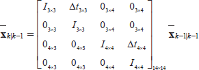
where

where Q
k
is covariance of the dynamic model with a zero-mean Gaussian noise, and G
k
is the Jacobian matrix of Q
k
with respect to the state
4.2.2. EKF measurement model
Equation (5) presents the measurement z, which is composed of three components:
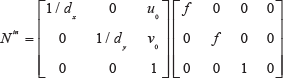
Pinhole camera model is used to project the estimated target position

The pinhole model of camera. P(x0,y0,z0) is the spatial point and p is the projection in image plane.
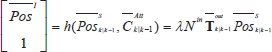
where λ is normalization coefficient.
where
Next, the measurement model is written as:
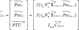
where J(⋅) outputs a new vector containing the first two components of the input vector.
In some cases, the estimated position is out of FOV, which implies that the target projection is not in the images. Thus, the untrusted detection results should be corrected. Intuitively understanding, the further the estimated target image position is away from image boundary, the smaller the probability is that the real target is within the image. A coefficient T is introduced to weigh the probability that the target is within the image, and the target image position (u k , v k ) is updated by T:

where
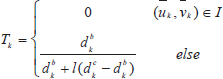
where I is digital image domain,
4.2.3. EKF correction model
The

The Kalman gain K k is:

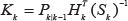
where R is Gaussian noise covariance matrix of the sensor for each measurement. Update state and covariance matrix:


Figure 6 shows the flow chart of the EKF-based localization operator
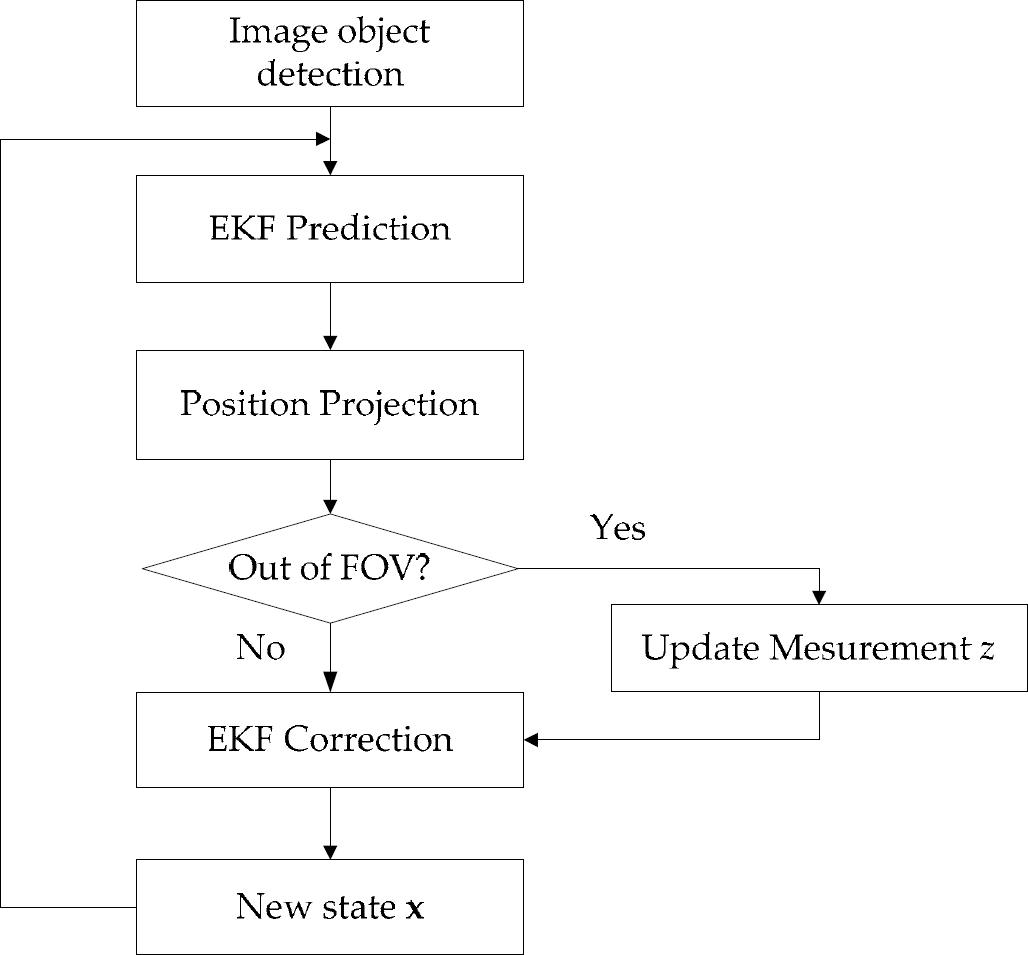
Flow chart of object localization operator
5. Experiments and Discussion
UAV autonomous take-off and landing system based on stereo vision is built for the experiments of this object localization algorithm [11–13]. As shown in Figure 1, the precise PTUs are set up on two sides of the runway, and the baseline is about 10.77 m. The visible light camera DFK 23G445 is set up on the PTU and turn along with PTU to extend field of view. At the same time, the high position resolution (0.00625 degree) and high rotatory speed (50 degree/sec) of PTU enables higher accuracy localization. Figure 1 also presents the aircraft for experiments, whose wingspan is approximately 2.3 m.
The proposed approach is to be validated by both offline and online experiments. The offline experimental data, including calibration parameters, videos, PTU attitude, and synchronous DGPS data, are obtained during autonomous take-off and landing guided by DGPS. As the product manual of DGPS lists, the localization error of DGPS is less than 2 cm 95% of the time. These experiments mainly verify four performances improvements compared with previous works and other state-of-the-arts:
First experiment confirms the better accuracy of Chan-Vese model-based object detection algorithm related to other active contours algorithms, such as snake and GVF snake.
Second experiment shows the real-time capability improvement of Chan-Vese model-based object detection algorithm.
Third experiment validates higher localization accuracy with EKF.
Final experiment shows better robustness to measurement error with EKF.
The center point of aircraft head is treated as target image coordinate in these experiments. Note that the online experiments are implemented during UAV autonomous take-off and landing, but the results are not offered to UAV as localization information for autonomous take-off and landing considering its safety. It should be noted that the algorithms groups we used in experiments are marked as follows:
CV_E denotes Chan-Vese model-based detection algorithm and EKF-based localization algorithm.
CV_T denotes Chan-Vese model-based detection algorithm and triangulation-based localization algorithm.
5.1. Object detection experiments
Object detection in image with high accuracy is the foundation to obtain highly accurate localization from stereo vision system. At the same time, real-time processing capability is the required key factor in task implementation.
5.1.1. Chan-Vese model-based detection accuracy experiments
To validate the high UAV detection accuracy using Chan-Vese model, we compared this Chan-Vese model-based object detection algorithm with Snake and GVF algorithms in terms of detection accuracy.
Figure 7 shows the segmentation procedures and results with Snake-based and Chan-Vese model-based algorithms respectively. The pre-processing is the histogram equalization result of S channel of HSV model. Experimental results show that the aircraft in image often topologically changes after the image pre-processing. The wing of UAV disconnects with main body after preprocessing (Figure 7). The segmentation result of Snake-based algorithm surrounded by red contour does not contain the wing because Snake is not adapted to topological change, which may lose integral target information and lead to detection error.

Comparison of Snake-based with Chan-Vese model-based region segmentation in terms of adaptability to topological change. The two right images are corresponding to the region surrounded by the yellow contour and they show the segmentation results encircled by the red contours with Snake and Chan-Vese algorithms, respectively.
One set of offline data collected from an autonomous landing are used to compare Snake algorithm and GVF with Chan-Vese model in terms of detection accuracy. The red, light blue and green trajectories in Figure 8 are generated by different detection algorithm but same localization algorithm (triangulation). Blue is generated by DGPS, and red and light blue are generated by GVF and Snake algorithm, and green is generated by Chan-Vese algorithm. When the UAV is closed to ground, which means that the background is most complex, the GVF and Snake algorithm-based localization errors increase. Images and localization results in points G and H are picked up and showed in Figure 9. It shows that the detection error is mainly caused by the wrong aircraft region segmentation because GVF and Snake algorithm can only segment one region. Chan-Vese algorithm segments several regions including the target region and picks up the right one through region filtering.

Localization results using different object detection algorithm. The blue trajectory is the reference trajectory generated by DGPS. The red, light blue and green trajectories are generated by GVF, Snake and Chan-Vese detection algorithm and triangulation-based localization algorithm. The Y global axis is along with the direction of the runway.

The detection results by GVF, Snake and Chan-Vese algorithms at G and H points in Figure 8(a)
5.1.2. Chan-Vese model-based detection real-time capability experiments
The real-time capability limit of the detection algorithm has been pointed out, which reaches about 157 ms every frame. The time consumption test consequence is that the Chan-Vese model-based region segmentation takes almost 84.1% of the total time required to process a frame of video. Hence, the reduction of region segmentation time consumption should be a most effctive way to promote real-time capability.
The real-time capability is tested in the same equipment in the previous work [10], which is a PC with 2.80 GHZ CPU and 6.00 GB RAM. Figure 10 indicates the reduction of segmentation time consumption with ROI setting. The time consumption decreases significantly as the ROI size reduces. However, the detection accuracy should not be ignored. Table 1 shows the detection average error at each image coordinate. With comprehensive consideration, 250*100 (250 is the width and 100 is the height) is the best basic ROI size, whose average errors are all below 1.00 pixel and average time consumption is about 20 ms. Most importantly, the time consumption of 250*100 in one video distributes relatively concentrative, which is a significant performance in real project.

Time consumption of segmentation with several sizes ROI in two videos. The values of X axis stands for the basic width and height of ROI. For example, 150 × 60 represents the width and height of the ROI (150 and 60 pixels) respectively. (a) shows an example of different size ROIs in an image.
Detection average deviation with different sizes of ROI related to the detection results without ROI setting

We compare the average time consumption of object segmentations with different algorithms, and these segmentations are with same initial conditions, iteration stop conditions and other conditions. The results are shown in Table 2. The Snake algorithm performs best but compared with Chan-Vese and GVF algorithms, Snake shows little advantage.
Average time consumption for object segmentation using three different algorithm: Chan-Vese, Snake and GVF algorithm

5.2. EKF-based localization experiments
Triangulation was used in previous work to locate the aircraft. Experiment results indicate that its localization accuracy and robustness are deeply affected by measurement accuracy including object detection and PTU attitude. To reduce the influence of measurement error effectively, EKF is introduced to estimate UAV position. Accuracy and robustness are improved in offline and online experiments.
5.2.1. Localization accuracy experiments
DGPS data are collected during autonomous landing process. These experiments treat them as the reference localization results. Two set of landing data are chosen to present the accuracy improvement with EKF. It should be noted that the UAV position and PTUs attitudes in EKF initial state are configured by DGPS and PTUs measurements because the UAV is located by DGPS before its autonomous landing.
The offline experiments discussed above are all about autonomous landing process, which is guided by DGPS for position and IMU for attitude. Figure 11 shows autonomous landing trajectories and localization errors in X, Y and Z directions. The blue trajectory is generated by DGPS, and the green and red ones are generated by CV_T and CV_E algorithms respectively. The three shadow areas denote three landing periods in which the image backgrounds are only sky, sky and ground and only ground, respectively. Table 3 indicates the root-mean-square error (RMSE) and improvement of each axis using EKF.

Two sets of offline experiments generating autonomous landing trajectory projections in XY and YZ planes and Localization errors in X, Y and Z directions. The three shadow areas denote three periods in which the image backgrounds are only sky, sky and ground and only ground respectively. The top image presents real ground environment captured by Google Earth.
The root-mean-square error (RMSE) and precision improvement with EKF at each axis. Only the trajectory (y>187 m) is used to calculate the RMSE in index 2.

There is a delay between images and DGPS for out-sync of data transmission, so it should be taken in consideration when the deviation is calculated. Assuming that the delay is constant and it is tested by experiments. The constant delay is set up to three image frames. In Figure 11(b), the deviation increases fleetly when the y coordinate is less than 187. That is caused by the weak DGPS signal when the aircraft is closed to ground. Through a set of electromagnetic environment test, the conclusion is that the electromagnetic environment is most complex in the region closed to the ground (less than 2 m), which leads to the weakest DGPS signal. When the DGPS signal is absent, the DGPS data are kept constant. Furthermore, big delays caused by continuous DGPS signal interruption are accumulated. That is why the deviation (y < 187 m) (Table 3) becomes bigger as image number increases.
In Table 3, EKF-based localization algorithm shows better accuracy especially in Z axis. Also, accuracy at X axis is improved obviously. And the deviation at Y axis is still about 2–3 m. The accuracy of height is most effective to real UAV autonomous landing. On the contrary, the accuracy in Y axis has minimal influence on its autonomous landing because of the long runway (about 400 m). The EKF-based localization algorithm reduces the deviation at Z axis for about 67.16% and 77.75%, which shows a significant improvement to autonomous landing. The limited width (15 m) of runway also needs a high localization accuracy at X axis. In conclusion, the localization accuracy improvement brought by EKF-based localization algorithm shows great significance to UAV autonomous landing.
In Table 3, RMSE of second experiment is calculated only from the trajectory whose y coordinate is bigger than 187 because of the incorrect DGPS data. Table 3 compares the errors in the X and Z directions, while the errors in Y direction (runway direction) are clearly higher. Figure 12 shows the localization errors caused by object detection errors (0-50 pixels) in u direction and v direction of image. Obviously, the detection errors cause significantly higher localization errors in y direction, because the baseline is much shorter than runway, and according to camera pinhole model (see Figure 5), an angle error will lead to higher localization error in runway direction.

Localization errors in X, Y and Z axis directions caused by different object image position errors. (a) The localization errors caused by equal errors in u and v directions. (b) Constant error in v direction and changeable error in u direction. (c) Constant error in u direction and changeable error in v direction.
5.2.2. Localization robustness experiments
When the predicted target image coordinates

The object detection and correction results in four special images respectively. (a) Detection and correction results in point A. (b) Detection and correction results in point B. (c) Detection and correction results in point C. (d) Detection and correction results in point D. These points are marked in Figure 11 (a). The projections of predicted UAV positions in the four images are out of FOV.
In Figure 11(b), the trajectory generated by CV_T in region M deviates the reference trajectory obviously. It is caused by object detection error. EKF-based localization algorithm is not so sensitive to measurement error for the use of historical information. Table 4 shows the localization RMSE in region M at each axis.
The RMSE and precision improvement with EKF of region M in Figure 11 (b)

The object detection error can be weighed by localization deviation with triangulation algorithm. The great promotion of localization accuracy at Z axis makes the impossible autonomous landing with 1.3028 m deviation to be realizable with 0.2111 m deviation. The results indicate the good robustness of EKF-based localization algorithm to measurement error.
5.3. Online localization experiments
The online localization experiments include an autonomous take-off and an autonomous landing. For the safety of UAV, it is still located by DGPS, and this localization algorithm is working in the ground station at the same time. The localization results are transmitted from ground computer to the UAV by the radio stations configured on ground and UAV. The transmission time delay is related to the transmission distance. We have tested the transmission delay and the results show that during autonomous landing it is about 30 ms. With additional images transmission and processing time consumption (about 80 ms), the total time delay is about 110 ms. According to the estimated UAV speed, we compensate for the final localization results assuming that the UAV is with constant speed during this time delay.
Figure 14 shows the localization results. The red trajectory is generated by this localization algorithm (CV_E) online, and the green trajectory is generated by CV_T algorithm with offline data for the accuracy comparison. The whole algorithm consumes about 100 ms of every frame. It means that the localization frequency is about 10 HZ which is available for real autonomous take-off and landing. Table 5 is the localization RMSE comparison of online experiments. The CV_E algorithm also performs better as offline experiments show. The RMSE at Y axis of take-off experiments reaches 15.1831 m, but it also meets the autonomous take-off demand owing to the long runway.

Online experiemnts results of a landing and take-off processes of a complete flight
RMSE and improvement with EKF at each axis of the online autonomous take-off and landing experiments

6. Conclusion
In this study, the ground stereo vision-based object aircraft detection and localization approach has been proposed and developed for autonomous take-off and landing of fixed-wing UAVs. The Chan-Vese model-based approach has been fused into flying object detection. An EKF estimator has been implemented to improve accuracy within scenarios, for instance, when the aircraft flies out of biocular views. By using the developed prototype of the ground stereo vision-based guidance system and the fixed-wing UAV, Pioneer, flying experiments have been conducted to collect sequential images and DGPS data. Both offline and online modes have been employed into performance evaluation of the spatial localization algorithms. The experimental results validate that the proposed approach effectively improves performances in localization accuracy, real-time capability and robustness.
Footnotes
7. Acknowledgements
This work was jointly supported by Major Application Basic Research Project of NUDT with Grant No. ZDYYJCYJ20140601 and the Scientific Research Foundation of Graduate School of NUDT. The authors would like to thank Boxin Zhao, Zhaowei Ma, Shulong Zhao, Zhiwei Zhong, Dou Hu and others for their contribution in building the ground stereo vision navigation system as our experimental platform.