
Abstract
To reduce the downtime and optimize the use of energy and manpower, a serial-parallel manipulator is designed for transferring heavy billets for a hot extrusion forging station. With the purpose of increasing the structural rigidity and restricting the end-effector (a gripper) so that it always moves in parallel with the ground surface, parallel links are added in between the serial links of the manipulator. This modification of the conventional structure must be considered in the modelling and analysis of the design. This paper addresses a methodology to investigate the kinematics performance and strength analysis of the designed robot. With respect to the parallel links, the constraint equation is derived and put together with the kinematical model. Based on the entire model that is formulated, the inverse kinematics, the transferring time, the reachable workspace, the degree of dexterity and the manipulability index are analysed and discussed to demonstrate its kinematical performance. In addition, to investigate the structural characteristics of the end-effector module, the static displacement and stress distributed on module's components are computed and simulated using the computer-aided finite element method (FEM). These research results are effective and useful in assessing and improving the robot's design.
1. Introduction
Today, hot extrusion forging is a major world-wide industry that has significantly contributed to the development of the manufacturing cycle. Forging is a manufacturing process involving the shaping of metal using localized compressive forces. In general, a hot forging station usually comprises a heating furnace and a forging machine which uses either a hydraulic press or a mechanical press for the billet extrusion. Consider a specific hot forging station, as described in the following Fig. 1.

Layout of the extrusion forging station
At the beginning of an extrusion forging cycle, workers grip a billet (weighing about 60kg) from the billet loading area (Position 1) and move and place it on the heating furnace (Position 2). When the temperature of the billet in the furnace reaches 1,100°C, the workers grip the billet again and transfer it to the die mounted on the forging machine (Position 3). After this, the forging operation begins to extrude the billet as required. The use of this billet-transferring method increases the downtime and fatigues the workers, since they handle hot and heavy billets. For this reason, an industrial manipulator needs to be designed for supporting the workers handling the billet. Fig. 2 shows the 3D design and Fig. 3 presents the schematic diagram of the robot.
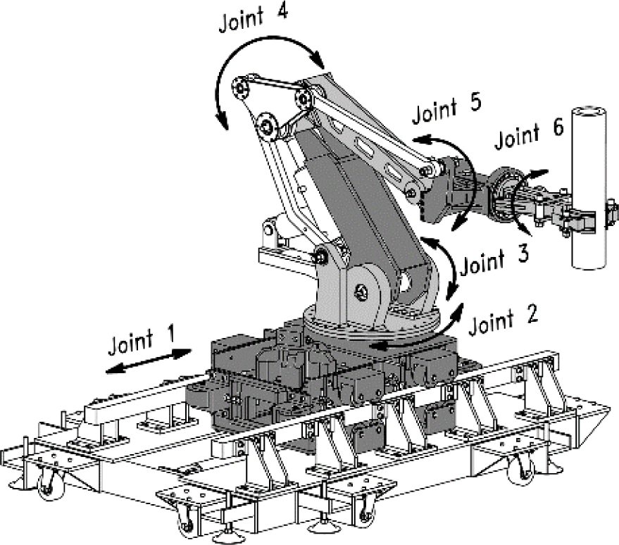
CAD model of the manipulator
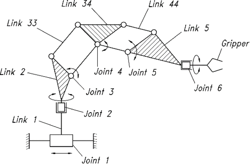
Schematic diagram of the manipulator
It consists of a fixed base and nine links jointed by kinematical joints with one degree of mobility. The prismatic Joint 1 and rotary Joints 3 and 4 are driven by hydraulic actuators. For every processing cycle, the designed manipulator is controlled to pick up a billet at Position 1 (Fig. 1) and transfer it to Position 2. After the heating process is completed, it continues picking up the billet, and moves and releases it at Position 3.
Notice that Links 33, 34 and 44 are added in order to close two local kinematics chains. This addition is necessary to increase the structural rigidity of the manipulator and to restrict the orientation of the end-effector (Link 6). In every configuration, the end-effector moves in parallel with the horizontal ground surface so that the robot grips and releases the billet in a more efficient and easy manner. This reduces the complexity of the positioning and control issues. Moreover, the addition of parallel links to the design reduces the number of joints variables; the displacement of Joint 5 depends on the displacement of Joints 3 and 4. This specification leads to a reduction of the number of actuators and simplifies the structure of the control system. Although the proposed design exhibits the advantages mentioned, it is more complex to model and control. For the design and control the robot, kinematics modelling and kinematics performance analysis play a central role and need to be considered specifically. In particular, the mechanical constraint arising due to the modification of the conventional structure of the kinematics chain must be considered in the modelling and analysis. The workspace, the degree of dexterity and the transferring time also need to be analysed in order to show the working capability and flexibility of the robot. The ratio of the lengths of Links 3 and 4 should be considered as well since it has an influence on both the manipulability and the stability of the system. In addition, the static deflection of the end-effector and the stress and the displacement distribution on the end-effector should be taken into account because the manipulator is subject to a heavy payload.
The kinematics of general serial manipulators have marked the fundamental problem. Further studies in this area can be found in the literature, such as the kinematics design of manipulators [1], the kinematics of the redundant robot [2], the kinematics of the parallel robot [3, 4]. There is much research in the area of the modelling and design of serial manipulators carrying heavy payloads [5–8]. However, there has been little research interest in the modelling and analysis of hybrid serial-parallel robot structures. In the area of study of the elastic deformation of the robot structure, the related research mostly focuses on the mathematical modelling of displacement and the control of flexible robots [11, 12]. Paper [11] proposes a systematic approach to assess the accuracy of a parallel kinematics machine subject to structural errors as well as how to effectively compensate for them. Analytical models were constructed for both the nominal and actual structures. A literature review of the state-of-the-art of flexible manipulators [12] reveals that the dynamic analysis and the control of flexible manipulators comprise an emerging area of research in the field of manufacturing, automation and robotics due to a wide spectrum of applications, ranging from simple pick-and-place operations of industrial robots to micro-surgery, the maintenance of nuclear plants and space robotics. Using a computer-aided finite element approach, the research presented in [9, 10] considers the analysis of the stress and displacement distributed on links designed with a given geometry and material. However, the analysis models in [9, 10] need more detailed calculation of the applied torques and forces for links, requiring strength analysis specifically. Fitting the entire design model of a complex manipulator into finite element calculation and simulation would generate complexity in analysing alternatives.
This paper presents the kinematics modelling of a serial-parallel manipulator designed for handling materials for a given hot-forging extrusion station. The numerical method is employed to analyse the forward and inverse kinematics behaviour of the system. The kinematics performance of the design is investigated and discussed. Finally, the maximum static deflection and the stress distribution on the end-effector are computed using the computer-aided finite element method (FEM). The presented methodology could be effective and useful in assessing and improving the robot design as well as in checking the strength and loading capacity of similar manipulators designated to handle heavy billets.
2. Kinematics Modelling
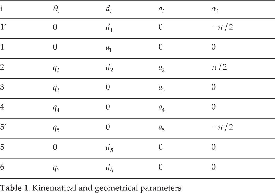
In Fig. 4, we denote q = [d1 q2 q3 q4 q5 q6]T as the vector of the joints variables. O0≡(O0x0y0z0) is the reference frame and O1, O2, …, and O6 denote the link frames. The coordinate systems 1′ and 5′ are added to create all the homogeneous transformation matrixes of the whole system according to the formulation of Denavit-Hartenberg,

Kinematical model
The matrix
Kinematical and geometrical parameters
In the reference frame, the homogeneous transformation matrix of the end-effector can be written as
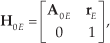
where
Multiplying all the transformation matrices yields

Substituting the parameters in Tab. 1 into Eq. (2) yields

Therefore,

Eq. (3) describes the forwards kinematics relationship of the robot. If we denote by

Due to the motion feature of the two parallel links, for every configuration of the system the relative positions of the frames O2, O3 and O4 are shown in Fig. 5. Based on this special geometrical relationship, the constraint equation for the motion of the system can be written as

The relationship between q3, q4 and q5

Eq. (5) shows that the joint variable q5 is dependent. Therefore, Eq. (4) has only five independent variables. Physically, Joint 5 is passive - no actuator is required for driving the joint.
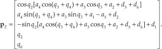
Substituting Eq. (1) into (5) and solving for p E yields
3. Inverse Kinematics and Kinematics Performance Analysis
3.1 Inverse Kinematics Analysis
To maintain the temperature of the heated billet during the transfer, the robot must move sufficiently quickly so that the transfer time is not greater than 22 s. In order to analyse the time of transfer and determine the joints variables according to the task in hand, the inverse kinematics model needs to be analysed.
Based on Eq. (6), the inverse kinematics problem is formulated as

Given


where A = a2 + d5 + d6, B = a1 -a5 + d2, a=- (yE - B)2+, (a4cosq4 + a3)2 and b = 2a4sinq4[a4cosq4 + a3)c = − (yE - B)2 + a42sin2q4.
Eqs.(8)–(12) show that for any point p E =[xE yE zE γ β]T given in the workspace, we can determine the value of q analytically. It is noticeable that this inverse computation is independent of time. For real-time control programming, the time-varying history of the joints variables q(t) must be determined according to the required end-effector trajectory, p E (t), represented in the time domain. In order to compute q(t), the time-varying path p E (t) must be planned. The planning procedure can be summarized as follows.
Based on the control points
Based on the required velocity profile ṡ(t) of the end-effector along the path, the arc length s(f) is also calculated as
Based on the numerical computation of s(t) and s(u), the time-varying parameter u(t) is determined by some numerical interpolation such as the function spline available in MATLAB: u(ti) = spline[s(ti), ti, s(ui)].
Substituting {u(ti)} into p E (u) yields p E (t).
Consider the design of the robot. The geometric parameters of the links are given as a1 = 0.11m, d2 = 0.25m, a2 = 0.1m, a3 = 0.73m, a4 = 0.63m, a5 = 0.18m, d5 = 0.03m, and d6 = 0.43m Suppose that ṡ(t) = 0.15m / sec is the velocity of the end-effector in a steady motion state. The parametric curve representing the required path, p
E
(u), is planned on the selected control points as
By using the presented procedure, the required curve p E (t) = [xE(t) yE(t) zE(t) γ(t) β(t)]T is obtained. Based on the input p E (t), the outputs d1 (t), q2(t), q3(t), q4(t), and q6(t) are calculated by implementing Eqs. (8)–(12). Fig. 8 shows such a numerical solution to the inverse kinematics equation of the robot.

Time history of the joints variables
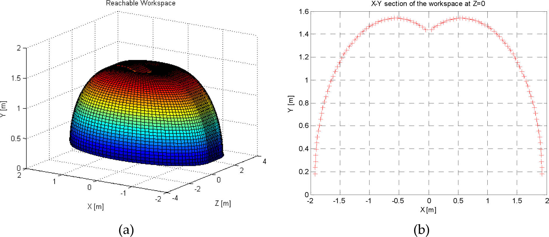
The reachable workspace: a) 3D boundary surface and b) x-y section at z=0

The manipulability index versus q2 and q4
The shape of the curves and the values of the points on the curves depend on the task required of the end-effector (the control points of the path and the velocity along the path). In the case of transferring billets for the forging process, none of the joints variables change outside the feasible range. By using this analysis technique for any given task assigned to the designed robot, the operation of the robot can be demonstrated and the feasibility of the joints variables' variations can be checked as well. It is essential for the robot's program to control the end-effector so that it moves at the required velocity along the desired trajectory, passing all the control points selected in the workspace. It is also important that the inverse kinematics analysis also displays the time required for the transfer task. At a given velocity ṡ(t) = 0.15m / sec, the transfer time is 15 s.
3.2 Reachable Workspace Analysis
The reachable workspace of the Robot,
3.3 Dexterity Analysis
The tendency of any changes in the dexterity characteristics along with the variance of q is of importance and should be analysed for the design. In particular, the kinematics manipulability index

As seen in Eq. (13), the value of the manipulability index only depends on the value of the variables q2 and q4 rather than on the other variables d1, q3 and q6. Fig. 8 shows the variation of the manipulability index along with q2 and q4. The robot will operate at maximum dexterity (ω → max) if q2 = 0 and q4 = − π / 2. In order to maintain the dexterity level, the “green” region where q2→ ± π / 2 and q4 → 0 should not be selected as the range of rotation of Joint 2 and Joint 4. In addition, Eq. (13) also shows that the manipulability index depends on the geometric parameters a3 and a4.
Fig. 9 illustrates the variance of the index value along with the ratio of the lengths of Links 4 and 3, ka = a4/ a3, in the case where a3 + a4= const and q2 are given. Both the dexterity and the geometric parameters of the manipulator are influenced by the value of ka. If ka increases, the index ω will increase but the stability margin of the system may decrease since the horizontal distance from the centre of gravity of Link 4 to O′1 and the link's mass and inertia increases. In contrast, if a smaller ka is chosen, the lower limitation of the range of q4 should be extended to maintain the dexterity of the robot. Therefore, the manipulability and stability must be taken into consideration simultaneously by selecting a proper value for ka. For the case of the robot, to allow a trade-off between dexterity and stability, the lengths of Links 3 and 4 are chosen as a3 = 0.73m and a4 = 0.63m; the lower limitation of q4 is checked with q4min= − 1.971rad.
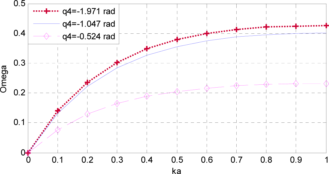
The manipulability index versus ka = a1/a3
4. Analysis of the Stress and Displacement Distribution on the End-effector
Structural analysis is a key part of the design of the robot. For a simple manipulator, the stress and displacement fields distributed on the components could be determined analytically to check the strength of the designed links. However, for complex structures, the use of robust computational techniques leads to better efficiency and accuracy. As for the manipulator, the end-effector's deformation and stress contribution need to be investigated because the cross-section of the griper geometry is smallest, as compared with the cross-sections of Links 3 and 4; the manipulator grips directly onto the heavy billet. Moreover, Links 3 and 4 are actuated by strong hydraulic cylinders.
In this section, the static stress and displacement distribution on the end-effector module are computed and simulated using the FEM integrated in the CAE software Autodesk Inventor (ANSYS Mechanical). Consequently, the maximum value of the stress and the deflection of the end-effector are determined in order to examine the safety factor and the loading capability of the robot.
Fig. 10 presents the 3D model of the end-effector module as acted on by the external forces P b = 589 N (the billet gravity), Rc = 981 N (the force that the billet reacts to the griper), P e = 677 N (the end-effector gravity) and Ra (the force that the ball-bearing transmits to the structure).

Structural analysis model of the end-effector module
To determine the unknown reaction force Ra, the following structural model in Fig. 11 is considered.
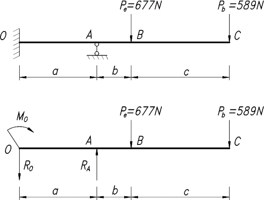
Simplified model to determine Ra
We denote by y1(z), y2(z) and y3(z) the displacements along the segments OA (a = 256mm), AB (b = 99mm) and BC (c = 340mm), respectively. Notice that the constant EJ characterizes the elastic property of the material. Solving Eqs. (14)–(18), in which Eqs. (16)–(18) represent the continuous vertical displacement of the end-effector, yields R0 = 277 N, Ra = 1563 N, and M0= 23637 N.mm.


Assigning all the obtained values of the moments and forces and running the analysis model on ANSYS, the distribution of the stress, the safety factor and the displacement are simulated, as shown in Figs. 12, 13 and 14, respectively.
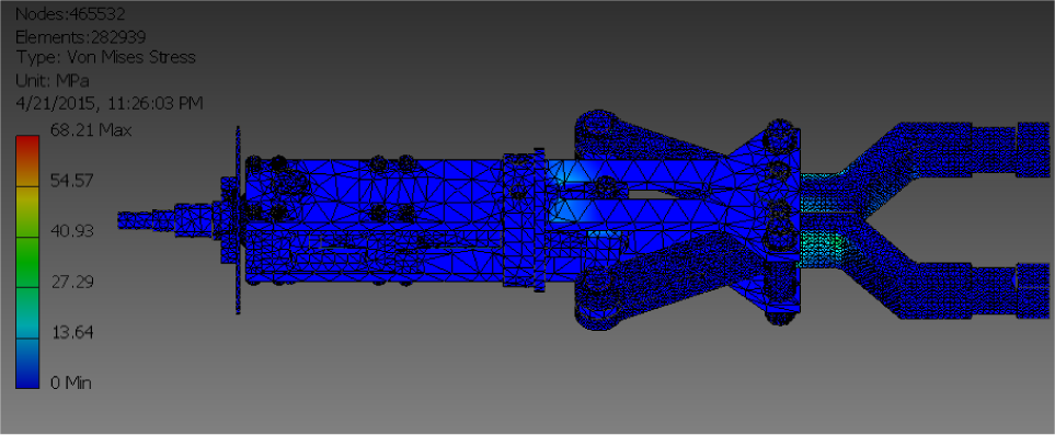
The stress distribution

The safety factor of the module
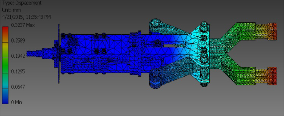
The displacement of the module
As depicted in Fig. 12, the maximum stress is 68.21 MPa, which is much lower than the yield strength of the designated material, σ = 99 MPa. Fig. 13 shows that the minimum safety factor is 3.85, which is greater than 2.73 (the allowed safety factor). These results show the loading capacity of the designed end-effector with respect to its material and geometry. As seen in Fig. 14, the maximum value of the displacement is 0.3237 mm. This is also meaningful as regards constructing the control algorithm and the program. The programmer should consider and compensate for this value inside the controller so as to increase the accuracy of the robot gripper.
5. Conclusions
In this paper, the design of a serial-parallel robotic system for handling billets for a given hot-forging extrusion station was analysed based on the kinematical and structural models. The kinematics modelling and analysis validate the kinematics chain that was designed. By considering the parallel links, the kinematics constraints equation is written and put together with the kinematical model. This method reduces the number of joints variables and restricts the orientation of the end-effector as desired. These features thus reduce the complexity of the robot control program -the robot grips and releases a billet in an efficient and simple manner. The inverse kinematics analysis shows that the manipulator needs only 15 s to transfer a hot billet from the heating furnace to the forging die, provided that the velocity of the end-effector is 0.15m / s. The workspace and the dexterity analysis prove that the manipulator is capable of working flexibly. Within the active range of the joints variables, the manipulability index analysis reveals that no kinematical singularity arises while the robot is operating. Besides, the dexterity analysis could be useful in selecting the proper ratio of the lengths of Links 3 and 4. Finally, by using the FEM integrated in the CAE software, the static stress and displacement distributed on the end-effector are analysed. The maximum value of the equivalent stress and the static deflection of the end-effector are computed to predict the strength, the safety factor and the loading capability of the robot.