
Abstract
In order to simulate the swing conditions of a suspended platform of a construction shaft, marine ships, cars, etc., an incompletely restrained cable-suspension swing system driven by two cables (IRCSWs2) was designed and parameter trajectories of displacements, angles and tensions were systematically investigated. Firstly, the motion mechanism of the IRCSWs2 is described and the corresponding kinematic model is established. For further evaluating the analytical expressions, the ADAMS simulation model and the physical prototype experimental model were developed. The basic consistency and slight difference among the three models are illustrated by a comparison of different parameters. The approximately linear relationship between the driving displacements of two cables and the swing angles of the platform was obtained. Finally, the effects of various parameters on displacements, angles and tensions were analysed, and the results indicate that the translation of a suspended platform is slight during its swing and that the novel IRCSWs2 can be used to drive heavy loads using a relatively small driving force, which is useful for simulating swing environmental conditions long-term, in addition to being cost-effective.
Keywords
1. Introduction
Swing conditions often occur on many transport platforms such as sinking platforms in the mining industry, marine ships when sailing, etc. In order to improve the reliability of equipment in these swing conditions, swing platforms are often designed for testing the behaviours of equipment. Generally, there are two alternative methods for controlling the posture of the platform: traditional rigid suspension driven manipulators [1] and cable-driven parallel manipulators (CDPMs) [2–4]. The CDPMs have several advantages over traditional rigid suspension driven manipulators through the use of cables instead of rigid links, delivering a larger workspace [5], complex environment adaptability [6], smaller power consumption [7] and high payload-to-weight ratio [8]. However, CDPMs with a high degree of coupling is relatively complex and the trajectory of a moving platform is primarily restricted by its requirements [9]. Therefore, its control procedures are more challenging in the case of all cables and there is both positive and limited tension. According to these challenges, comprehensive research has been conducted on CDPMs in terms of type synthesis [10, 11], kinematics and dynamics [12, 13], workspace analysis [3, 14, 15], error analysis [16, 17], etc. For example, based on an interval analysis, approaches to the wrench-feasible workspace determination of completely restrained CDPMs have been proposed, which is capable of dealing with small uncertainties regarding the geometric design parameters of CDPMs. However, it is very difficult for redundant CDPMs to avoid cable interference. Incompletely restrained CDPMs cannot control all DOFs; instead, external force is applied to maintain all cable tension [18, 19].
In this paper, based the research findings noted above, a novel design of an incompletely restrained cable-suspension swing system driven by two cables (IRCSWs2) was developed. A gantry crane, where a load is suspended from a single cable, has been used in engineering applications for decades. A cable in this type of mechanical system is suitable for lifting a heavy load such as a sluice gate and container in at least one or two directions of translation [20, 21]. Trajectory planning in underactuated systems is a challenging task. Consequently, motion prediction requires very good models of sway motion with sophisticated sensor technology [22]. It is generally known that a gantry crane is a typically underactuated mechanism similar to IRCSW2. In this paper, the motion mechanism of the IRCSWs2 is described and the corresponding kinematic model is established. For further evaluating the analytical expressions, the ADAMS simulation model and the physical prototype experimental model were developed. The suspended platform is driven by two cables that are underactuated and it uses external force to maintain all cables in tension. The purpose of this is to discover the performance of the suspended platform in its trajectory and the possible payload applied on it. A simple analytical model without accounting for dynamics is necessary in the conceptual design of cable robots. Finally, the effects of various parameters on displacement, angles and tensions were analysed. Time-varying inertial effects were not involved in the cable model, which focuses instead on the kinematics of quasi-static trajectory behaviour. In order to investigate the trajectory characteristics, the following assumptions were considered:
The density, cross section area and properties of each cable were supposed as constant.
The cable is supposed to form a straight line.
The effects of bending stiffness, friction and damping are negligible.
Swing motion is very slow and dynamic effects are negligible.
The interaction of both actuators simultaneously working has a negligible impact on performance.
2. Mechanism of IRCSWs2
In order to control the posture of the suspended platform, two independent cables were adopted instead of four; each cable formed a closed-loop mechanism by connecting two suspended platform joints, as shown in Fig. 1(a). A schematic view of the IRCSWs2 is shown in Fig. 1(b).

A simple schematic of the IRCSWs2
Using the schematic, the 3D model of the novel IRCSWs2 was designed and is shown in Fig.2. The IRCSWs2 is composed of two cables, pulleys, actuators, a base frame and suspended platform. Four connecting joints are symmetrically distributed around the suspended platform. Each cable is driven by an actuator in the middle of each cable and it can be driven back and forth using periodic motion.

3D model of the IRCSWs2
3. Kinematic model of IRCSWs2
3.1 Geometric equation
Ob - XYZ and O - xyz denote two frames assigned to the base frame and suspended platform, respectively (Fig.3). The tangential point between the suspended cable and the first pulley is denoted as Ui and the joint is denoted as Di. The position and orientation O - xyz with respect to Ob - XYZ is defined by the configuration vector q = [pT, θT]T, in which p = [x, y, z]T is the position vector and θ = [α, β, γ]T is a vector representing the orientation of O-xyz with respect to Ob - XYZ using Euler angles.

Schematic diagram of IRCSs2
Fig.1 shows each cable with its corresponding pulleys; the cable actuator constitutes a swing motion around an axis of the local coordination system. The suspended platform will have swing motion around the Y axis if cable 1 is driven by one actuator; it will also have swing motion around the X axis if cable 2 is driven by another actuator. The composite motion is designed and implemented in the task space coordinates when cables 1 and 2 are driven together. The system is equal to the suspended platform hang with four suspended cables.
The suspended platform appeared to have a dissymmetrical structure, which will contribute to mass centre position. The coordinate for the mass centre of the suspended platform is O' =(k1, k2, h) in which k1, k2 and h represent eccentric distance. Each suspended cable of the IRCSWs2 can be divided into two parts: the suspended portion lsi and the horizontal portion lhi. The lsi ranges from Di to Ui and the rest of the suspended cable is denoted as the horizontal portion. While only cable 1 is driven, the posture of the suspended platform can be simplified as shown in Fig.4, where L is the length of the suspended platform, M is the mass of the suspended platform, g is gravity acceleration and ϕ and φ are the angle between the base frame and suspended portion.

Cable 1 working alone
The swing motion of the suspended platform can be formulated by Eq. (1).

where,
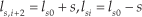
in which ls0 and s represent the length of the suspended portion of the initial conditions and amplitude of driven displacement, respectively.
3.2 Kinematic model
Based on the motion mechanism of IRCSWs2, the equilibrium equation of the kinematic model for the suspended platform can be written as

where τ is a four-dimensional vector of cable tensions and J represents the Jacobi matrix, defined as

This paper focuses on kinematics analysis without the effect of inertia force. Then, the term

The unit vector along the suspended portion of the ith suspended cable is denoted as di which can be written as
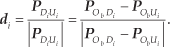
The position vectors will be defined with respect to Ob - XYZ, for example, PODi is the position vector described in Fig.5.

Schematic vector of cable
According to Fig.5, the PODi is expressed as

where

where c(·) and s(·) denotes shorthand writings for sin() and cos() functions, respectively.
Furthermore, the geometric matching conditions at the interface between the suspension cable and the suspended platform can be expressed as follows:

in which ρ, E, A, τ i , l' si and li represent the density, Young's modulus, the section area, the tension of the cable, the length of the suspended portion after elongation and the full length of the suspended cable, respectively.
3.3 Solution
Least squares solutions are determined by the systems of nonlinear equations, which are composed of Eq.(2) and Eq. (7). The systems of nonlinear equations have 10 nonlinear functions. Then, the maximum driven displacement is resolved by referring to the maximum swing angle. Based on Eq.(1), the boundaries of posture and tension are defined as the range of estimated parameter Ω, which refers to a given maximum swing angle, the mass of the suspended platform and other system parameters.

where the arguments
The flowchart of the algorithm for the numerical solution is shown in Fig.6. The algorithm was created using the optimization toolbox in Matlab using a trust-region-dogleg algorithm; initial values should be provided. It is highly recommended that the ‘fsolve’ command be employed. Matlab's built-in fsolve function is based on nonlinear least-squares algorithms and attempts to solve systems of equations by minimizing the sum of the squares of components. The roots of the equations are the least-square solutions on its estimation range.

Flowchart of the algorithm
The default trust-region-dogleg method [23] can only be used when the system of equations is square, i.e., the number of equations equals the number of unknown variables. The number of components of vector x is made up of six posture variable unknowns and four cable tension unknowns.
“Node H taking the initial I” is intended to allocate dynamic memory, which provides a convenience to the program. Node H is a two-dimensional array that stores solutions; the symbol I is zero, whose size is the same as Node H; “randroots” is intended to create a vector with the same length as x and random values in the range of the estimated parameter. When the trust region radius is less than a certain value, the procedure will run again using different initial values. Different random initial values are of the same convergence rate. The solution that final solution at the end of a successful step is used at the initial function value at the following step may decrease the number of iterative search steps.
4. ADAMS simulation and experiment models
4.1 ADAMS simulation model
In order to verify the theoretical model further, an ADAMS simulation was conducted, which is shown in Fig.7. For the dynamic response of models that move very slowly, time-varying effects were neglected and the results shown using software was similar to the kinematics solution. The key parameters involved in the static simulation of the IRCSWs2 are listed in Tab.1. Roots s of algebraic equation Eq.(1) was calculated by computer programming. The driven function is defined as 0.536 · sin(2πt / 10).
Parameters of ADAMS simulation


ADAMS simulation model
The interaction forces between two bodies were substituted by spring-dampers for the sake of simplification, as shown in Fig.8. The method and procedure of the ADAMS simulation model were applied by referring to the literature [24]. Field elements of the mathematical model were adopted, which contained a six-by-six matrix of the stiffness coefficients and the damping coefficients. In addition, the contact force between cable and pulley was defined using Hertzian contact theory. The two cables were discretized into 719 rigid cylinders and each cylinder was defined as being 20cm long and with a weight of 0.1940 kg.

Schematic of the relationship between cylinders and pulley
The process of the ADAMS model is described as follows: firstly, a set of rigid cylinders was defined as located on the tracks of the suspension cable. Fig.8 shows the relationship when the rigid cylinders wound around the pulley. Secondly, adjacent rigid cylinders were connected by the field force and the contact force was specified between rigid cylinder and pulley. The parameters of the field force and the contact force are shown in Tab.2. Thirdly, the end of each cable was connected to the suspended platform by a spherical joint and two translational joints were created at the middle of each cable. Displacement motions were specified at corresponding translational joints. The relationship between adjacent rigid cylinders can be analytically expressed as follows:
Parameters of the ADAMS simulation

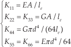
where, le represents the length of a rigid cylinder. Tab.1 and Tab.2 explain the meaning of some symbols adopted in Eq. (8). The values of the tension and the posture of the suspended platform are also given.
4.2 Experimental models
In the laboratory, a prototype of the IRCSWs2 was built for conducting experimental tests (Fig.9) and the parameters are given in Tab.3. The prototype was a small modelling experiment, which was used to verify the theoretical analysis of the IRCSWs2. Two linear motions, which are applied at the middle of each cable, were used to control the swing motions of the suspended platform of the prototype. The IRCSWs2's performances were obtained by an inclinometer, which was installed at the centre of the suspended platform. A wireless receiving module was adopted for receiving data from the inclinometer.
Parameters of the prototype model

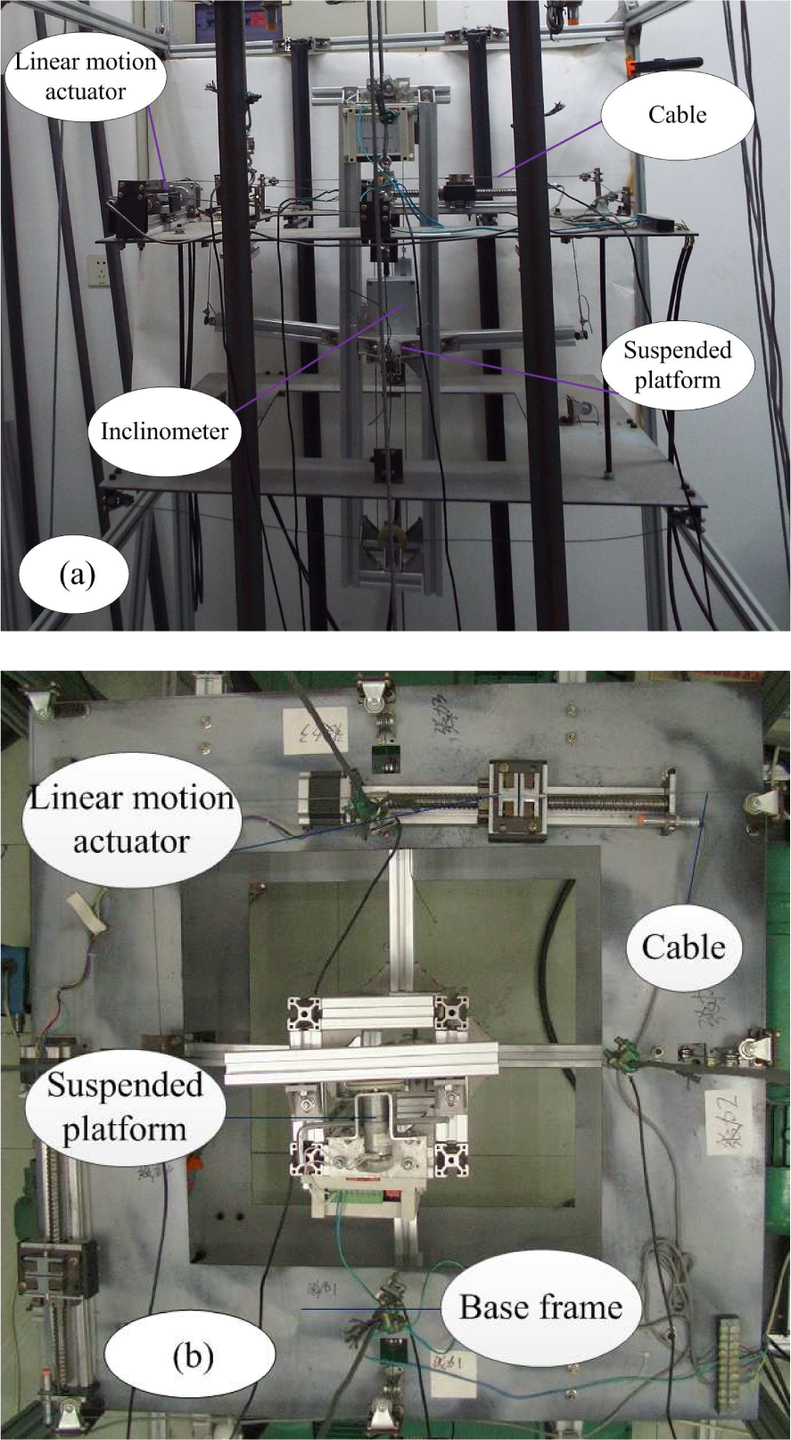
Prototype of the IRCSWs2: (a) Front view; (b) Top view
4.3 Comparison among theoretical solutions, ADAMS simulation and experiments
Rotation around the front-to-back axis (Y axis) and the side-to-side axis (X axis) of the suspended platform are shown in Fig.10. The consequences of the suspended platform swings around the X-axis, Y-axis and Z-axis, and its translations along the X-direction, Y-direction and Z-direction are presented in Fig.11, respectively. Fig.11(a) and (b) show that the suspended platform swings around the X axis and Y axis according to the desired swing angle. Furthermore, rotation around the Z-direction is small. The results from Fig.11 (d), (e) and (f) indicate that the cable actuator applied to each cable will cause small translations of the platform along different directions. Therefore, the translation effect on the instrument might be negligible. For example, the maximum translation is not more than 0.025m. The absolute value of the Z-coordinate is less than 1.77m, which indicates that two cables have tension at all times.

Swing motion results

Angles and displacements for the ADAMS simulation and theoretical solution
Comparisons of tensions between the ADAMS simulation and theoretical solution are given in Fig.11. Amplitude variation for each cable tension was relatively small, indicating that the IRCSWs2 has the advantage of a small driven force and easy realization of the swinging angle.
Swing angles about the X-axis, Y-axis and Z-axis of the suspended platform, measured by the inclinometer in the experiment, are shown in Fig.13, where experimental test results, theoretical calculation results and ADAMS simulation are, respectively, denoted by black lines, red lines and blue lines.

Cable tensions for the ADAMS simulation and theoretical solution
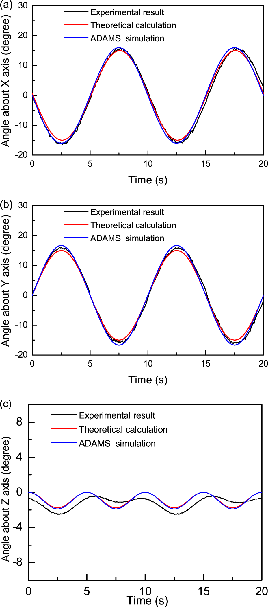
Comparison of attitudes among three models
The results from Fig.11 −13 indicate that the theoretical solutions were in a reasonably good agreement with the ADAMS simulation and experimental test. However, there were some small differences among the results, which may primarily have resulted from the following factors: (I) each rigid cylinder made contact with the pulley by contact force leading to small fluctuations in cable tension in the ADAMS simulation; (II) the noise and vibration of the linear motion actuator at low speeds in experimental test led to differences; (III) the geometric centre and mass centre of the suspended platform showed minor mismatches; (IV) there was some difference in cable Young's modulus of experimental test and theoretical calculation, and the effect of micro-acceleration was not taken into consideration.
The rigid cylinder technique, which satisfies cable properties such as consistency and elasticity, is based on the notion of the discrete method when describing system models. Compared to FEM techniques, it is easy to numerically simulate millions of particles on a single processor when adopting this method and changes in the suspended portion can be calculated simultaneously.
The ADAMS model is different than the theoretical model, especially in terms of cable representation. In order to evaluate the computational efficiency of computing time, both models were tested and the results showed that the computation time of the theoretical model with the time step Δt = 0.1s was within six minutes on an Intel®Core(TM) i7-3770, 3.9 GHz CPU processor. The theoretical model needed very little computation time, whereas the ADAMS model introduced in this paper was extremely time-consuming. The entire model required at least 33 minutes of computation on ADAMS 2010, because the penetration depth tended to be larger due to integration errors and more contact points being detected. The computation time for the ADAMS model and the theoretical model varied widely.
4.4 Impulse response
The finite impulse response models were directly estimated from the ADAMS model test data to gain a sufficiently accurate model for predictive control design and system sensitivity. An impulse of horizontal force signal is designed to predict system dynamic characteristic, and the pulse force amplitude is 1kN with a 5.04% platform weight. The response results are shown in Fig.15. If the response amplitude was of concern, it became clear that displacement along the X direction had a large amplitude that was close to 0.84s at its maximum. The amplitude decayed to nearly 87.69% after the first cycle and showed standard exponential decay. It took about 82 seconds for the impulse response of this system to reach a steady state. The results of the system's transient responses to impulse commands demonstrate that IRCSWs2 is sensitive to disturbances and that responses needed to be improved. The response of the output relative to the input indicated that the tension device needed to be taken into account to suppress lateral displacement.

Impulse response

Simple-axis swing and double-axis swing.
5. Effects of parameters on displacements, angles and tensions
Symmetry properties and small swing angle also contributed to lowering the coupling between rotation around the X axis and rotation around the Y axis. The difference between single-axis-swing and double-axis-swing is shown in Fig.15. Subscripts S and D represent single-axis-swing and double-axis-swing, respectively. The corresponding displacements in X, Y and Z directions are represented as dx, dy and dz. Similarly, the corresponding angles of X, Y and Z directions are represented as α, β and γ. Yaw angle γ has not been described, since it was small. Rotation around the X axis caused translation along the Y-direction by heading into an oppositional direction, as shown in Fig.15(a) and (c). Similarly, translation along the X-direction was caused by rotation around the Y axis. Small translation was caused by the double-axis-swing, slightly larger than the single-axis-swing, as shown in Fig.15(a) and (b). The amplitude of the double-axis-swing angle was almost consistent with single-axis-swing angle shown in Fig.15(c). Fig.15(b) shows displacement along the Z axis compared to differences between both actuators (simultaneously acting and simple acting actuators). The conclusion can therefore be reached that interaction of both actuators when simultaneously working has a negligible impact on performance and as such, confirms the assumption of this study's validity.
Fig.16(a) shows the approximately linear relationship between the driving displacements of two cables and the swing angles of the platform. The relation between the difference in tension in the same cable and the actuator displacement is presented in Fig.16(b). The graph shows that there is a periodic change in the same cable and that the amplitude of tension is no more than Mg / 50 over a given period of time.

Analysis of the IRCSWs2: (a) relation between displacement and swing angle; (b) driven force and actuator displacement
To illuminate the effect of the suspended portion length, the model was calculated by different suspended portion lengths. The value of driven displacement s slowly decreased as suspended portion length increased (see Tab. 4). Tracking displacements among different suspended portion lengths are shown in Fig. 17, where A, B, C, D and E represent different suspended portion lengths that are equal to 1m, 1.5m, 1.77m, 2m and 2.5m, respectively. Displacements along the X-direction, Y-direction and Z-direction are reduced alongside the length of the suspended portion increasing. The tensions among different suspended portion lengths are shown in Fig.18, which indicates that a long suspended portion length is useful for reducing the amplitude of displacement and tension.
The solution s of different suspended portion lengths


Tracking displacements among different suspended portion lengths
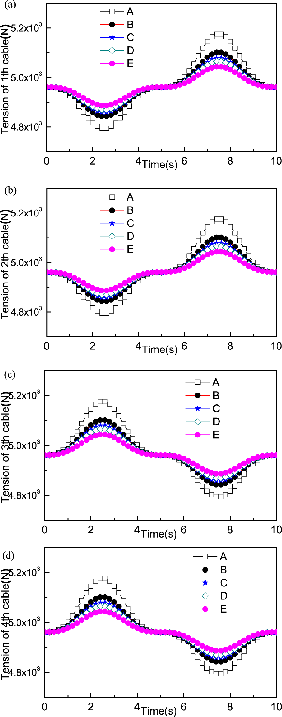
Cable tension among different suspended portion lengths
6. Conclusion
A incompletely restrained cable-suspension swing system driven by two cables (IRCSWs2) was designed. This novel structure is first and foremost put forward as a mechanism for the simulation of actual swing motions. The results of the IRCSW2 were as expected. An ADAMS simulation and experimental test models were established. The validity of the theoretical solution was verified by the two models presented above.
This algorithm included static mathematical models to avoid complex numerical procedures and to cope with forward static analysis problems. Approximately linear relationship between the driving displacements of two cables and the swing angles of the platform was obtained. The effects of parameters on displacements, angles and tensions were discussed. The results indicate that translation of the suspended platform was slight during its swing. An appropriate vertical length of cable is useful for reducing the amplitude of displacement and tension. Furthermore, the IRCSWs2 can be used to drive a heavy load by using a relatively small driven force, which is useful for simulating environmental swing conditions; the IRCSWs2 will also be useful in long-term work and will be cost-effective. The computation time between the ADAMS model and the theoretical model varied widely. By comparing both models, the IRCSW2 was shown to be very competitive in terms of computation time for trajectory analysis. The results of the system transient responses for the ADAMS model to impulse commands demonstrated that IRCSWs2 is sensitive to disturbances and that the tension device needs to be taken into account to suppress lateral displacement. For further study, a high-order continuum model was employed for conducting an effective and approximate dynamic response analysis of IRCSW2.
Footnotes
7. Acknowledgements
This research was sponsored by the National Natural Science Foundation of China (51475456), “Program for New Century Excellent Talents in University” (NCET-13-1017), “Program for Innovative Research Team in University” (IRT1292) and “a Project Funded by the Priority Academic Program Development of Jiangsu Higher Education Institutions ‘PAPD’”.