
Abstract
This article proposes a six-wheel lunar exploration robot which will move on the lunar surface. It is known that lunar surface is mostly rugged. When the six-wheel lunar exploration robot moves on the rugged surface, its centroid position will change, which has an impact on the vehicle obstacle performance and anti-overturning performance, and so on. Therefore, it is very important to analyze the centroid domain of the robot. In order to get the relation between centroid domain and position as well as the posture equation during the motion process, the kinematics model of the robot is built based on the coordinate transforming relations. So the calculation formula of centroid domain and body posture equation at any movement position are obtained. The mathematical model of detection robot is analyzed by entity analysis. So the centroid vector model of radial angle change curve and the changing rule of both sides of the rocker arm angle and centroid vector mode are given. MATLAB [version 6.0] is used to optimize the parameters of the robot and ADAMS is used to simulate the process when the robot moving on the rugged lunar surface. The results show that the centroid domain is a flat area. Based on the calculations and simulations, the vertical displacement and the pitch angle of the robot are decreased with different degrees after the optimization of the rocker arm suspension and the integrated moving stable performance of the lunar exploration robot is obviously enhanced.
Keywords
Introduction
Mobile robots have become increasingly present in human-related activities either to remove the hazards or to carry large and critical payloads safely. Mobile robot is capable of moving around in different environments including stairs and outdoor grounds. 1 Six-wheeled rocker arm hanging posture lunar exploration robot is a kind of mobile devices which is widely used in the field of planetary landing. Because the surface of most planets is uneven, the radial suspension frame structure can make the rover smoothly through the obstacles and keep as many as possible of the wheels contact with the ground, in order to prevent the rover could not move due to skidding or wheel hanging up. 2 Lunar exploration robot drives on the rough surface of the moon, its centroid position affects the tilting resistance and the obstacle-surmounting performance, so the determination of the centroid domain 3 and body posture 4 is very important to study lunar exploration robot performance.
Song 5 established mobile performance evaluation model of lunar rover including the obstacle-surmounting climbing performance. Guo et al. studied the relationship between the stability of stairs climbing and the centroid position of the search and rescue robot. The robot system is considered as a mass point–plane model, and the kinematics features are analyzed to find the relationship between the centroid position and the maximal pitch angle of stairs the robot could climb up. The numerical formula is developed about the relationship between the maximal stability-keeping angle and the centroid position and pitch angle of stairs. 6 Zhou et al. 7 established the mathematical model of space pose of the planet-hunting robot, and the solving method of the positive and inverse solutions is given out. Some groups analyze the stairs climbing ability based on the geometry and kinetic features of the robot. 8,9 Yu et al. 10 analyzed the lunar robot obstacle-navigation ability in soft soil. Gu et al. 11 explored external disturbance’s influence on lunar exploration robot center of mass. Unluturk and Aydogdu introduced a novel real-time artificial neural network–based adaptable switching dynamic controller. It will be used for real-time control of two-wheeled balance robot which can balance itself upright position on different surfaces. 12 Using ADAMS Li 13 analyzed the lunar exploration robot’s capability of getting through vertical obstacle from the perspective of geometry and mechanical conditions and analyzed the influence of the change of mass center position to the crossing obstacle performance. Zhang et al. 14 analyzed the lunar exploration robot’s centroid mobility performance and obtained the relationship between configuration parameters, terrain parameters, motion resistance, and so on. Choi and Hong proposed a method of real-time posture optimization of humanoid robots using a genetic algorithm and neural network. This study determines an optimized posture using a genetic algorithm such that either the torques are evenly distributed over all joints or the torque of the weakest joint is rapidly reduced. 15 Lin et al. proposed a robot posture optimization methodology based on robotic performance indexes. 16 Zheng studied the optimization method for elman neural network-based deep learning control for obstacle avoidance of robot using hybrid position/virtual force incorporation. 17
Although some scholars analyzed the effect of the center of mass on the performance of crossing obstacle, few researcher gives a kinematics model which can show the change of the center of mass. And there are few research about the influence of suspension structure parameters on body position changes.
This article is organized as follows. In the “Mechanical systems for lunar exploration robot” section, the structure of the lunar exploration robot is presented and a more simplified structure of rocker arm is proposed. The “Calculation of centroid domain” section is aimed at calculating the centroid domain formula by establishing a number of three suitable coordinate systems, and the centroid domain of the detection robot is calculated by coordinate transformation. In the “Lunar exploration robot entity optimization design” section, kinematic model is built and the calculation formula of centroid domain of lunar exploration robot at any position is derived. In the “Analysis of physical lunar-detecting robot” section, based on the physical lunar-detecting robot, both design variables and the centroid vector modulus are obtained. In the “Lunar exploration robot entity optimization design” section, the optimization mathematical model is established according to the mobile robot performance parameter model and optimization criteria. In the “Simulation analysis of the motion of lunar exploration robot” section, simulation analysis and optimization are carried out in ADAMS. By the results of simulation of the anti-jamming process of the lunar-detecting robot, the relative suspension design parameters of mobile robot are determined for better comprehensive performance. And the “Conclusion and Future Work” section concludes the article and suggests future works.
Mechanical systems for lunar exploration robot
In this article, the lunar exploration robot is basically composed of two parts, the body and the rocker arm suspensions, as shown in Figure 1. The above is test prototype and the below is three-dimensional view of lunar exploration robot in Figure 1. The whole robot consists of the following components: 1—rocker suspension, 2—solar panels, 3—body, 4—mechanical arm, 5—binocular camera, and 6—wheel. The rocker suspension on both sides of the body is symmetrically designed, and the unilateral suspension is composed of a forearm and a rocker arm which are fixedly connected to the body. When driving the robot forward, the wheels on the rocker suspension can be adjusted with the characteristics of the ground and has better obstacle ability and motor performance. After the road test, it can easily overcome certain obstacles. The lunar exploration robot is driven by six wheels, and the steering wheel is realized by controlling the differential speed of the six wheels.

Test prototype and three-dimensional view of lunar exploration robot. 1—Rocker suspension, 2—solar panel, 3—body, 4—mechanical arm, 5—binocular camera, and 6—wheel.
Calculation of centroid domain
The surface of the moon is always bumpy. With the vehicle moving forward, the domain where the center of mass of the vehicle will affect the obstacle performance and anti-overturning performance of the vehicle, so it is necessary to make a thorough study of the centroid change of the detection robot. Six-wheel lunar probe robot with rocker suspension which is used in this article can be seen as a multi-rigid body system, centroid domain of which refers to the largest region of robot’s centroid relative to the changes of system’s own coordinate system and it is represented by a centroid region radius. The centroid region radius is the maximum distance between a random centroid and the centroid of the initial design of the detection robot during the motion process. The centroid of the initial design is the one when the vehicle is on a horizontal road.
The definition of the centroid formula
18
: The object is composed of several parts, the mass of part i is pi, and the coordinate of the center of mass is (xi, yi, zi), then the center of mass of the object (xc, yc, zc) is
The procedure for computing the centroid domain is as follows: First, establish the proper coordinate system. In order to facilitate the calculation, the structure of the detection robot needs to be simplified. Then, calculate the centroid of each particle using the centroid formula and coordinate transformation. In this way, the position vectors of each particle in coordinate system OR are determined. Finally, the centroid, the initial design centroid and the radius of the centroid domain of the lunar exploration robot are obtained.
Establish the coordinate system
Due to the suspension of mobile arm is hinged with a connecting rod mechanism, so a coordinate system is established at each joint point of the rocker suspension. Because lunar exploration robot is a left–right symmetry structure, the right coordinate system is shown in Figure 2. The establishment of the reference coordinate system D2 fixed on the vehicle body and also the one on the right suspension P2. The coordinate system on the left is similar to the right. So Figure 2 just shows the right side sketch of the robot. The number of the right front wheel, middle wheel, and rear wheel is 2, 4, and 6, respectively. The corresponding numbers for the left is 1, 3, and 5, respectively. l1, l2, l3, l4, and l5 refer to the rod length of the rocker suspension. B is the body half width; β2 is the rotation angle of the right rocker relative to the vehicle body. Correspondingly, β1 is the rotation angle of the left rocker relative to the vehicle body. The rocker arms on both sides are independent of each other, so they can be well adapted to uneven ground. If β1 and β2 are equal to 0, it is shown that the detection robot is on the horizontal ground at the moment, and the initial centroid position vector can be obtained. R refers to the wheel radius; α1 and α2 are two angles formed between the Z-axis of the coordinates D2 and the forearm.

The sketch of right structure of lunar exploration robot. 1—Forearm, 2—bodywork, 3—rocker arm, 4—front wheel, 5—middle wheel, and 6—rear wheel.
In the establishment of the centroid domain model, the following assumptions should be considered
14
: No deformation for rocker suspension, wheel, and lunar surface. Rocker suspension is homogeneous rod, name quality of rod l1, l2, l3, l4, and l5 as m1, m2, m3, m4, and m5, centroid is in the middle surface of suspension. The quality of each wheel is mw, centroid of wheel is at the center of the wheel. The centroid of the vehicle body is symmetrical in the direction of the width.
In order to facilitate the analysis and calculation, the detection robot is divided into different structures. The decomposition situation and the quality of lunar exploration robot parts are shown in Table 1.
Decomposition situation and quality of lunar exploration robot parts.

As shown in Table 1, C1 is the centroid of left forearm and front wheel. C2 is the centroid of right forearm and front wheel. C3 is the centroid of left rocker and middle, rear wheel. C4 is the centroid of right rocker and middle, rear wheel. C5 is the centroid of body. C is the centroid of lunar exploration robot. M1 is the quality of left forearm and front wheel and M1 is the sum of m1, m2, and mw. M2 is the quality of left rocker and middle, rear wheel and the value of M2 is m3 + m4 + 2(mw + m5). M3 is the quality of body. M is the quality of lunar exploration robot and the value of M is M = 2M1 + 2M2 + M3.
Position vector of each particle in the coordinate system OR
The definition of centroid formula is obtained based on the homogeneous transformation matrix.
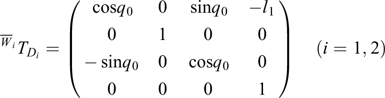
The coordinate transformation matrix of coordinate system D2 to OR and coordinate system P2 to D2 is shown in the following equations


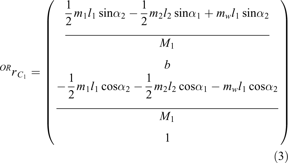
The position vector of the particle C1 in the coordinate system OR is
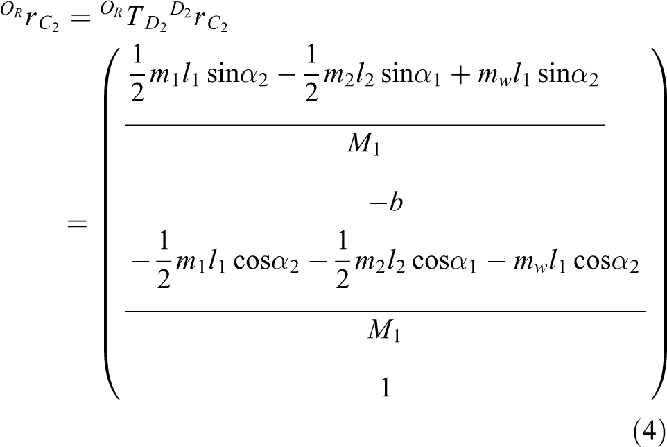
The position vector of the particle C2 in the coordinate system OR is
The position vector of the particle C3 in the coordinate system OR is

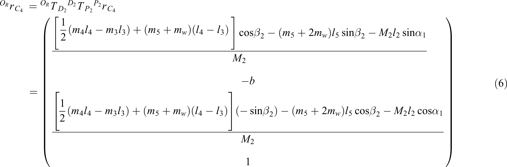
The position vector of the particle C4 in the coordinate system OR is
Name e1 and e2 as coordinate component of centroid C5 in the coordinate system OR, then the position vector of the particle C5 in the coordinate system OR is

Again using the centroid formula, the position vector of the robot’s centroid when the robot is in any motion position can be obtained as

Take β1 and β2 as 0 in formula (8), then the initial centroid position vector for lunar exploration robot can be obtained as

Centroid domain of the lunar exploration robot
Based on the above calculation, formula (8) can be concluded, since the structure of the robot is located along the XRORZR plane symmetry of the body coordinate system, so the YC coordinate of the robot’s centroid is 0. Thus, in the moving process of the robot, the centroid of the probe is always changing between the left and right symmetrical plane, so the centroid domain of the robot is a plane area. Take

The centroid domain radius of the lunar exploration robot is obtained as

Kinematic model
The rocker suspension works as a hinge link structure that helps the robot move on the lunar surface. During the moving process, the relative position of the rocker arm and forearm is in a constant state of change. The relative position of the rocker arm and forearm can be used to calculate the angle between forearm and arm relative to the horizontal plane. When the lunar exploration robot travels over rough pavement, the suspension on both sides of the location is asymmetric; therefore, we can set respective angles of wheels of w1 and w2 as q1 and q2 and angles of wheels of w3 and w4 as q3 and q4. As we can learn from the mechanical structure of the rocker, the angles of wheels of w5 and w6 are q3 and q4. At the same time, we set initial value of the angle between the robotic forearm and the road surface when robot is at the level of the road surface at q0. Since both sides of the forearm and body are together, we can see q1 = q2.
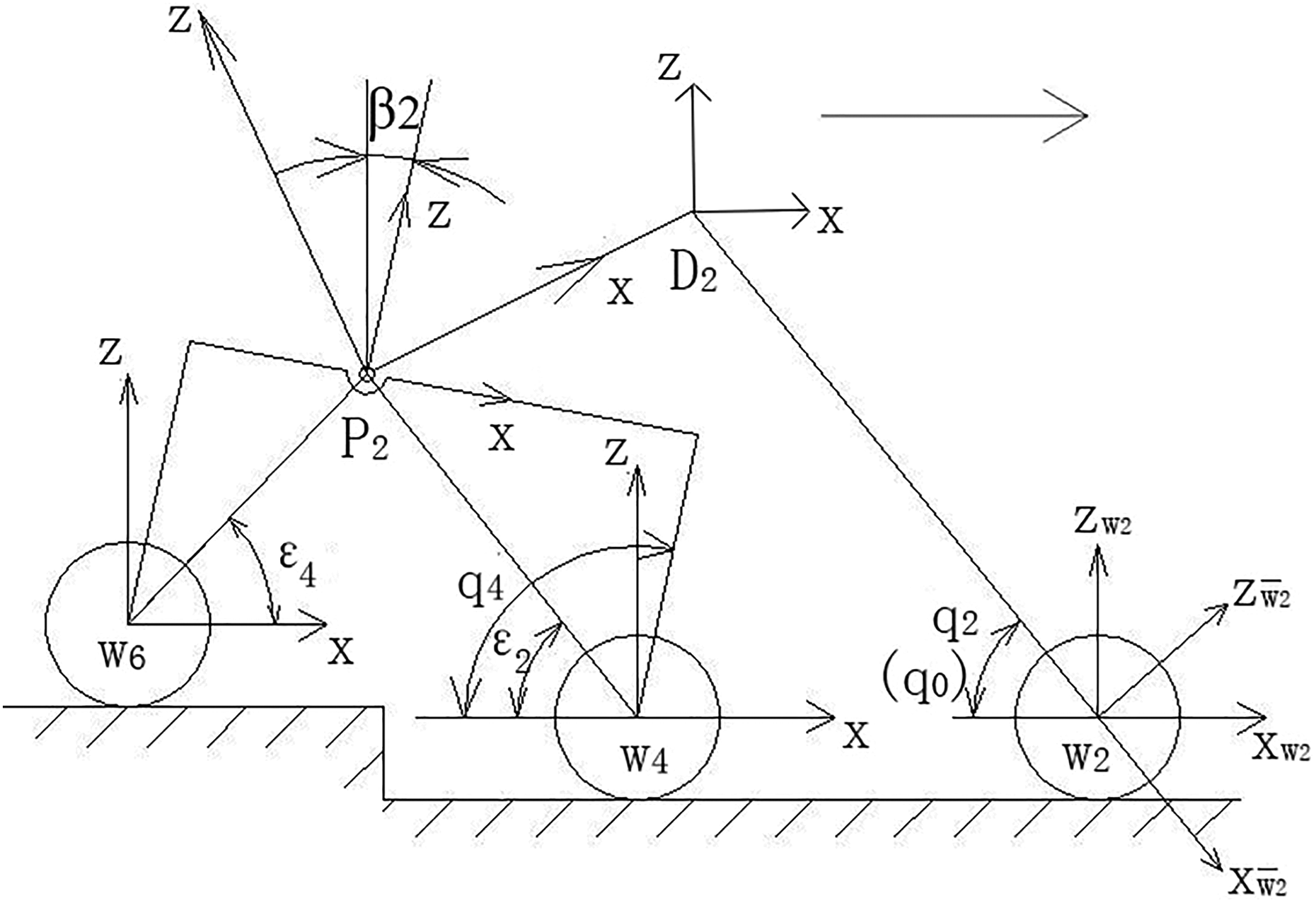
As shown in Figure 3, we establish a coordinate system Bi fixed on the lunar surface at the contact point between the wheel and the lunar surface. The direction is defined as the axis XBi is along the tangential direction of contact point and the axis ZBi is along the normal direction of contact point. We define a coordinate system Wi fixed to the wheel shaft in the center point of the wheel, XWi is in the horizontal direction, and ZWi is in the vertical direction. Meanwhile, we define a transitional coordinate system

Contacting coordinate of the wheel and the lunar surface. (a) ρi > 0 and (b) ρi < 0.
The coordinate transformation chain (Figure 4) and the conversion of coordinate systems when the robot is crossing obstacles (Figure 5) show that coordinate transformation from C to Bi (i = 1,2,…,6) is

Robotic coordinate transformation chain.
Conversion of coordinate systems when robot is crossing obstacles.
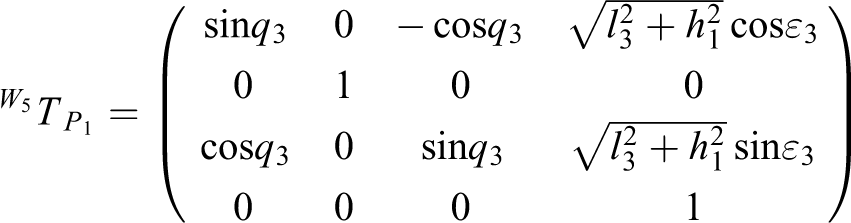
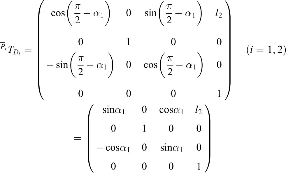
In turn, we can get specific expression of homogeneous transformation matrix of formula (13). 1. expression of

2. expression of

3. expression of
4. expression of

5. expression of

6. expression of

7. expression of
8. expression of

9. expression of
10. expression of

Then from the expression of (1) to (10) we can get
The position and orientation vectors of the coordinate system C in the world coordinate system W fixed on the lunar surface are

Homogeneous transformation matrix from C to W is

Similarly, Homogeneous transformation matrix from Bi to W is
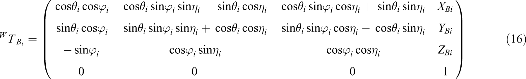
Therefore, homogeneous transformation matrix from C to W is

We bring formulas (13), (15), (16) to (17), finally, we can get general form of body position and attitude equation when lunar exploration robot is at arbitrary motion position is
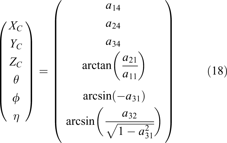
In formula (18), θ∈(−π/2, π/2), amn (m, n = 1, 2, 3, 4) represents an element of the m-th row n-th column of the matrix. The position and attitude of each wheel and the motion parameters of the suspension are determined by the lunar exploration robot in any position.
Taking the side branch of the wheel 1 as an example, the specific expressions of the vertical displacement ZC and the pitch angle ϕ are given, and the rest of the wheels are similar to that, we will not list them one by one here


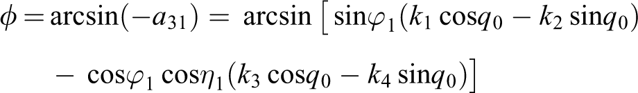
Among them

Analysis of physical lunar-detecting robot
The following are parameters of the robot: l1 = 0.480 m, l2 = 0.130 m, l3 = 0.125 m, l4 = 0.180 m, l5 = 0.145 m, m1 = 0.39 kg, m2 = 0.11 kg, m3 = 0.10 kg, m4 = 0.14 kg, m5 = 0.12 kg, mw = 0.30 kg, M3 = 10 kg, α1 = α2 = 50°, e1 = 0.030 m, and e2 = 0.040 m.
According to formula (9) and the data above, the initial center of mass of lunar exploration robot in horizontal plane can be obtained as
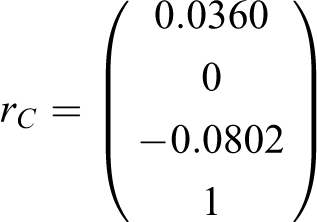
Namely, the coordinates of the initial center of mass in the coordinate system OR are x0 = 0.0360 m and z0 = −0.0802 m, and the model of radius vector of initial center of mass is rC = 0.0879 m.
According to formula (8) and the parameters of the lunar exploration robot, the center of mass at any position of the lunar exploration robot can be obtained as

According to the suspension’s geometry relationship, the value range of β1 and β2 can be obtained as

When the lunar exploration robot moves at any movement position, the variation curve of centroid vector modulus R to β1 and β2 can be obtained by MATLAB (see Figure 6).

The change curve R about centroid vector model to β1 and β2.
As shown in Figure 6, when the β1 or β2 increases gradually, R increases first and then decreases.
According to formula (19), the centroid vector modulus R of lunar exploration robot is a function about β1 and β2, hence maximum of R can be obtained; namely, the minimum of −R can be obtained too.
Assume
Variables x=(x1 x2)T = (β1 β2)T
The objective function f(x) = −R
Constraint condition

Therefore, the optimization mathematical model shown as follows

Formula (20) belongs to the linear optimization problem with inequality constraints; hence, the answer can be solved by the fmincon function in MATLAB optimization toolbox. The optimal solution for the design variables is x = (−0.1726, −0.1726)T.
At this time, the maximum of the centroid vector modulus is R = 0.0883 m.
Lunar exploration robot entity optimization design
According to the context, the center of mass of lunar exploration robot in the process of marching is always transformative in the left and right symmetrical plane and the centroid domain is a planar area. When moving on the rugged lunar surface, the smaller the fluctuation range of the center of mass, the better the performance of the car movement smoothly and the stronger anti-jamming ability of the robot has. Therefore, it is important to optimize robot arm size, the centroid domain radius, and the centroid fluctuation range for the lunar-detecting robot.
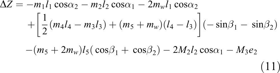
According to formula (8) and (11), it is shown that the center of mass of the lunar exploration robot on the Z-axis fluctuates smallest, namely the |▵Z|/M value is minimum. According to the context, −0.233π ≤ β1 ≤ 0.154π, −0.233π ≤ β2 ≤ 0.154π. Assume 0.10 cm ≤ l3 ≤ 0.20 cm, 0.10 cm ≤ l4 ≤ 0.20 cm.
Variables x = (x1 x2 x3 x4)T = (β1 β2 l3 l4)T
The objective function
Constraint condition

Therefore, the optimization mathematical model is shown as follows

Formula (21) belongs to a multi-objective optimization problem; hence, the answer can be solved by the fgoalattain function in MATLAB optimization toolbox. The optimal value can be obtained as

Namely, when β1 = β2 = 0.0000 rad, l3 = 0.20 m, and l4 = 0.20 m, we can learn the radius of centroid domain of lunar exploration robot R = 0 m, the Z-axis coordinate of the center of mass in the coordinate system OR is −0.0792 m. Optimization results show that when l3 = l4 = 0.20 m, the centroid domain radius is minimum in any road condition, centroid range minimum, and the anti-jamming ability strongest at the same time.
Simulation analysis of the motion of lunar exploration robot
In ADAMS, we establish the simulated motion of lunar exploration robot that drives on uneven terrain. The movement of the lunar exploration robot on the earth model is shown in Figure 7.

Operating map of the robot in the earth model.
Through the simulated analysis of the initial value and the optimal value, we get the change curve of the vertical displacement ZC and the pitching angle ϕ before and after optimization, which are shown in Figures 8 and 9. From Figure 8, the vertical displacement of the barycenter of the lunar exploration robot varies from 498.75 mm to 76.88 mm before optimization and varies from 495.28 mm to 86.39 mm after optimization. From Figure 9, the pitching angle of the car body of the lunar exploration robot varies from 18.50° to −31.06° before optimization and varies from 18.19° to −30.25° after optimization. Thus, it can be seen that the posture change of the lunar exploration robot reduces after optimization. Above all, according to Figures 8 and 9, after the optimization of the rocker arm suspension, the vertical displacement and the pitch angle of the robot have been reduced, and the stability of the integrated motion is obviously enhanced.

Before and after the optimization of the vertical displacement.

Before and after the optimization of the pitching angle.
Conclusion and future work
It established the mathematical model of mobile performance parameters for lunar exploration robot in this article. The multi-objective optimization of suspension design parameters is carried out using MATLAB optimization toolbox, and the design parameters of suspension with better relative mobility are obtained. Then, the simulation analysis is carried out in ADAMS, and the correctness of the optimization results is verified. The main conclusions are as follows:
A centroid domain model is established for the detection robot and the formula to calculate the region of the barycenter of the lunar exploration robot in any movement position is given.
In the process of the lunar exploration robot’s movement, the barycenter only varies in the bilateral symmetry plane and the region is a certain region of a plane.
As the rotating angle of the rocker arm on both sides increases, the module of the centroid vector increases first and then decreases.
The centroid fluctuation range of lunar exploration robot is minimum when l3 = l4 = 0.2 m. Thus, the anti-interference performance of the car body is best. According to the optimization results, the prototype is further perfected.
In this article, the environment of the robot is based on the laboratory environment. The complexity of the environment between the moon and the lab is different. The environment, climate, and topography of the moon are more complicated, which may cause the robot to fail to function properly. In the development of lunar exploration robot, it will gradually develop from single to multiple cooperative tasks. The cooperative operation can make each vehicle clear division of labor to a great extent, thus improving the stability and flexibility of the whole detection system. Cooperative operations, communications, navigation, and so on are the key issues in this field.
Footnotes
Acknowledgements
The authors express their sincere and heartfelt thanks to the editor and reviewers for their constructive suggestions to improve the quality of this article. In the revision of this article, Lv Qi consulted a large number of references, modified the syntax errors and figures.
Declaration of conflicting interests
The author(s) declared no potential conflicts of interest with respect to the research, authorship, and/or publication of this article.
Funding
The author(s) disclosed receipt of the following financial support for the research, authorship, and/or publication of this article: This work is financially supported by the Chinese Fundamental Research Funds for the Central Universities under grant no. 2014YJ02, National Undergraduate Innovation and entrepreneurship training program under grant no. 201611413086, Beijing college students innovation training project under grant no. K201504024, Beijing cross training program for high level talents in higher education institutions in 2017, The Innovation training project of China University of Mining and Technology (Beijing) under grant no. K201504016, and so on.