
Abstract
Human-oriented robots should be human-friendly, safe and impact-free. The present work is about the problem of adjustable compliance implementation in human-friendly robots. A new passive compliance adjustable compliant joint based on a variable length leaf torsion spring is presented. It allows a wide range of independent positioning and stiffness regulation. Some characteristics of the leaf torsion spring are analysed: stiffness\compliance, torque, elastic deformation angle and generated potential energy. Numerical simulations are performed. The structural parameters' influence on the compliant joint's characteristics is estimated. Tests on a specially realized prototype of an adjustable compliant joint are carried out. The basic prototype characteristics are evaluated. The experiments show a very good correlation with the numerical simulations.
1. Introduction
Today, robots are not only designed for industrial tasks, but also new tasks such as interactive operations with humans: rehabilitation, prosthesis, surgery, entertainment, offices, domestic assistance, etc. In this context, the new generation of robots has to be designed in such a way that all contact with humans is injury-free. The basic problem is compliant motion realization of the so-called human-friendly robot. The human ability to vary the joint stiffness is the main reason for both successful and safe interaction with the surrounding environment.
The admittance or impedance control scheme [1] is the first known solution for compliance or stiffness adjustment. In this solution, the relation “displacement - force” of the end-effector is controlled, using position controllers by introducing an external chain closed by a force sensor. This is an active approach, which guarantees a wide range of compliance variation. However, it does not ensure a high level of safety, due to low resolution or noise in the sensors, long calculation time and servo system instability.
Passive compliance, being independent of servo-responses, is reasonable for the implementation of increased safety for human-oriented robots. In such robots, the so-called “serial elastic actuation” (SEA) is often used [2]. The high impedance values are limited to the elastic link stiffness values. These values are realized by an elastic element, a torsion spring, with a constant stiffness implemented between the driving motor and the driven arm.
This technology is suitable for wearable powered robots to solve safety issues and to reduce the inherent output impedance. In [3], the design of a light-weight active pelvis orthosis with two actuation units is presented, employing a series of elastic actuator (SEA) architecture. The SEA is realized by a torsion spring, which achieves a stiffness of 100 Nm/rad. In this case, the actuation is not rigid and allows minimum joint output impedance across the frequency spectrum of gait. Variations in the output impedance are achieved by closed-loop control strategies.
This actuation is a combination of both the active and passive approach for impedance variation, because a feedback for regulation of the output torque in the driving system and the spring system is used, except for a compliant element. One of the drawbacks of the elastic actuator is its low frequency range for control, due to the low torsion spring stiffness. This is the reason why auxiliary actuators should be implemented and an approach for compliance regulation should be used [4]. Robots possessing adjustable passive compliance are redundant. Some approaches to redundant actuation for passive compliance adjustment have been discussed in the literature.
The structure-controlled stiffness approach for passive compliance realization [5] is based on manipulating the effective structure of the spring, by changing some of its structural parameters, such as length, thickness and width. In this purpose, an additional actuator for stiffness variation of a passive compliant element is added in each joint, except the actuator for joint position control. A solution for an actuator, based on the structure controlled stiffness concept called “Jack Spring Actuator”, where a helical spring is used as a compliant element, is presented in [6]. The active coil length can be changed by inserting an axis into the spring, with a surface that can slide between the rings of the spring. The spring structure consists of many layered sheets in the solution presented in [7]. Thus, the idea is to increase the element stiffness by pressing the sheets together. A similar solution, known as “Mechanical Impedance Adjuster”, is presented in [8], where a leaf spring compliant element is mounted in the joint. The joint stiffness is varied by means of displacement of a slide mechanism by changing the application point of the bending force. In the so-called “Mechanically Adjustable Compliance and Controllable Equilibrium Position Actuator”, or MACCEPA [9], the variation of the compliance is based on the pre-tension variation of a torsion spring situated in a lever mechanism. The control of the compliance and equilibrium position are fully independent and these control signals are independent of the current position. In [10], a mathematical description of the actuation principle, along with an experimental verification of its performance in a powered ankle–foot prosthesis, is revealed. A disadvantage of this approach is that the stiffness of the MACCEPA actuator is limited, due to the inelastic deformation of the spring.
In the “Variable Stiffness Joint” [11], two motors of different power change separately the link position and the stiffness. The high power motor that changes the link position is connected to it via a harmonic drive gear. The joint stiffness is changed by the low power motor, which changes the characteristic of the supporting mechanism.
A novel mechanism is used to regulate the compliance in the solution “Actuator with Adjustable Stiffness” [12]. This is performed not through the tuning of the pretension of the elastic element, but by controlling the fixation points of the elastic elements (springs). For this purpose, a linear drive is used, which tunes the stiffness based on the variable arm. However, to achieve a wide stiffness variation, this concept may require a lever arm with a reasonable length, which increases the size of the overall variable stiffness actuator. In the “Compact variable stiffness actuator” (CompAct-VSA) [13], the stiffness adjustment is performed by a cam-based lever arm, with variable pivot. The mechanism employs permits to increase substantially the range of the achievable stiffness, requiring a shorter lever arm and smaller springs compared with previous solutions, which effectively reduce the size of the CompAct-VSA.
The antagonistic compliance adjustment approach is based on the use of nonlinear springs (force proportional to the square of deflection) allocated linear to the joint. Two actuators are used in this case for the drive of one single rotation joint. The joint stiffness is a function of the actuators' preliminary pressure, by means of which it is modulated. This scheme allows decoupled stiffness and displacement joint control by position control of two actuators. Research activities in [14] are aimed at testing this control strategy with robots involved in human-robot cooperation tasks, as in assistive robotics applications. For example, both the NEURARM shoulder and the elbow joints are driven by a pair of antagonist actuation units. In [15], authors introduce NEUROExos, a novel elbow-powered exoskeleton designed for post-stroke rehabilitation of the arm, ensuring maximum comfort and safety for the patient. NEUROExos is powered by an antagonistic-driven compliant joint (ADCJ). In this decision, there are remote locations of both the non-linear springs and the actuators and its transmission system is based on tendon wires. Indeed, tendon wires introduce undesired elasticity in the actuation unit. Problems also arise when designing a convenient quadratic spring.
A simple and compact perfect design, combining stiffness ranging from very high to low, with easy to control stiffness and position, has not yet been proposed, although various solutions for compliance actuators have been developed.
In this context, the objective of the work presented in this paper is to propose a new design for a compliant joint with a structure-controlled compliance, according to the passive approach. The proposed design of the compliant joint will allow a wide range of stiffness regulation and precise positioning by decoupled control of stiffness and position. The aim is also to present the compliant joint design and its basic characteristics. Numerical and physical experiments are performed and the basic joint characteristics are deduced.
The results of this study may be useful for designers and manufacturers, allowing them to develop and design human-oriented devices, such as service robots, medical robots (assistive devices and rehabilitation orthoses), exoskeletons and wearable robots, and robots for entertainment (toys, pets, guides), among others.
The rest of the paper is organized as follows: the development of a new adjustable compliance joint with torsion leaf spring is presented in Section 2. The compliant joint's design and its main characteristics and an analytical and computer assessment are also presented in this section. The performed experimental evaluations are presented in Section 3. Here, a prototype of the adjustable compliant joint is revealed and experimental evaluation of its main characteristics is presented. Finally, conclusions, discussions and future work on the proposed design are presented in Section 4.
2. Torsion Leaf Spring Adjustable Compliance Joint
2.1 Adjustable compliance joint design
The objective is fulfilled by the innovative design of an adjustable compliant joint, with a structure-controlled compliance, based on a torsion spring, as shown in Figure 1.
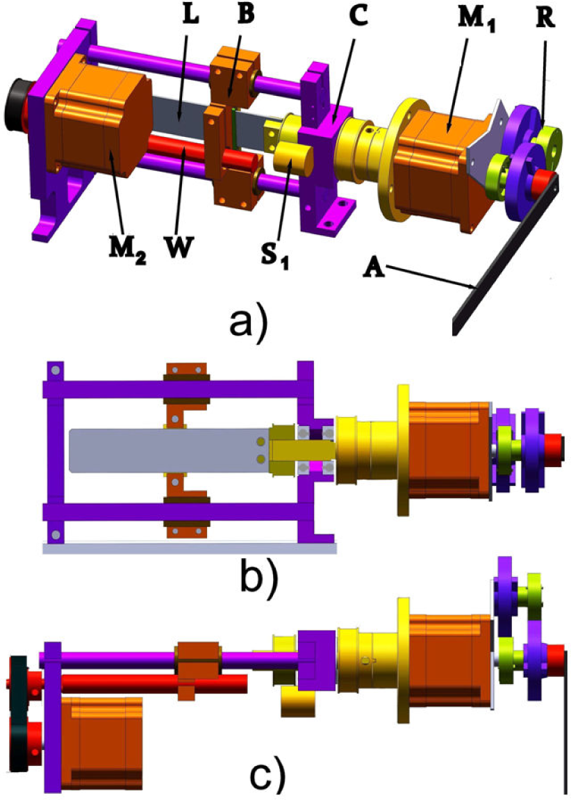
Adjustable compliance joint design with torsion spring: a) general view, b) side section view, c) top view
The joint includes base housing C, through which a shaft passes, connected to a torsion spring L on one side and to the motor M1 and the reducer R on the other side. The effector (arm) A is mounted at the output of the reducer; its axis of rotation coincides with the axis of torsion of the spring L. A digital encoder (sensor) S1 is located on the housing for measuring the spring torsion. A second motor M2 and gear are mounted on the other part of the housing base, which drives a leading screw W, used to lead a barrier B, which is sliding on two parallel guides on the base and is also sliding among the spring, determining its free length. When the spring is twisted, its axis of deflection and axial torque coincide. Compliance is controlled by altering the length of the thin rectangular torsion spring L, by moving the barrier B, through motor M2 and screw W. The angular position of the arm A is controlled by motor M1. Thus, the proposed compliant joint is a system of two degrees of freedom, which is controlled by two motors: M2 for stiffness adjustment and M1 for arm position.
This design is innovative due to the fact that the length of the joint torsion spring is variable, unlike the serial elastic actuation, for example. This improves the performance of the compliance joint. The stiffness varies from very high to low, allowing precise positioning at high stiffness or reduction of the contact force and the motor torques at lower stiffness.
2.2 Compliance joint's basic characteristics
The basic characteristics that define the design of the compliant joint are: stiffness; compliance; allowable load torque; maximum angle of the spring twist and capacity for storing energy.
The deformation in the joint is represented by the angle of twist ϕ on the axis of the leaf spring (width h and thickness t). When h / t > 10, the angle of twist of the torsion spring is determined by [16]:

where:
T – load torque along the spring axis,
L – active spring length,
G – shear modulus of rigidity.
Stiffness in the joint torsion spring expresses the ratio of the loading torque T to the received angular deformation of the spring ϕ:

The compliance B, being the reciprocal function of the stiffness, is:

The allowable load torque of the joint is determined by the permissible torsion stress (shear stress) τmax of the spring:

The maximum angle of spring twist is determined according to (1) for maximum torque (4):

The potential energy stored in the elastic joint due to the spring deflection is:

Considering that the load torque is a function of the spring's stiffness and the deflection (2), the potential energy becomes:

Note that the maximum potential energy that can be generated at a certain stiffness is determined by the maximum permissible angle of spring deflection ϕ = ϕ max
2.3 Computer assessment of joint characteristics
Numerical experiments are carried out by changing some of the structural parameters of the leaf spring: length L, thickness t and width h, in order to assess the compliant joint's basic characteristics. The influence of these parameters on the stiffness change of the spring was studied according to eq. (2). The selected material of the leaf spring is titanium alloy Ti-8Mn Annealed with shear modulus of rigidity G = 4.9 1010 N/m2 and bending strength (yield strength) σ y = 8.1.108 N/m2. The influence of changing the length in the range of L = [0,0005 – 0 09] m on spring stiffness K and compliance B for t = 0.001m and h = 0.018m is shown in Figure 2.

Effect of structural parameter length L on: a) spring stiffness K; b) spring compliance B
The spring length L creates a proportional influence on the compliance of the joint according to eq. (3) and a reciprocal influence on the stiffness according to eq. (2). Equation (2) gives a theoretically infinitely high stiffness for L near 0 (zero). This property is the foundation for creation of the adjustable compliant joint, where compliance can reach the value of zero. Note that the actual value of the compliance in the joint cannot reach zero, because it is determined by the compliance of the structure, the engine and the transmissions. The presence of a barrier chamber also prevents the total hardening of the joint. Hence, for a spring with thickness t = 0.001m, and width h = 0.018 m, in the length range L = [0.0005–0.09] m, the resulting stiffness variation is K = [588 − 3.2667] Nm / rad and compliance B = [0.0017 −0.3061] rad / Nm.
Increasing the values of some parameters, such as the width and the thickness of the spring, leads to an increase in stiffness. However, complete hardening of the joint cannot be achieved in this way. Thus, the value of these parameters will be primarily determined by considering the strength.
Similarly, increasing the width of the spring, as well as its thickness, leads to increasing the maximum allowable torque (4). The maximum allowable torque Tmax is not affected by changing the length L (4). Its maximum value is Tmax = 2.43 Nm for the leaf spring (width h = 0.018 m and t = 0.001 m). In eq. (4), the permissible torsion stress τ max is regarded as half of the eligible yield stress σ y of the material used (Ti-8Mn Annealed), or τ max = 4.05.108 N/m2.
Numerical experiments were performed using Finite Elements Analysis (FEA) by the SolidWorks Simulation system, to check this assertion. The spring was clamped at one end and a shear torsion static load T = 2.43 Nm was applied at the other end. The program computes the maximum shear stress in the middle of the wide side τ xy = 3.5.108 N/m2, as shown in Figure 3.

FEA effective shear stress analysis
The permissible torsion stresses τ x max = 4.05.108 N/m2 and the results for the maximum angle of twist variation, while changing the structural parameters according to (5), are shown in Figure 4:

Effect of structural parameters: a) length L and b) width h on the maximum angle of twist ϕ max
The maximum permissible angle of spring twist ϕ max is proportional to its length and for L = 0.09 m and t = 0.001m it reaches ϕ max = 0.743 [rad]. It does not depend on the width of the spring h. As stated previously, this property is used to create a compliant joint with an increased load capacity and a large elastic deformation, using a spring with a wide sheet or made up of different sheets.
The required load capacity is determined by the width and the thickness of the leaf spring in the proposed solution for the adjustable compliant joint. The necessary compliance is achieved by amending the third structural parameter, namely the length of the torsion spring L.
3. Preliminary experimental evaluations
3.1 Prototype of the adjustable compliant joint
A prototype was realized of an adjustable compliant joint with a leaf spring, made of titanium alloy Ti-8Mn Annealed with the material properties listed above, in order to evaluate experimentally the main characteristics of the joint.
The realized prototype is shown in Figure 5. The length L of the leaf spring ranges from 0.0006 − 0.05 m and the thickness t and width h are defined as 0.001 m and 0.018 m, respectively. The spring is connected at one end to a shaft fixed to the motor M1, reducer R and output lever A, and at the other end to barrier B, which changes the working length of the spring.

Prototype of the adjustable compliant joint
A screw gear W is used to move the barrier B, driven by the second motor M2. The deformation of the spring is measured by the digital encoder S1. Identical step motors are mounted with step of 1.8°. The ratio of the spur wheel reducer connected to M1 is u = 7.053.
3.2 Experimental evaluation of the adjustable compliant joint characteristics
The performed experiments are based on the method presented in Section 2.2. According to eq. (1), the angle of spring deformation is changed proportionally to the variation of the spring length at a constant loading. During the experiments, the twist deformation of the spring is varied by changing its length, when motor-reducer M1-R is locked (in a given position) and two constant loads P (P = 5 N and 10 N) are applied at the output lever (arm).
As a result of the spring twist deflection, the torque in the joint is:

where l is the length of the lever and ϕ is the deflection angle of the lever.
The torques Te for these loads are 1 and 2 [Nm], respectively, when the lever is found initially in a horizontal position (ϕ = 0°) for length l = 0.20 m. At the beginning, the joint is rigid. The rotation angle of the arm is zero and the stiffness starts to change slowly from high to low, by moving the slider (L = 0.0006,…, 0.05 m) and then back again, as the experiment is repeated several times. The desired length of the spring is controlled by the course of the motor M2. The deformation of the spring (angle of twist ϕ) is measured by encoder S1. The angle ϕ as a function of the length L of the spring under two loadings is shown in Figure 6.
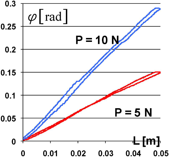
Experimental reporting of the spring torsion ϕ when changing the length L for the load values: P = 5 and 10 N, respectively
As seen, the experiment shows the presence of hysteresis. The hysteresis is a result of friction and clearances of the barrier. The experimental data allow calculation of the stiffness K, according to (2) and (8):

The calculations are performed for each of the above experiments (with P = 5 and 10 N). The theoretical and experimental results for regulation stiffness K and the corresponding compliance B are shown in Figure 7a) and Figure 7b), respectively. The ranges of K and B are [6.62; 535] Nm/rad and [0.1511; 0.0019] rad/Nm, respectively.

Experimental and theoretical results of: a) stiffness K and b) compliance B
The experimental load torque-deflection graphs, for different values of K (6.62 – 535) Nm/rad, are shown in Figure 8. It is seen that the working area of the allowable loading torque is within the boundaries of [-2.43; 2.43] Nm/rad and the admissible angles of elastic deformation are within the boundaries of [-0.367; 0.367] rad.

Loading torque-deflection graphs of the adjustable compliant joint under different stiffness values
The potential energy, as a function of the spring deflection under different stiffness values, is presented in Figure 9. As can be seen from the graphs, more energy is accumulated at high compliance levels, wherein the permitted spring deflection is bigger. For stiffness K = 6.62 Nm/rad, for instance, the maximum allowable angle is ϕ max = 0.367 rad and the stored energy E = 0.446 J.

Potential energy in the compliant joint, as a function of the spring deflection under different stiffness values
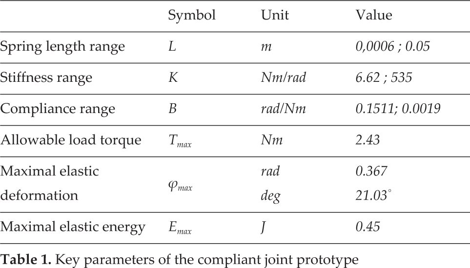
All the principal characteristics of the realized adjustable compliant joint are summarized in Table 1. The compliance joint's experimental values parameters essentially coincide with the theoretical. Here, the stiffness adjustment range is different in the two cases. Globally, the range obtained theoretically includes the experimentally achieved. The different adjustment ranges are due to the limits set by the design of the main input parameter - the length of the spring. Unlike the theoretical results, the experimental results indicate the presence of hysteresis, which is a result of deficiencies in the prototype design, such as friction and gaps in the barrier.
Key parameters of the compliant joint prototype
4. Conclusions
In this work, an innovation design of an adjustable compliant joint was investigated. This design is characterized by a structure-controlled compliance, based on a leaf torsion spring with variable length. The proposed design of the compliant joint will allow a better performance of the joint, including a wide range of stiffness regulation at decoupled stiffness and position control.
The main characteristics of the spring, such as stiffness, compliance, allowable load torque, allowable angle of deflection and the generated potential energy are analysed. Computer assessment of the main characteristics was carried out in order to evaluate the influence of the spring's structural parameters.
The performed computer simulation, based on the proposed analytical model, shows that by modifying the principal structural parameter of the spring, namely its length, a wide range of adjustment of the joint stiffness is achieved. The required load capacity is determined by the other structural parameters: width and thickness of the leaf spring.
Prototype experiments were performed in order to test the compliant joint design. The main characteristics of the prototype, range of stiffness variation and maximum angle of the elastic deflection, were examined. The experimental values of these parameters coincide with those of the calculations. The experimental results confirm the conclusions - that the proposed solution for the compliant joint allows a wide range of stiffness adjustment. The reported presence of hysteresis is due to deficiencies in the realization of the prototype.
The studies carried out allow us to conclude that the proposed compliant joint solution allows stiffness adjustment by a first motor and an independent positioning of the driven link by a second motor. Reduction in the contact force and the motor torques can be achieved by decreasing the stiffness. On the other hand, joint hardening and arm precise positioning can be achieved by increasing the stiffness. Thanks to the compliance adjustment, the response to the force interferences is adjusted, thus ensuring interaction safety. Consequently, designing a compliant robot with the proposed compliant joint supposes a high robustness of motion, with respect to unexpected disturbances on the one hand and natural human safety on the other hand.
The proposed design solution for the adjustable compliance joint can be used in various applications, such as service robots, medical robots (assistive devices, rehabilitation robots), exoskeletons and wearable robots.
For any application, a torsion spring with an allowable loading torque for adjusting the stiffness must be selected. The second key parameter is the minimal stiffness that is achieved. These two parameters determine the required length of the spring, which defines the dimensions and the weight of the device.
If the size and weight of the compliant joints are not suitable for placing it directly on the arm links, they can be mounted on the base of the arm using a tendon transmission or Bowden cables for transmitting the torque and movement. This solution is very suitable for service robots that combine a motorized base platform and a robot arm. The deployment of adjustable compliance joints on the platform allows safer mobility and manipulation, using the advantages of adjustable compliance. A service robot with compliant joints allows adjustment of end effector compliance where collision with a human or unknown obstacle is possible. The adjustment of the robot end effector compliance is subject to future research by the authors.
Future work should be completed on the creation and testing of a new, more elaborate prototype of an adjustable compliance joint. It must include gap-free locking of the spring, reduction of the friction in the barrier, lighter motors and new housing realization.
Footnotes
5. Acknowledgements
This work was funded by the European Commission through FP7 Integrated Project VERE - No. FP7 −257695, to which the authors would like to express their deepest gratitude.