
Abstract
Design of a new differential-velocity–type compliant joint with two motors is proposed for robotic manipulators. The speed/output torque of the differential-velocity–type joint is synthesized by controlling the differential speeds of a pair of actuators. Descriptions of the design concept, theoretical analysis, and the experiments are presented in this article. The experimental results showed that (1) the stiffness of the differential-velocity–type joint can be regulated by changing the speeds of both motors, (2) the differential-velocity–type joint actually reduced 7.9%−15.7% time compared with the single-drive joint when performing five cycles of reciprocation, and (3) a new design of delta-type robot with differential-velocity–type driving modules was developed for verification. The experimental results showed that the differential-velocity–type delta robot can perform flexible assembly operations within a 0.028-mm tolerance.
Introduction
While robots deal with tasks, not only the precision positioning of robot manipulators but also the safety issue of the human–machine interaction should be considered. Concerning on the safety issues of preventing human operators or objects from damages by the robotic manipulators, there have been more and more researches and developments focused on the compliance issues of manipulators recently. To control the contact force of the robotic manipulators, elastic actuators with a motor and a spring were designed.1,2 Researches on using variable stiffness actuators with two motors and one elastic element have also been carried out in previous studies.3–9 However, because the performance of the elastic element is similar to the function of a low-pass filter, the bandwidth of the elastic actuator is limited. Therefore, some designs of the joints driven by dual actuators and a gear transmission mechanism have been studied for robotic manipulator. A dual actuator unit (DAU) has been studied in Kim et al.,10,11 where the position control of the DAU is adopted by a high-torque and low-speed motor, and the stiffness of the DAU is modulated by a low-torque and high-speed motor. When an unexpected collision occur, the joint stiffness of DAU could be adjusted rapidly by the low-torque and high-speed motor. Similarly, a hybrid variable stiffness actuator (HVSA) with two operation modes was developed in Kim and Song. 12 One mode was a rigid mode as a conventional stiff joint. The other mode can provide a wide range of stiffness and rapid responses according to the change in the stiffness under varying loads. Also, another type of variable stiffness actuator (VSA) by controlling the ball screw mechanism to vary the stiffness of actuator was discussed in Sardellitti et al. 13 The effectiveness of the controller in terms of tracking performance and stiffness adjustment was verified. Moreover, in addition to control the stiffness of actuators, a dual motor system using a planetary gear (DuPG) was developed to improve the speed–torque performance in Lee and Choi. 14 The DuPG combined two motors with one planetary gear, in which one motor was designed for high speed and the other for high torque. The DuPG could generate high speed or high torque according to the environmental or driving conditions.
Referring to these related researches, two important issues of designing the compliant joint of robotic manipulators can be concluded. The first is that the stiffness of the joint should be variable, that is, the torque of the joint can be adjusted at the same angular speed. The other is that the output performance of the joint is expected to be enhanced, especially when the joint is designed with multi-actuators. Due to the two issues, a differential-velocity–type (DVT) joint was proposed to perform the variable stiffness feature and high-speed reciprocation ability. Furthermore, the DVT joint was implemented to delta robot to perform rapid reciprocation and flexible assembly in this study.
This article is organized as follows: the design concept of the DVT joint is described in section “Design concept of the DVT joint,” the theoretical output performance of the DVT joint is discussed in section “Theoretical analysis,” the experiments to verify the performance of the DVT joint are discussed in section “Experiments and discussions on the DVT joint,” the DVT delta robot constructed with three DVT driving modules is designed for a practical application of flexible assembly in section “Delta robot with the DVT joints,” and the summary and conclusions are given in section “Conclusion.”
Design concept of the DVT joint
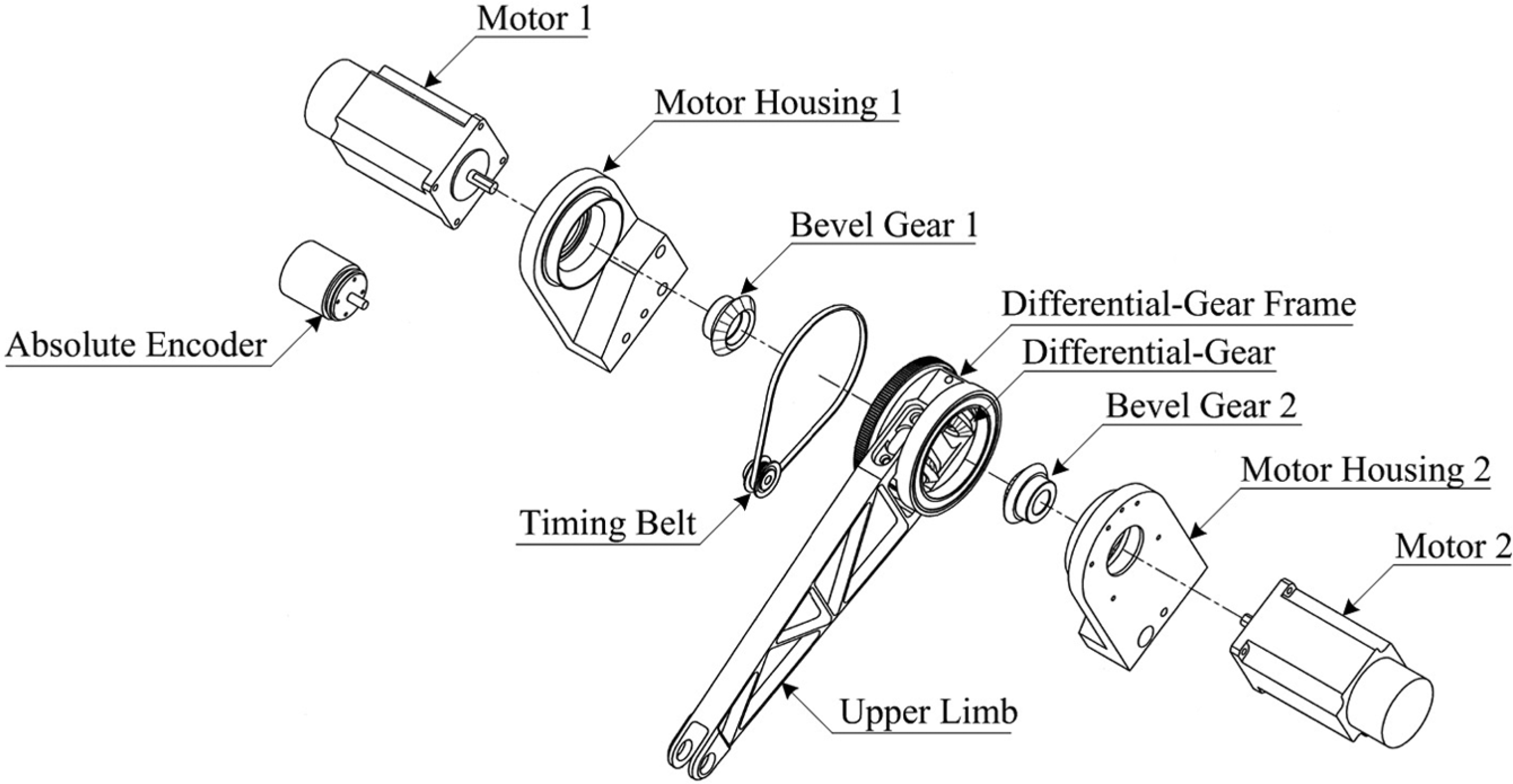
The DVT joint presented in this article is a 1-degree-of-freedom joint which is driven by two motors. The major components of the DVT joint are shown in Figure 1. Two driving sets are adopted to drive the DVT joint. Driving set 1 consists of encoder 1, motor 1, reducer 1, and bevel gear 1 mounted on housing 1. The components of driving set 2 are the same as driving set 1. Housings 1 and 2 are pivoted to each other through shaft. In addition, differential velocity gear is also pivoted through shaft and is engaged with bevel gears 1 and 2 of driving sets 1 and 2, respectively. Thus, driving set 2 relatively rotates about driving set 1. In this design, bevel gears 1 and 2 have the same gear modulus and number of teeth. Differential velocity gear has twice the number of teeth and the same gear modulus of bevel gear 1.
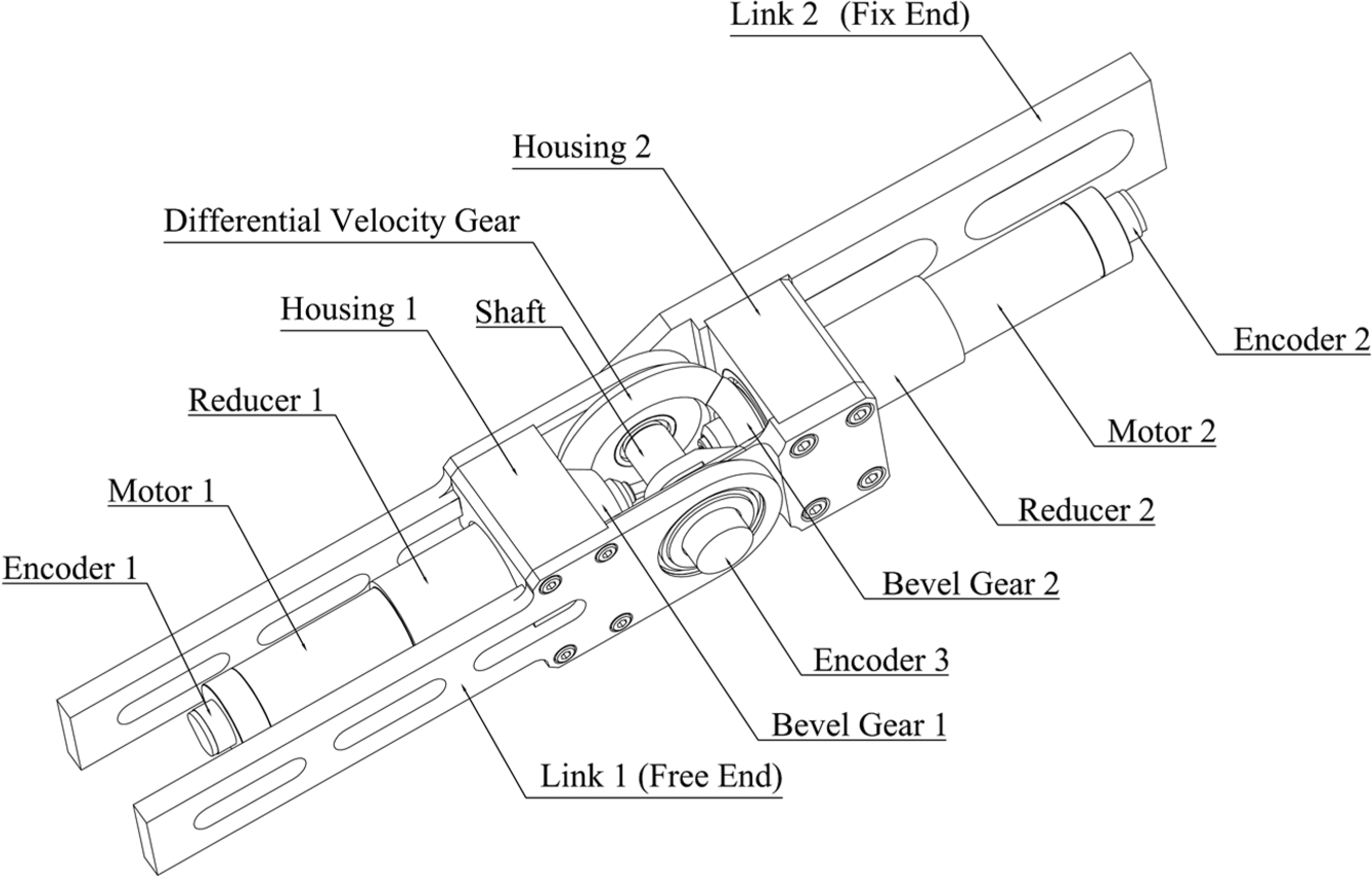
Components of the DVT joint.
The main components used in this design are listed in Table 1. The other structures are manufactured using aluminum alloy A6061-T6. The total weight of the DVT joint is 1.89 kg. Figure 2 shows the characteristic curves of the motor sets from the manufacturer. These curves are estimated under a maximum voltage of 32 V and a maximum current of 7.2 A. The relation between torque and speed can be formulated by equation (1), where

Component specification of the DVT joint.
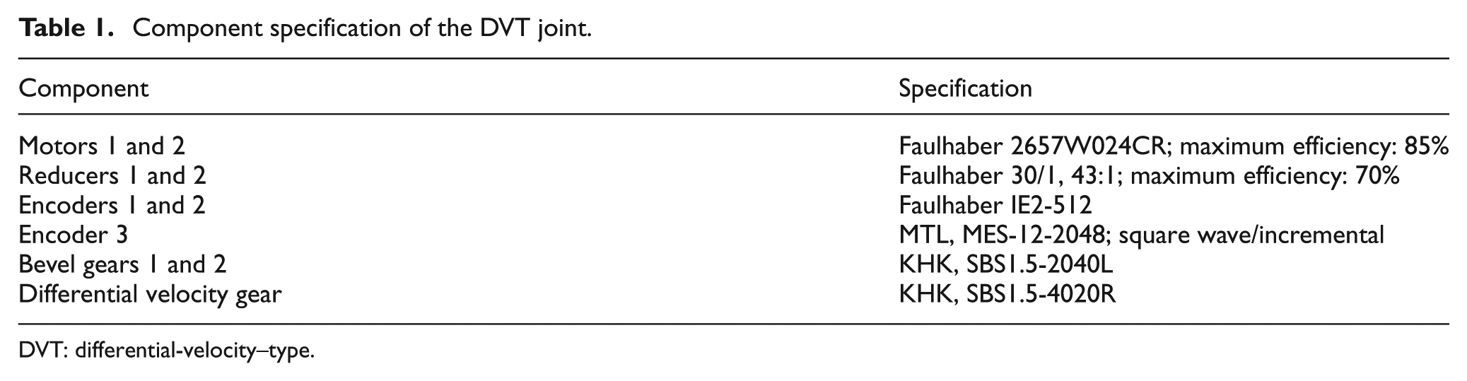
DVT: differential-velocity–type.

Main characteristic curves of the motor set of Faulhaber 2657W024CR + 30/1, 43:1.
As shown in Figure 1, link 1 connects to driving set 1 and pivots on the differential velocity gear. A link 2 connects to driving set 2 and pivots on the differential velocity gear. According to the rotating directions of the two driving sets, the DVT joint can be operated in two modes, output enhanced mode and differential velocity mode. When the two driving sets rotate in the same direction as shown in Figure 3(a), the joint is operated in the differential velocity mode. Link 1 rotates about the axis of the differential velocity gear with the speed which is the difference between the speeds of the two driving sets. The speed of the DVT can be stated by equation (2)


Two operation modes of the DVT joint: (a) differential velocity mode and (b) output enhanced mode.
where

In this article, the characteristics of the DVT joint in the differential velocity mode were studied. Furthermore, a DVT delta robot was designed by implementing the special features of the DVT joint.
Theoretical analysis
Since the speed/output torque of the DVT joint can be regulated by controlling the speeds of the two driving sets in the differential velocity mode, it is advantageous to perform a motion with different stiffness or different motions with the same stiffness. The relation between the speed/output torque of the DVT joint and the speeds of the two driving sets is analyzed in the following.
In differential velocity mode, both motors of the DVT joint are operated by velocity control. The speed of the DVT joint is equal to the difference between the speeds of the two driving sets. For example, if the speed of driving set 1 is higher than driving set 2, the DVT joint will rotate clockwise, and the speed is stated by equation (4)

where
The output torque of the DVT joint is different from that of the traditional joint and is discussed in the following. If an external torque is applied to make the DVT joint from rotation to stationary, the external torque should be large enough to slow down the speed of the higher speed motor. The current of the higher speed motor will increase to the maximum tolerant current depending on the capacity of the motor. It means that the external torque should be larger than the maximum output torque of driving set 1 as stated in equation (5)

where
In other words, the output torque of the DVT joint which is operated with the differential velocity mode equals the maximum output torque of the higher speed driving set at the desired speed as stated in equation (6)

where
Until the speed of the higher speed driving set decreases to be equal to the speed of the lower speed one, the DVT joint will remain stationary as stated in equation (7). In this status, the external torque is equal to the maximum output torque of driving set 1 where the speeds of both driving sets are the same as stated in equation (8)


Therefore, the output torque of the DVT joint can be considered as the torque against the external torque as stated in equation (9)

Due to the characteristic of motor, the motor generates higher torque with lower speed at the saturated output power. Thus, the DVT joint provides higher output torque when the speed of the lower speed driving set is lower as stated in equation (10)

According to equations (6) and (9), the output torque of the DVT joint depends on the speed of the higher speed driving set when the DVT joint rotates but depends on the speed of the lower speed driving set when the DVT joint is at stationary status. Thus, the output torque of the DVT joint operated in differential velocity mode can be expressed by equations (11) and (12)


Since the speed of the DVT joint equals the difference between the speeds of the two driving sets, the DVT joint can rotate with the same speed but can generate different output torques. Moreover, the DVT joint can generate the same output torque with different speeds. Three cases are given to be an illustration. Comparing cases A and B, the DVT joint rotates with the same speed but generates different output torques. Comparing cases B and C, the DVT joint generates the same output torque with different speeds:
Case A


Case B


Case C


Moreover, an external torque is applied to rotate the DVT joint clockwise from stationary when the speed of driving set 1 equals the speed of driving set 2 as stated in equation (13)

where
The external torque should be large enough to slow down the speed of driving set 2 as stated in equation (14). It means that the external torque should be larger than the output torque of driving set 2

Therefore, the output torque of the DVT joint that rotates at the speed of 0 r/min is equal to the output torque of driving set 2 at the current speed

Due to the characteristic of motor, the motor generates higher torque with lower speed at the saturated output power. The output torque of the DVT joint at stationary can be regulated by adjusting the speeds of both the driving sets simultaneously. For example, the output torque of the DVT joint increases when the speeds of the two motors decrease simultaneously and vice versa.
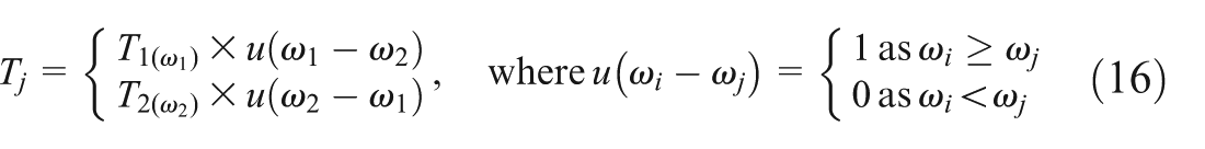
According to equations (11), (12), and (15), the output torque of the DVT joint in the differential velocity mode can be expressed by equation (16)
Based on the derivation, the theoretical speed–torque curves of the DVT joint are shown in Figure 4. The vertical line (red line) denotes the speed of the DVT versus constant output torque. The horizontal line (black dash line) denotes the output torque versus constant output speed. The oblique line (blue line) denotes the torque versus the speed of motor set 1 (higher speed motor set) with constant speed of motor set 2 (lower speed motor set). Point a (169, 0) denotes that the DVT joint is operated at the speed of 169 r/min when the speeds of the two motor sets are 169 and 0 r/min, respectively. On this chart, the overall speed versus output torque of the DVT joint can be found. Furthermore, some control strategy for safety issue could be generated from this chart. For example, there are two robot arms which are constructed with the DVT joint and single-motor-driven (SD) joint. Both of them are operated at the speed of 31 r/min. The operation points of these two robot arms can be represented as points b and c, respectively. When an object appears in the desired trajectory of the robot arms, the robot arms will be blocked by the object after hitting it. According to the characteristics of motor, the robot arm with SD joint will change its status to point c′ and may generate a torque up to 7.2 N m. The robot arm with the DVT joint will change its status to point b′ and may generate a torque up to 4.26 N m. It can be observed that the potential damage from the robot arm with the DVT joint is less than that from the robot arm with SD joint.

Theoretical speed–torque curves of the DVT joint.
Besides the feature on variable stiffness, the DVT joint can achieve rapid reciprocation by accelerating the lower speed motor set and decelerating the higher speed motor simultaneously. Figure 5 shows that there exists dead time interval when the SD joint performs reciprocation but no dead time interval in the reciprocation of the DVT joint. Thus, the damage from collision mentioned in the previous paragraph can be further mitigated by these control strategies. The status of the robot arm with the DVT joint will change to point b″. The robot arm with the DVT joint will stop by spending half the time. Especially, the output torque is further mitigated down to 3.6 N m.

Reciprocation ability comparison of the DVT joint with the SD joint.
Also, when the robot arm contacts the object, there exists an angular displacement in transient. Thus, the equivalent stiffness of the DVT joint could be defined by equation (17)
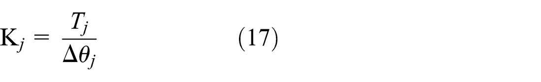
where
Experiments and discussions on the DVT joint
Control system architecture
To verify the characteristics of the DVT joint, a control system architecture which is shown in Figure 6 was established. A PC-based motion controller was developed to control the DVT joint. The motors of the DVT joint are controlled by Faulhaber motion controller MCDC 3003C. MCDC 3003C communicated to the PC-based motion controller via a controller area network (CAN) bus interface card, PCM-CAN200P-D. With dsPIC digital signal controller, encoder 3 is used to send the absolute angular displacement of the DVT joint back to the PC-based motion controller. Then, the relative speed commands of the two motors are computed with the PC-based motion controller based on the speed or stiffness requirements. In order to measure the torque of the DVT joint, a force gauge, FG-5000A, is employed to measure the contact force when the free end of the DVT joint rotates and contacts the force gauge. Then, the equivalent torque of the DVT joint can be determined.

Control system architecture of the DVT joint.
Experiment on variable stiffness
To verify the characteristics of variable stiffness, the experiment on the differential velocity mode is shown in Figure 7. One link of the DVT joint is fixed, and the free end of the DVT joint rotates to point A until contacting the force gauge.

Experiment setup of variable stiffness.
Then, the contact force can be measured by FG-5000A. Therefore, the torque of the DVT joint can be estimated where the DVT joint is placed horizontally to eliminate the gravity effect.
The speeds of each motor are commanded by the PC-based motion controller. When the speed of motor set 1 is 116.28 r/min (the speed of motor 1 is 5000 r/min), and the speed of motor set 2 is 104.65 r/min (the speed of motor 2 is 4500 r/min), the DVT joint will rotate counterclockwise with the speed of 11.63 r/min. Figure 8 shows the motor speeds with respect to time during the contacting process. When the DVT joint contacts the force gauge, the speed of motor 1 descends to the speed of motor 2. When both speeds of the two driving motors are in the steady state, that is, after 3 s, the force gauge can measure the torque generated by the DVT joint.

Motor speeds history during the contacting process.
There are several combinations of motors’ speeds to be tested under the conditions with which the speeds of motor set 1 and motor set 2 are controlled such as 11.63, 23.26, 34.88, 46.51, 58.14, 69.77, 81.40, 93.02, 104.65, and 116.28 r/min. The torque of the DVT joint is estimated with different combinations of the motor speeds. Figure 9 shows the torque generated by the DVT joint versus the motor speeds. The A–A′ profile in Figure 9 is drawn as Figure 10. It shows that the torque of the DVT joint decreases as the motor speeds increase when the DVT joint remains stationary. The torque of the DVT joint varies from 0.06 to 7.8 N m as the motor sets speed up from 11.63 to 116.28 r/min. In other words, the stiffness of the DVT joint can be regulated by changing the speed of both motors. Figure 11 is the A–B profile in Figure 9. The torque of the DVT joint decreases slightly as the speed of motor 1 increases. It shows that the DVT joint can generate almost the same torque with different joint speeds.

Torque of the DVT joint versus speeds of motors 1 and 2.

Torque of the DVT joint versus the speeds of motors 1 and 2 when the DVT joint remains stationary.

Torque of the DVT joint versus the speed of motor 1 when the speed of motor 2 is 500 r/min.
Experiment on reciprocation ability
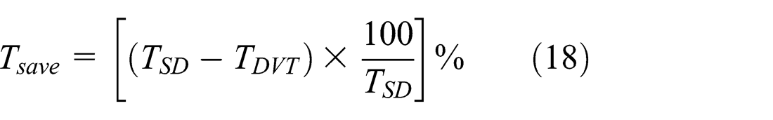
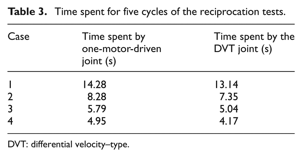
For the reciprocation ability, as shown in Figure 5, the DVT joint has no dead time interval, but the SD joint must stop and change the operating direction to perform reciprocation. To prove this idea, a series of experiments are tested. In these tests, one of the motor sets of the DVT joint is locked by a mechanical blocker to simulate the behavior of the SD joint. The other motor is driven to rotate the DVT joint from 45° to 135° with a positive speed and then reversing with a negative speed for five cycles. Also, the DVT joint is laid horizontally, so that the gravity effect can be ignored. For the reciprocation ability of the DVT joint, the DVT joint rotates from 45° to 135° with the desired speeds as listed in Table 2. The DVT joint is reversed from 135° to 45° by exchanging the speeds of the two motors. The time histories of the joint angle in these tests are plotted in Figure 12, and the results are listed in Table 3. From these results, an index, time saving percentage (
Motor set speeds of the reciprocation tests.

DVT: differential velocity–type.
Time spent for five cycles of the reciprocation tests.
DVT: differential velocity–type.

Time histories of the reciprocation tests: (a) case 1, (b) case 2, (c) case 3, and (d) case 4.
where
The percentage of time saving is further plotted as shown in Figure 13. Figure 13 shows that the DVT joint saves 7.9%−15.7% time compared with the SD joint. It is because the motor has to spend more time to stop and reverse at high speed than at low speed under the same acceleration or deceleration capability. There are two motors in the DVT joint to achieve the accelerating or decelerating task simultaneously. So, the effect is more obvious at high speed. So, it can be concluded that the DVT joint has better reciprocation ability than the SD joint, especially at high-speed condition.

Time saving percentage of the DVT joint versus different joint speeds.
Delta robot with the DVT joints
Delta robots are used in food industry widely since the feature of high-speed reciprocation. A soft delta robot was developed to manipulate onions and artichokes with the customized vacuum suction cup. 15 But it is not popular to implement on other processes, for example, inserting parts into metal materials. In order to demonstrate the features of the DVT joint on compliance and high-speed reciprocation, a new type of delta robot constructed with the DVT joints, called as DVT delta robot, is designed to perform the flexible assembly as shown in Figure 14. To reduce the rotating inertia, a new type of the DVT joint is also designed as shown in Figure 15. Low-cost DC motors are used in the new driving sets. The specification and parameters of the motor and the encoder where some are provided by the manufacturer and some are identified from experiments are listed in Table 4. Aluminum alloy is used to construct most parts of the delta robot, and the carbon-fiber rods are used as the lower limbs for lightweight design. The maximum payload of the DVT delta robot is up to 0.7 kg.

Prototype of DVT delta robot.
Differential velocity–type driving module.
Specification and parameters of the motor and encoder used for the DVT delta robot.

DVT: differential velocity–type; EMF: electromotive force.
In order to control the DVT delta robot, the kinematics is necessary to derive first. The coordinates of the DVT delta robot are defined as shown in Figure 16, where

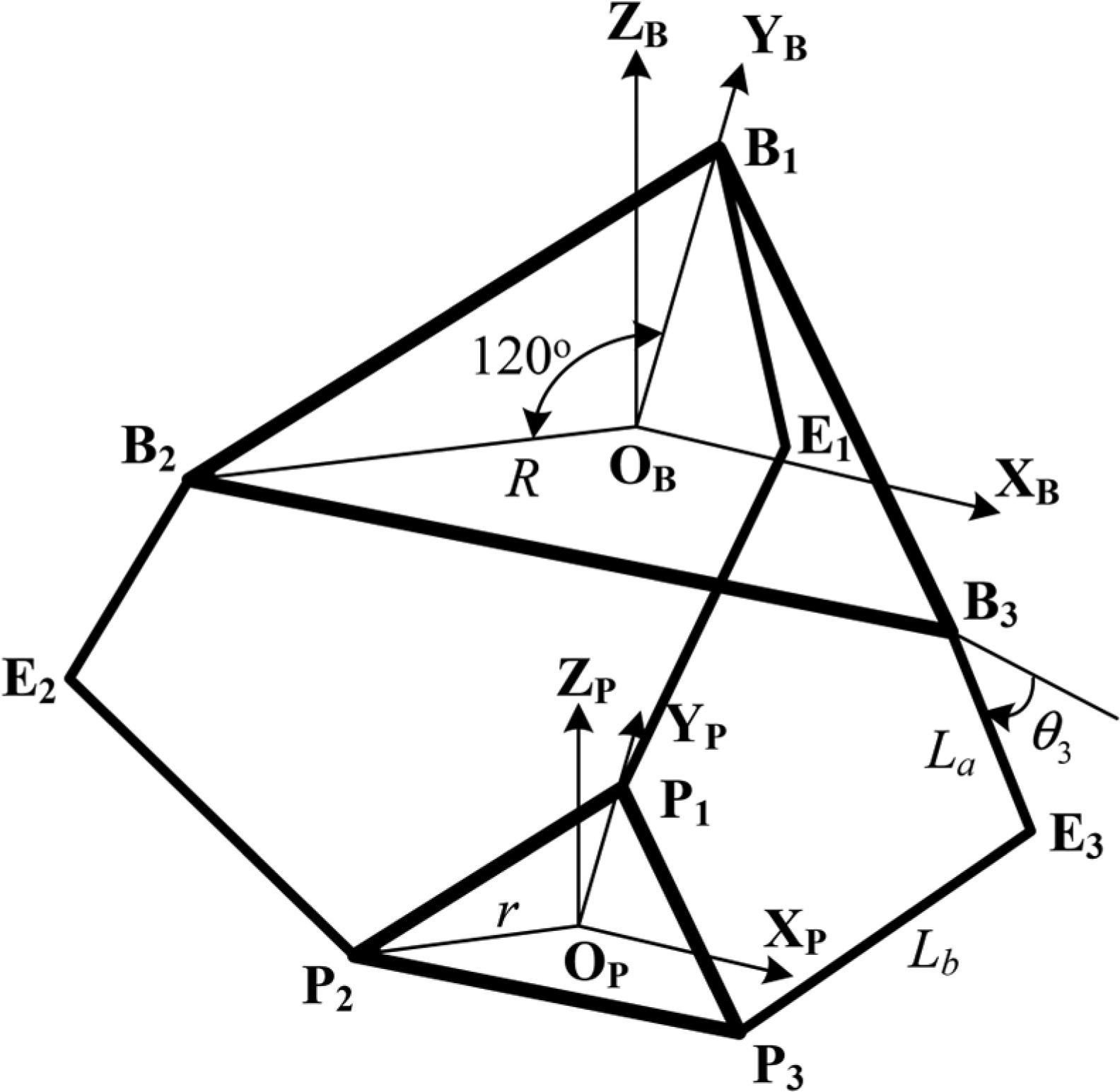
Coordinates of the DVT delta robot.
where
Also, the working space should be analyzed considering the interference angle of the connection joint. In this design, the interference angle is 45°. Thus, the working space can be solved by iteration method with the geometric constraints of the interference angle of the connection joint. The working space is illustrated as shown in Figure 17 with the parameters of

Working space of the DVT delta robot.
The control architecture of the DVT delta robot is shown in Figure 18. Two types of micro-controller are used in this study. One is AVR which dominates the trajectory planning, inverse kinematics, the joint command generation, and the stiffness regulation. The other is dsPIC which is used to control the velocity of motors of each DVT driving module. The velocity control algorithm of each DVT driving module is shown in Figure 19. One of the motors in the DVT driving module is chosen to be the base motor whose velocity is set according to the stiffness requirement. For the stiffness of the DVT driving module, it is varied with the velocity of the base motor.
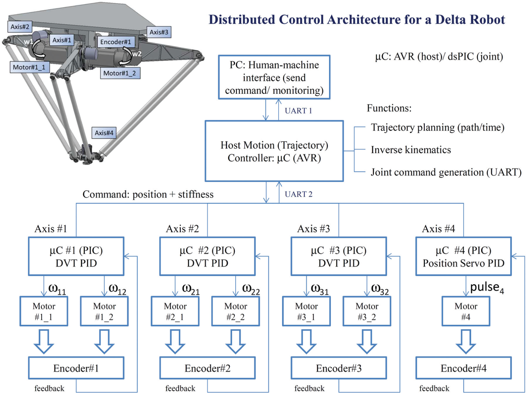
Control architecture of the DVT delta robot.
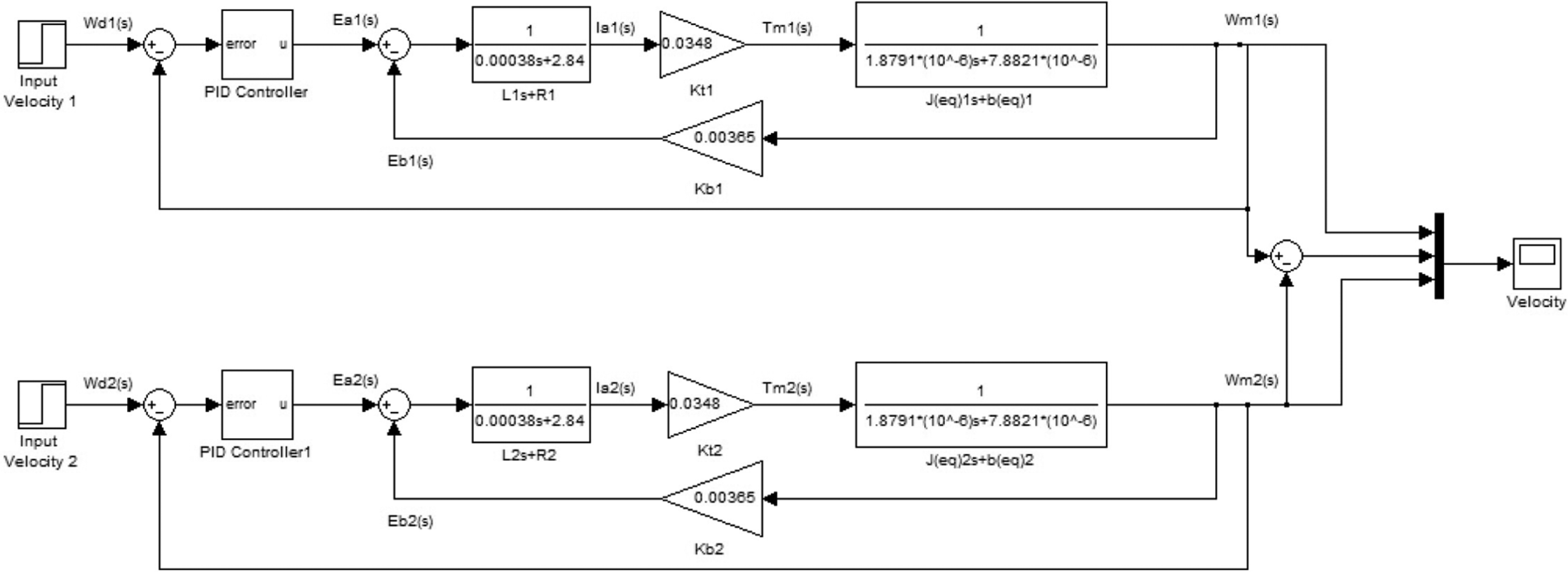
Simulation velocity control algorithm of the DVT driving module. L1 is the armature inductance of motor 1, R1 is the armature resistance of motor 1, Kt1 is the torque constant of motor 1, J(eq)1 is the equivalent moment of inertia of motor 1, b(eq)1 is the equivalent viscosity of motor 1, and kb1 is the back EMF constant of motor 1; the definitions of the parameters of motor 2 are the same.
Furthermore, the control gain effects on the velocity response are studied as shown in Figure 20. The results show that different control gains do not affect the velocity response obviously. When an external force is applied on the output shaft, the control gain affects the velocity response violently as shown in Figure 21. The results show that high P gain restrains the variation of velocity. In other words, high P gain makes the driving module stiffer. Therefore, the compliance of the driving module is not only designed with base velocity but also with the control gains.
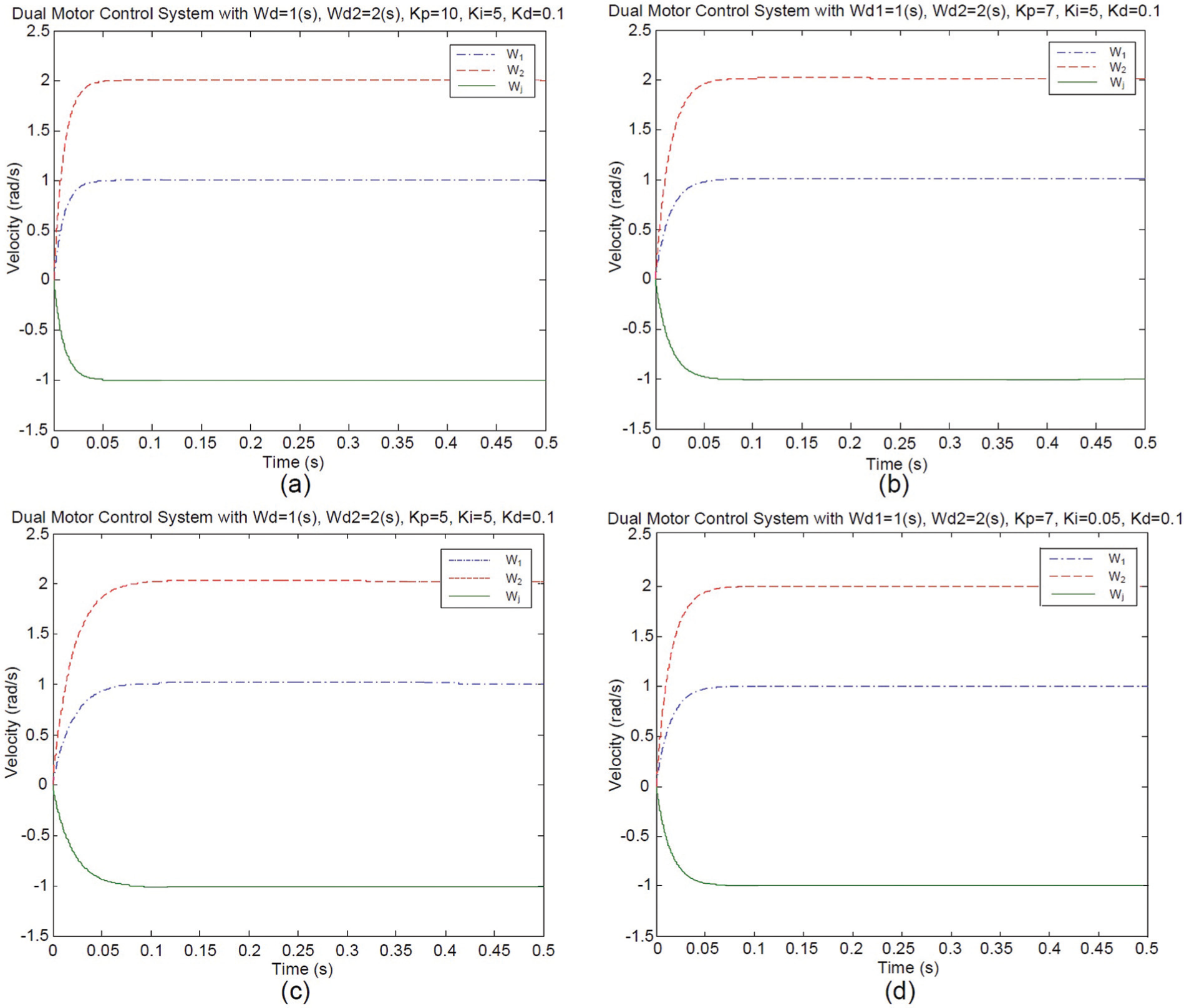
Control gain effects on velocity response: (a) dual motor control system with Wd = 1 (s), Wd2 = 2 (s), Kp = 10, Ki = 5, and Kd = 0.1; (b) dual motor control system with Wd1 = 1 (s), Wd2 = 2 (s), Kp = 7, Ki = 5, and Kd = 0.1; (c) dual motor control system with Wd = 1 (s), Wd2 = 2 (s), Kp = 5, Ki = 5, and Kd = 0.1; and (d) dual motor control system with Wd1 = 1 (s), Wd2 = 2 (s), Kp = 7, Ki = 0.05, and Kd = 0.1.

Control gain effects on velocity response with external force: (a) with external force = 0.05 N m, Kp = 0.1, Ki = 10, and Kd = 0.003; (b) with external force = 0.05 N m, Kp = 0.7, Ki = 10, and Kd = 0.003; and (c) with external force = 0.05 N m, Kp = 1.2, Ki = 10, and Kd = 0.003.
For practical application, such as pick-and-place, the vibration is sometime accompanied by high-speed reciprocation. To verify the capability of the DVT delta robot, a test standard for industrial robot is used in this study. The mobility of the DVT delta robot is tested with a trajectory where the end-effector is moving 25 mm upward, moving 200 mm horizontally, moving 25 mm downward, and then moving back along the coming trajectory. In the moving progress, the vibration will be measured by a three-axis accelerometer. Figure 22 shows the time history of the vibration of the end-effector with different cycle times of 0.3 s, and the maximum vibrations are listed in Table 5. For industrial applications, the highest standard of vibration of the end-effector is less than 0.5 G. In Figure 22, the maximum vibration with cycle time is obviously unacceptable. The vibration with cycle times higher than 0.5 s would be acceptable for the industrial application.

Time history of the vibration of the end-effector with different cycle times: (a) 0.3 s, (b) 0.5 s, (c) 1.0 s, and (d) 2.0 s.
Vibration test of the end-effector.

To demonstrate the capability of the flexible assembly, a set of standard workpieces made by Misumi Corporation is used to test. The standard workpieces are the locating pin of the model number R-FNNA5-P10-B15-L5 and the bushing of the model number JBHN10-6. The geometric tolerance of these two workpieces are −0.005 to −0.014 mm and +0.005 to +0.014 mm, respectively. The assembly tolerance is 0.01–0.028 mm. The DVT delta robot holds the locating pin to put in the bushing as shown in Figure 23. The position histories of the end-effector are calculated from the information of the absolute encoders. Figure 24 shows the z-direction displacement of the center of the end-effector. It can be found that there are obvious forces generated when the pin is taken out from the bushing in the z-direction, and overshot occurred in the z-direction because of the compliance of the DVT driving modules.

Experimental photograph of the flexible assembly.

Displacement of the center of the end-effector.
Conclusion
In this study, the characteristics of the DVT joint in terms of using a differential velocity scheme are verified. The speed/output torque of a DVT joint is modulated by differentiating the speed commands of a pair of actuators. Moreover, a delta-type robot is designed to implement the feature of the DVT joint. Three conclusions are made as follows: (1) for the differential velocity mode, the stiffness of the DVT joint can be controlled in the range of 0.06–7 N m by changing the speeds of both the motors; (2) due to the reciprocation ability, the DVT joint can save 7.9%−15.7% time than the SD joint when performing five cycles of reciprocation; and (3) a new delta-type robot is designed to implement the compliant feature of the DVT joint. The experimental results showed that the flexible assembly operations within a 0.028-mm tolerance can be achieved by the new design. From the results, the DVT delta robot can be applied to high-precision mechanical assembly operations and some tasks which need high compliance. In the future work, the high-speed response of the DVT-based delta-type robot will be studied further.
Footnotes
Acknowledgements
The authors are grateful to the anonymous referees for their helpful comments and suggestions to improve the presentation of this article.
Academic Editor: Seiichiro Katsura
Declaration of conflicting interests
The author(s) declared no potential conflicts of interest with respect to the research, authorship, and/or publication of this article.
Funding
The author(s) disclosed receipt of the following financial support for the research, authorship, and/or publication of this article: This work was financially supported by the Department of Industrial Technology, Ministry of Economy, Taiwan, R.O.C.