
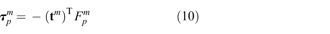
Abstract
We present the development, modeling, and control of a three-degree-of-freedom compliantly actuated leg called the eLeg, which employs both series- and parallel-elastic actuation as well as a bio-inspired biarticular tendon. The leg can be reconfigured to use three distinct actuation configurations, to directly compare with a state-of-the-art series-elastic actuation scheme. Critical actuation design parameters are derived through optimization. A rigorous modeling approach is presented using the concept of power flows, which are also used to demonstrate the ability to transfer mechanical power between ankle and knee joints using the biarticular tendon. The design principles and control strategies were verified both in simulation and experiment. Notably, the experimental data demonstrate significant improvements of 65–75% in electrical energy consumption compared with a state-of-the-art series-elastic actuator configuration.
1. Introduction
Considerable advances have been made in the field of robotic actuation over the past two decades. At the heart of this advance has been the increased use of compliance, both in series between actuator drives and their outputs, as well as in parallel to actuation drives. Similar to biological systems, the use of non-stiff actuation allows for energy storage and release during different stages of the motion.
The most widely adopted concept has been series compliance, known as series-elastic actuation, pioneered by Pratt and Williamson (1995). It has been well demonstrated that this concept can improve energy efficiency (Paluska and Herr, 2006; Velasco et al., 2013), torque control performance and stability (Calanca et al., 2015; Robinson et al., 1999; Roozing et al., 2017; Vallery et al., 2008), physical robustness, and interaction safety. In field robotics, where environments are uncertain and unexpected collisions common, the physical robustness and interaction safety of series-elastic actuators (SEAs) is highly beneficial (Hutter et al., 2016; Negrello et al., 2015; Paine et al., 2015).
The addition of compliant elements in parallel to main actuation branches, known as parallel-elastic actuation, has seen less adoption than series-elastic actuation. However, its benefits have been demonstrated repeatedly, in test bench setups (Haeufle et al., 2012; Mathijssen et al., 2015, 2016; Mettin et al., 2010; Plooij et al., 2016), hopping robots (Liu et al., 2015), bipedal walkers (Mazumdar et al., 2016; Yang et al., 2008), and humanoids (Shirata et al., 2007). Other fields of application are exoskeletons (Toxiri et al., 2018) and prostheses, where parallel compliance has been utilized in prosthetic ankles (Au et al., 2009; Flynn, 2015; Jimenez-Fabian et al., 2017; Realmuto et al., 2015) and knees (Pfeifer et al., 2015; Rouse et al., 2013), to reduce the motor torque required to produce the desired deflection-torque profiles. A common problem with parallel compliance is that during some phases of the motion the parallel element’s generated torque is not well aligned with the desired torque. The result can be that the main actuation drive has to work against the parallel compliance in order to obtain the desired joint torque. To solve this issue, many works employ unidirectional elements (Au et al., 2009; Jimenez-Fabian et al., 2017; Mazumdar et al., 2016; Mettin et al., 2010; Realmuto et al., 2015), clutches/switches (Haeufle et al., 2012; Liu et al., 2015; Plooij et al., 2016; Rouse et al., 2013), or secondary pretension motors (Mathijssen et al., 2015; Roozing et al., 2016, 2015), to engage and disengage parallel elements at desired instants.
Some works have compared SEAs and parallel-elastic actuators (PEAs), mainly in torque and power requirements. Cyclic hoppers were considered by Velasco et al. (2013) and Yesilevskiy et al. (2015), and exoskeleton actuation was considered by Wang et al. (2011). Grimmer et al. (2012) showed that combining SEA+PEA can yield further benefits. In general, the varied results suggest that whether SEAs or PEAs yield the largest benefit in terms of energy consumption depends on the application (Verstraten, 2016). Specifically, exploiting the use of motions that coincide with the system’s natural frequency appears to be suitable for the energy-efficient application of SEAs, as evidenced by the results on hoppers. However, this approach inherently limits the energy-efficient operation to those frequencies. On the other hand, PEAs are well suited for potential energy balancing of systems, such as those under gravitational load (Roozing et al., 2016, 2015).
Biarticular muscles commonly found in biological systems span multiple joints. Examples in humans are the rectus femoris and hamstrings, spanning the hip and knee joints as an antagonistic pair, the biceps, and the gastrocnemius muscle, spanning the knee and ankle joints. In biomechanics such muscles have been identified to transfer mechanical power between joints (Prilutsky and Zatsiorsky, 1994; Schenau, 1989). This principle has been used as a basis for biarticulated robotic actuators. Klein and Lewis (2009) experimentally demonstrated the transfer of mechanical power between joints in a leg that models all nine major sagittal muscle groups in the human lower limb. This was also demonstrated in a foot–ankle prosthesis in Flynn (2015). Iida et al. (2008) and Niiyama et al. (2007) used biarticulation in walking and jumping, respectively. Salvucci et al. (2014) showed how biarticulation can improve the end-effector force ellipsoid. The recently introduced compliant bipedal walker of Loeffl et al. (2016) also includes a biarticular tendon spanning ankle and knee.
In Roozing et al. (2015) the authors proposed an alternative mechanical structure which combines a high-power SEA with a parallel energy storage branch. Contrary to most PEA designs, the secondary branch is not passive but employs a secondary motor that allows to adjust the pretension. Using a distributed controller integrating both branches for energy efficient operation, the authors experimentally verified its effectiveness on a 1-DoF leg, demonstrating a 65% reduction in electrical power consumption when compared with conventional SEAs.
Based on generalizations of the concept, design optimization, and control in Roozing et al. (2016), the recent works Roozing et al. (2018) and Ren et al. (2018) presented the novel design of the eLeg: a three-degree-of-freedom (3-DoF) leg with series and parallel compliant actuation, both with monoarticulated and biarticulated actuation configurations. Figure 1 shows the prototype in its monoarticulated configuration. Preliminary experiments on the realized prototype demonstrated its potential, with significant energy-efficiency improvements of up to 60%, along with significantly reduced torque requirements on the main actuators. This work builds upon these previous works, significantly contributing by:
analyzing the results of the design optimization procedure in depth, indicating the relative strengths of monoarticulated and biarticulated configurations; most notably, we show the beneficial effects of coupling introduced by the biarticular tendon;
presenting extensive simulations of the three actuation configurations that show the baseline comparative performance of the different actuation configurations; furthermore, they provide a basis to choose control gain of a recently developed gradient-descent-based control method (Roozing, 2018), governing the adjustment of the parallel tendons; we leverage a recently proposed modeling approach using the concept of power ports, used to model the energy flow between actuators and robot;
application of the gradient-descent-based control method to an updated hardware prototype, and presenting new experimental data that demonstrate further energy-efficiency improvement over previous results.
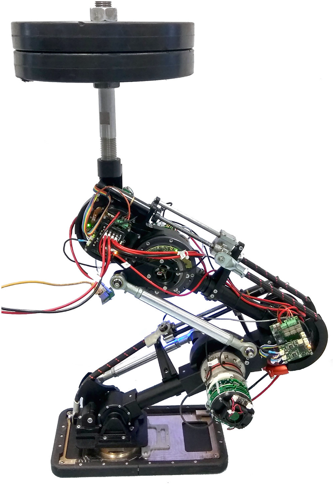
The 3-DoF eLeg prototype in monoarticulated configuration.
This paper is structured as follows. Section 2 outlines the previously mentioned series–parallel actuation concept, followed by the chosen actuation configurations and realized 3-DoF leg design in Section 3. Section 4 elaborates on the modular modeling of both leg and actuators. Section 5 discusses actuation design optimization and applies it to the proposed design, followed by strategies for both leg- and actuator-level control in Section 6. Simulation and experimental studies are presented and data are analyzed in Sections 7 and 8. Finally, Section 9 concludes the work and suggests future directions.
2. Series and parallel compliant actuation
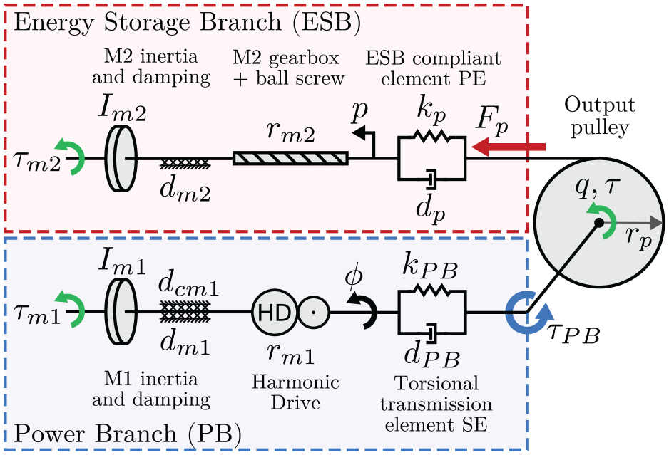
The main components of our series–parallel actuation concept are shown in Figure 2. It consists of two parallel compliant actuation branches, with very different stiffness and power properties. Hence, we refer to this concept as asymmetric compliant actuation (ACA) (Roozing et al., 2016, 2015).
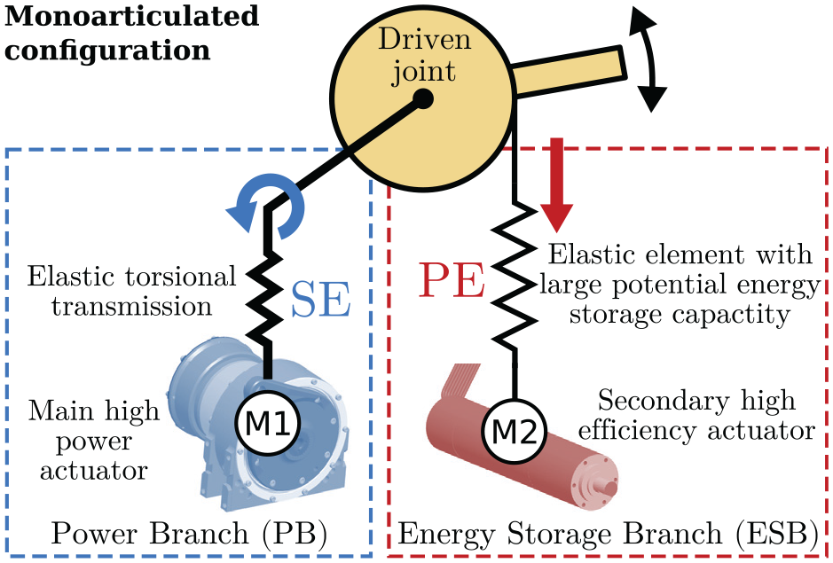
The series–parallel actuation concept we refer to as asymmetric compliant actuation (ACA), shown in monoarticulated configuration.
The first branch, referred to as the power branch (PB), is a rotary SEA consisting of a high-power electric motor M1 in series with an elastic element SE. The second branch, referred to as the energy storage branch (ESB), comprises a highly efficient lower-power motor M2 with high reduction linear transmission. In the monoarticulated configuration shown in Figure 2, motor M2 is coupled to the driven joint through a linear unidirectional series-elastic element PE and pulley. The elastic element PE differs from SE in its significantly lower stiffness and much larger energy storage capacity.
Figure 3 shows the ACA concept in biarticulated configuration, where the ESB tendon spans a free pulley on a second (denoted as spanned) joint before driving the first. In this configuration the elongation of elastic element PE becomes a function of the configuration of both joints, and the ESB provides torque to both joints. Selection of the pulley radii ratio and stiffness value allows to shape the torque profile as a function of both joint configurations and pretension position of motor M2. This fact will be used in the optimization of actuation design parameters of the 3-DoF leg in Section 5. The right-hand side of Figure 3 shows the human gastrocnemius muscle, which is an example of biarticulation in the musculoskeletal system, spanning the ankle and knee joints. 1
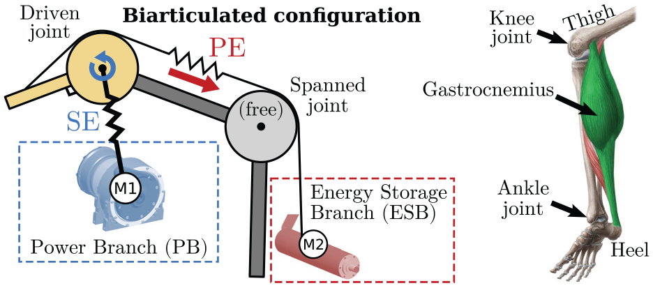
Left: ACA, shown in biarticulated configuration. Right: Human gastrocnemius muscle, spanning ankle, and knee joints.
3. Semi-anthropomorphic leg design
For the design of the 3-DoF leg presented in this work inspiration was taken from the human lower limb. To achieve this, the dimensions and mass distribution of the human limb were investigated, and compared with those of existing humanoid designs. Target specifications for dimensions and segment mass were set as given in Table 1. We opted for a scale slightly under average human size, and aimed for mass not exceeding the human limb. The result is a semi-anthropomorphic design corresponding to a ≈1.50 m humanoid.
Dimensions and mass distribution of the human lower limb (Tözeren, 2000) and design parameters of the robot presented in this article. Note the foot dimension is height, not length.
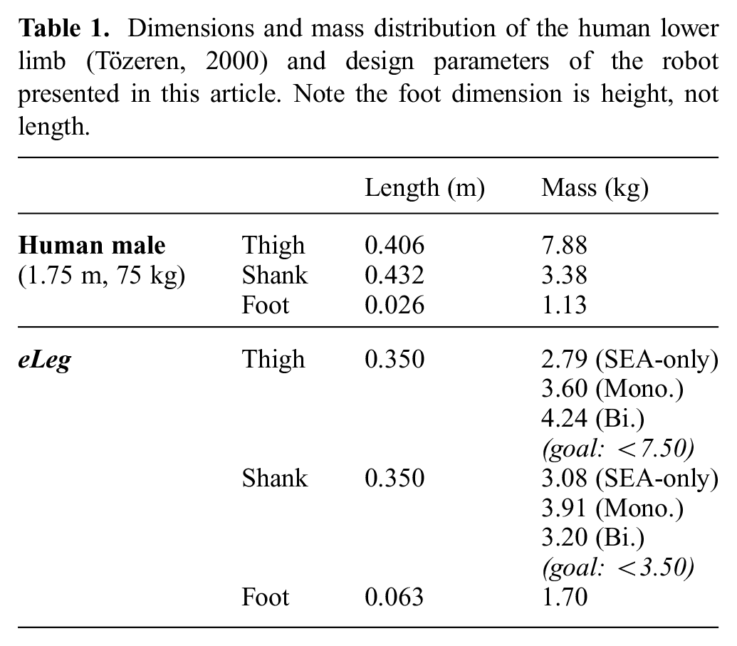
Figure 4 displays the resulting design in CAD for all three actuation configurations, featuring three actuated DoFs: ankle, knee, and hip, respectively. The joints are driven by SEAs, which for the knee and ankle are mounted above the joints and transmit their forces through four bar linkages, and are shown in light blue. This decreases the leg’s moment of inertia with respect to the hip joint. The four-bar linkages are composed of the SEA output flange, the two leg segments that form the driven joint, and a connection rod. The trunk is loaded with a weight representative of a humanoid robot in two-legged stance. The ankle and knee pulleys are integrated structural components, shown in light gray in Figure 4. Three actuation configurations are considered, to show both the potential of our proposed actuation concept as well as investigate the effectiveness of biarticulated actuation arrangements. The leg is designed such that the actuation configurations are rapidly interchangeable, to allow for comparison. As per Figure 4, the three configurations are as follows.
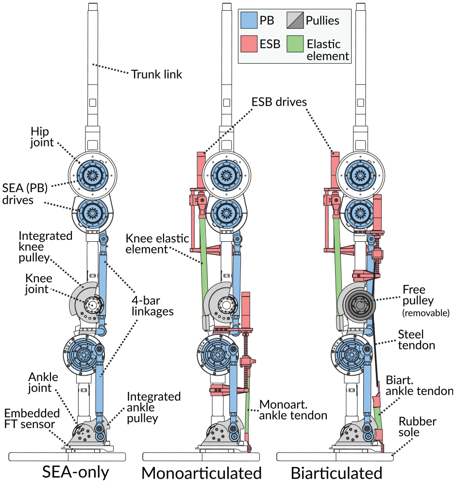
CAD: SEA-only, monoarticulated, and biarticulated configurations, respectively.
As main actuation drives, three identical medium-sized SEAs (Baccelliere et al., 2017) are used, which can provide peak torques up to 127 Nm. Conversely, the ESBs are driven by small high gear ratio motors with ball screws, of which the nuts are instrumented with strain gauges for direct linear force measurement. Figure 1 shows the realized prototype in monoarticulated configuration loaded with 20 kg at the trunk link. For more details, on the hardware implementation, we refer the reader to Roozing et al. (2018) and Ren et al. (2018).
4. Modeling
In this section we proceed with modeling the leg in its various actuation arrangements. For greater flexibility, we opt for a modular approach, modeling the leg and actuators separately, connected through a power port formulation. This allows for quick rearrangement of the actuation configuration.
4. Leg modeling
The leg is modeled consisting of four planar links, with masses

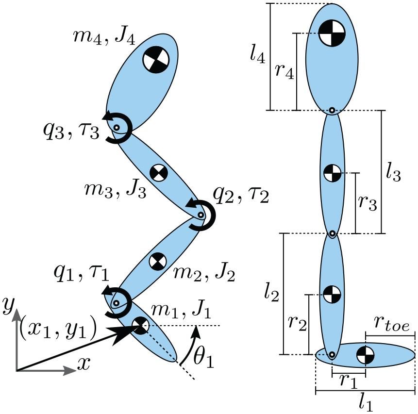
Leg model with floating base. The straight configuration on the right corresponds to
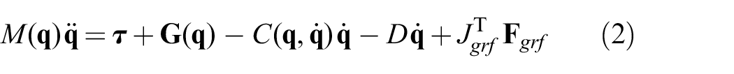
leading to the dynamics
where the damping matrix
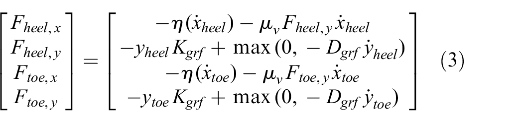
The GRFs in generalized coordinates are given by
where the required parameters are estimated based on the used foot sole material and its thickness, and are given by
4.2. Actuation modeling
We proceed with the modeling of the actuation units that drive each of the leg joints. The model in monoarticulated configuration is shown in Figure 6, driving a single joint with configuration q and applied torque

Actuator model, in monoarticulated configuration.
where
Motor M2 is coupled to the ESB compliance through a gearbox and ball screw with combined ratio
and the torque generated by the ESB on joint i resulting from the linear force

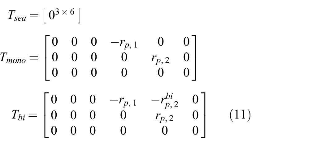
When the actuator is in biarticular configuration as in Figure 3, and we denote the driven joint as joint i and the spanned joint as joint j, then the elongation of the ESB elastic element is given by

and the resulting net torque applied to each joint becomes
where
4.2.1. Power ports
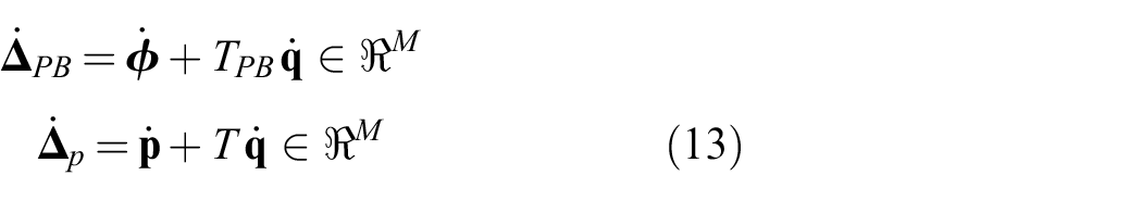
To enable modularity and reconfigurability of the leg and actuator models, we formulate the leg–actuator interconnections using power ports, consisting of sets of power conjugate variables
and similarly maps back the linear force (5) produced by the element to ESB torque
thus completing the formulation of a six-dimensional power port with power conjugate variables
where

and
Conversely, the produced forces are given by
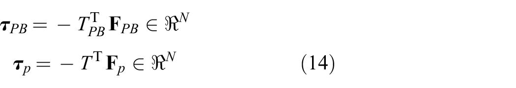
where

The pair
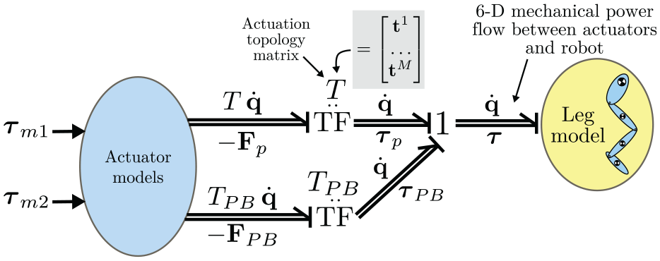
Actuator–leg power flows, shown in Bond graph notation.
We close the discussion on power ports with a brief example of mechanical power transfer from knee to ankle joint using the biarticulated tendon (
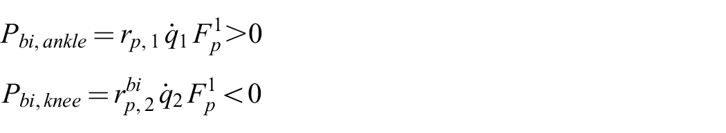
Hence, the biarticulated tendon absorbs power at the knee, and delivers positive power at the ankle joint. By conceptualizing the connection between actuation and rigid-body dynamics as flows of mechanical power, actuation synergies that concern multiple joints are easily recognized, by inspecting the actuation topology matrix T.
4.2.2. Actuator dynamics
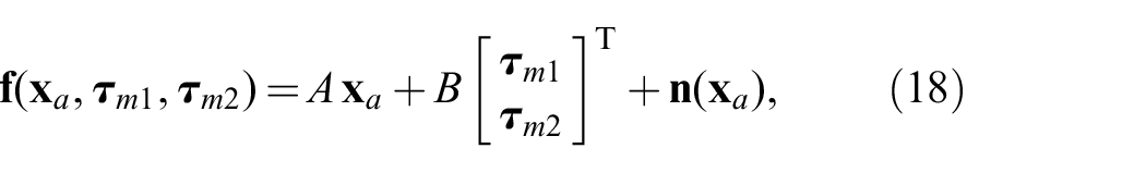
The actuator model inputs, shown in green in Figure 6 for the monoarticulated case, are the two motor torques

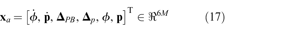
with the state vector
Here
where
where the first two rows can be observed to generate motor rotor forces following from internal damping in the elastic elements, and the third and fourth rows map leg joint velocities to changes in elastic element elongations (cf. (13)). Hence, a change of T and
4.2.3. Electrical dynamics and power
Note that (17) does not include states for motor winding current. As the time constants of the motor electrical dynamics are very small compared with the overall system dynamics, they are neglected for simplicity and simulation speed by neglecting the series inductance.
The resulting model consists of a series connection of voltage source, winding resistance, and gyrator element that interfaces with the mechanical domain. The winding currents

Motor terminal voltage is computed through the series winding resistance
Lastly, the instantaneous power of both motors follows as

The static relations above allow energy consumption to be measured in simulation, and the voltage and current limitations found in the real system to be applied. In experiment, direct measurements of winding currents together with (21) and (22) are used to compute electrical power.
4.3. Losses and efficiency
Considering the terms in (22), we observe that either minimizing current (and, thus, delivered torque) or voltage (that is, motion and/or torque) minimizes the electrical power consumption, with the
Now, consider the ACA concept and model shown in Figures 2 and 6. Assuming the motion to be executed by the robot is given and non-cyclic (i.e., no resonance), the motion of the SEA motor is also given. Hence, minimizing its torque minimizes its energy consumption. This means that if the ESBs can be designed and controlled such that most of the required torque is provided by them, while at the same time the ESB motor is moving as little as possible, the electrical energy efficiency of the entire system is maximized.
Using knowledge of how the required joint torques evolve as function of their positions, one can optimize the stiffness and pulley radii of the parallel ESB tendons to approximate these torques as close as possible. The remainder can then be provided by the SEAs. The next section discusses the optimization procedure and its results in detail.
5. Optimization of design parameters
In an articulated robot, the loading on each joint in general depends on the configuration of all other joints. Hence, optimization of the design parameters needs to simultaneously consider all ESB tendons and a subset of the entire joint workspace. We optimize the ESB design parameters using the method proposed in Roozing et al. (2016). The optimization procedure considers pulley radii
Given the three actuation configurations described in Section 3, the relevant ESB design parameters for both the monoarticulated and biarticulated configurations are shown in Figure 8. While each ESB tendon has three (four for biarticulated) parameters, one of the parameters can be freely chosen, owing to a linear dependency between parameters (e.g., an increase in stiffness is exactly offset by a reduction in pulley ratio and pretension). Hence, the ankle and knee pulleys
ESB parameters for monoarticulated and biarticulated configurations.
5.1. Optimized ESB design parameters
For optimization of the ESB design parameters we choose leg poses as a subset of the joint workspace that keeps the center of pressure (CoP) within the foot support polygon, with the floating base
Optimization joint workspace for
For a visual interpretation of the leg configurations, Figure 9 shows four numbered poses:
deepest straight down squat, where the ankle reaches its joint limit;
a forward leaning posture, with the knee nearly fully extended, and CoP at the edge of the support polygon;
a backward leaning posture, with the hip behind the foot, and CoP at the edge of the support polygon;
straight leg configuration (not shown visually).
The shaded colored leg figures in the right plot of Figure 9 show the leg poses corresponding to the numbered configurations in the left plot.
The optimized ESB design parameters are listed in Table 2. Note that while optimal values of pretension positions
Optimized ESB design parameters. The free (chosen) parameters are indicated by an asterisk.
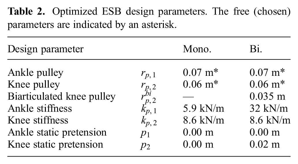
Figure 10 shows the corresponding optimized ESB torque landscapes over
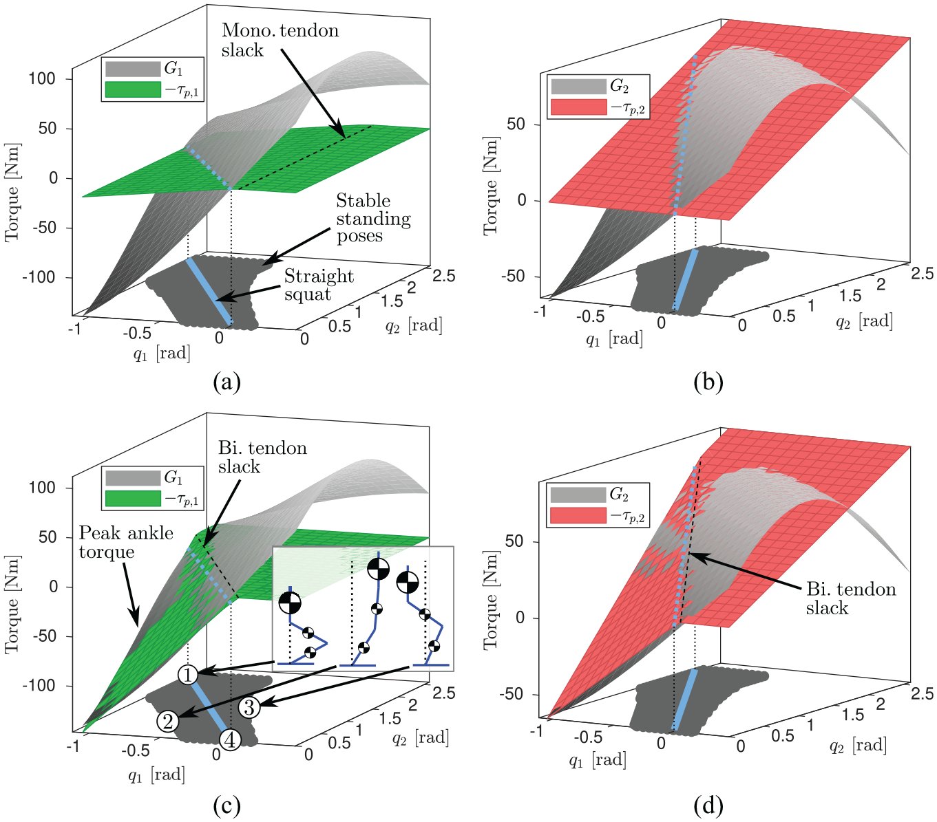
ESB torques for optimized design parameters. Ankle joint shown in green, and knee joint shown in red: (a) monoarticulated ankle joint; (b) monoarticulated knee joint; (c) biarticulated ankle joint; (d) biarticulated knee joint. The
Note the ankle torque in the monoarticulated configuration (Figure 10(a)) is independent of knee angle
As the objective is for the ESB tendons to match the gravitational load as close a possible, one would like the colored planes to match the gray planes as close as possible. Considering the monoarticulated configuration (Figure 10(a) and (b)), accurate torque generation is achieved when close to straight-down squatting configurations (i.e., the blue lines). However, the configuration tends to undercompensate or overcompensate for configurations outside this line (e.g., poses 2 and 3), although generally by less than the absolute torque required, meaning there is still a reduction in torque required from the main actuators. In the biarticulated configuration (Figure 10(c) and (d)), the biarticulated coupling significantly more accurately compensates for loading over the workspace when
A large ankle torque is produced by the biarticulated tendon when the knee extends (
6. Control strategy
For high-level control of the leg, the employed strategy is partly based on Roozing et al. (2016, 2015) in terms of how the desired torque is distributed between the branches; however, control of the parallel ESBs was replaced by a more recent gradient-descent-based control scheme. An overview of the resulting scheme is shown in Figure 11. The joint variables are controlled independently using impedance control with gravity compensation, and the desired generalized torques

where
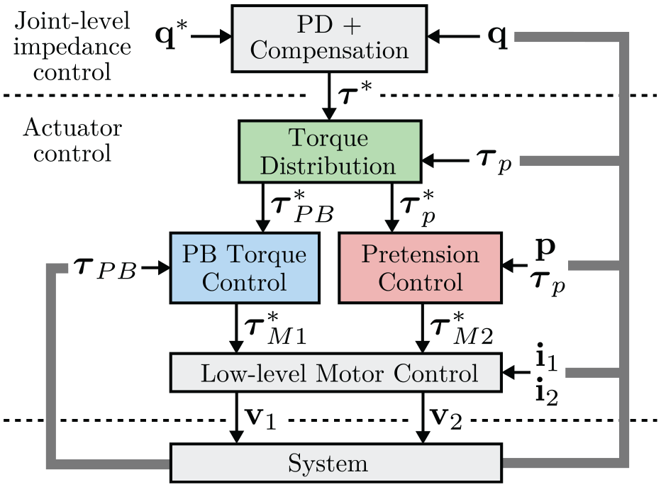
Control architecture.
The actuator control is designed to be agnostic with respect to the high-level control loop. For example, desired joint torques can also result from advanced whole-body control schemes. 5 Indeed, the actuator control strategy tracks the desired joint torques, and attempts to do so in an energy-efficient manner.
6.1. Torque distribution
Owing to their design of high gear ratio and high compliance, together with nonlinearity and hysteresis in the rubber elastic elements, the torque tracking bandwidth of the ESBs is inherently limited by design. Hence, to achieve precise and high-bandwidth torque tracking at the joints, we leverage the excellent torque tracking capabilities of the SEAs. Given desired net joint torques

such that given
6.2. ESB pretension control
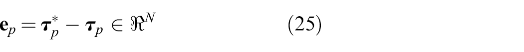
We briefly summarise the gradient-descent-based pretension control strategy developed in Roozing (2018). Owing to the coupling created by multi-articulated tendons, control of the tendons needs to be considered for all tendons simultaneously. Utilizing the actuation topology matrix T, we compute what change in pretension of all tendons leads to the largest reduction in torque tracking error. We start by defining the ESB torque tracking error:
As the objective is to minimize energy consumption of the overall system, and motor power is statically quadratic with generated torque, the squared
where

where
In addition to global asymptotic convergence, the control strategy above has the benefit that it does not require an accurate model of the elongation–torque relations of the elastic elements (which as noted before have nonlinear and hysteric properties), or even a measurement of the elongation of the elements. Only the topology matrix T and approximate stiffness values
7. Simulation study
The effectiveness of the design optimization methods and control strategies were first investigated in simulation. During the development of the platform, a significant number of simulations were performed, to assess viable actuation configurations and support other design decisions, as well as assess performance benefits. We provide some of these results and point out key features.
In many existing works, demonstrations of improved energy efficiency using actuation compliance were the result of carefully chosen resonances or motions close to the natural dynamics of the system. In our case, however, to demonstrate validity and more general applicability of the proposed methods and the resulting leg design, we generate a 140 second motion profile containing a series of different poses, transitions, and a period of cyclic elliptical squatting, shown in Figure 12.
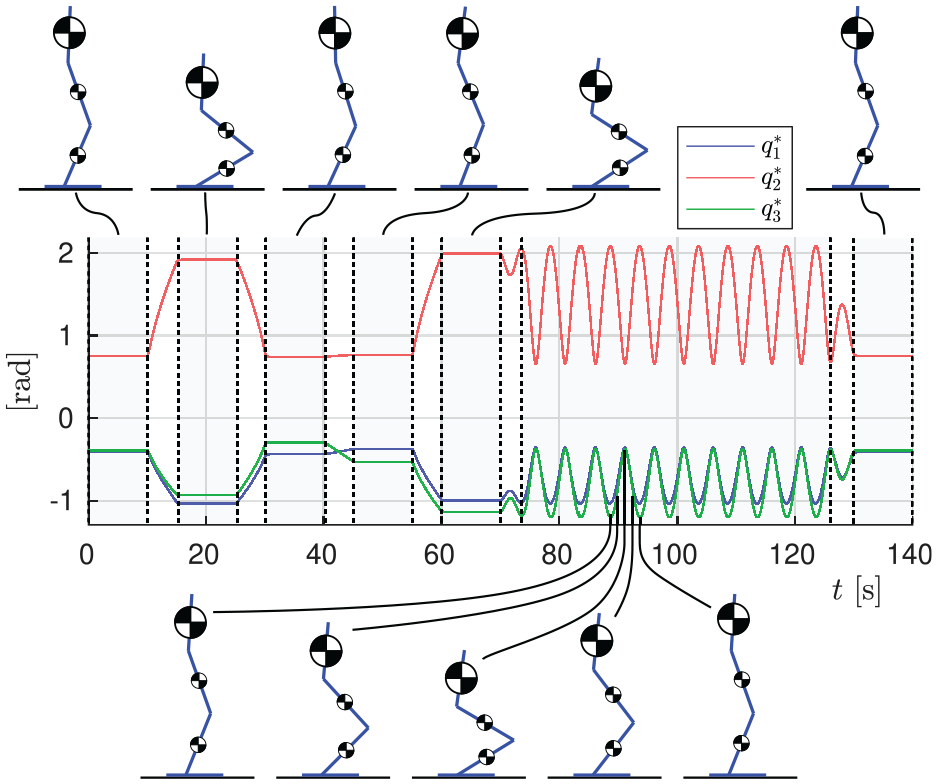
The 140 s motion profile used in simulation and experiment.
In the physical hardware prototype, current control loops are implemented on DSPs with bandwidth of several hundred Hertz. Hence, as explained in Section 4.2, they are omitted in simulation to improve simulation speed, and the electromotive torques are converted into equivalent currents using torque constants. Limitations of the real system, including current and voltage saturation, joint limits, etc., are also implemented in simulation.
7.1. Choosing gradient descent gain
Choice of the gradient descent gain
To approximate the optimal value, we vary
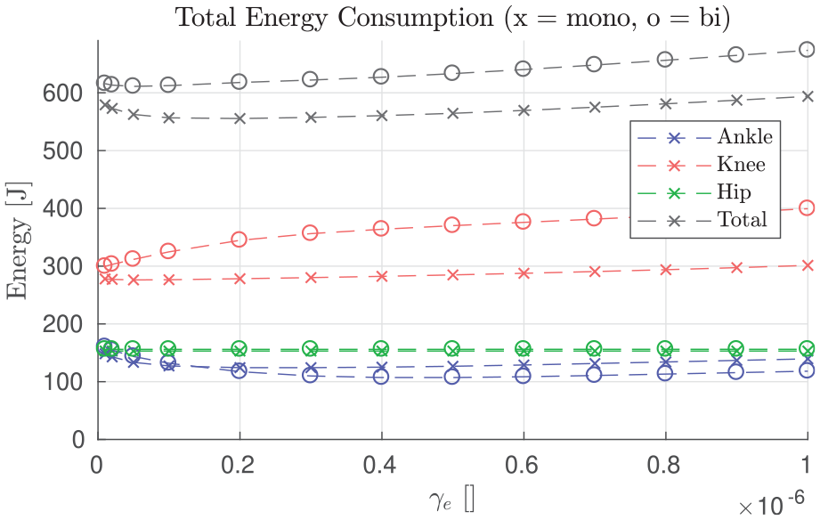
Energy consumption over gradient descent gain
7.2. Results
Simulation results for the motion profile of Figure 12 are shown in Figure 14 for all three configurations. Torques are denoted with subscript representing joint number, and superscript mono and bi denoting contributions from either mono- or biarticular tendons. The joint torque plots (Figure 14(a)–(i)) show that compared with SEA-only, the SEA torque requirements for the ankle and knee are reduced significantly. For example, knee SEA torque was reduced from approximately 35 Nm mean and 55 Nm peak in the SEA-only case (Figure 14(d)), to 0 Nm mean and <5 Nm peak in the monoarticulated and biarticulated cases (Figure 14(e)–(f)). Ankle torque is generally lower but experiences similar reductions.
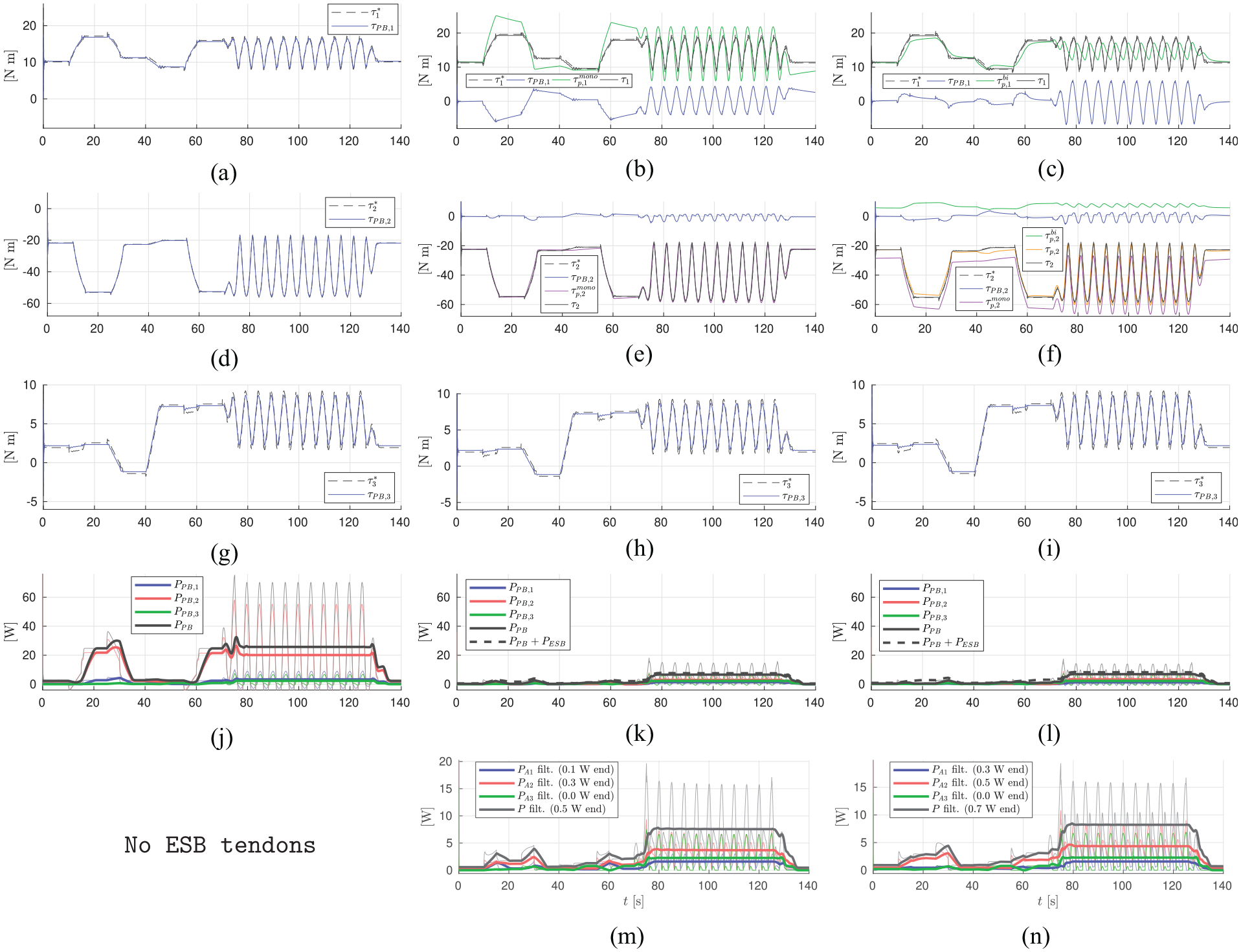
Simulation results. Left column: without ESB (SEA-only); middle column: monoarticulated configuration; right column: biarticulated configuration. Horizontal axes denote time in seconds, and thick (dashed) lines denote 5 second averages of positive (delivered) power. (a) No ESB: ankle (
Correspondingly, electrical energy consumption over 140 s is reduced from 1,965 J (no ESB) to 556 J (mono.) and 620 J (bi.), or improvements of 72% and 68% respectively, for the monoarticulated and biarticulated configurations. Hence, the benefits of the ESB motors and tendons greatly offset the additional mass and secondary motor power consumption. Note the monoarticulated case is slightly more efficient than the biarticulated case; this is because the chosen motion profile keeps the heavy trunk load close to the neutral position above the ankle joint, which favors the monoarticulated case as the coupling between the ankle and knee torque requirements in the configuration space is not as pronounced. Lastly, as shown in Figure 14(j)–(l), peak electrical power is reduced from >70 to <20 W.
Next we analyze the power flow in and out of the biarticular tendon. Figure 15 shows the work done by the tendon on the ankle and knee joints, as well as the net work. Interestingly, relatively little net work is done; nearly all positive work done at one joint is provided by negative work done on the other joint. This indicates the tendon transfers mechanical power from knee to ankle or vice versa. Hence, the biarticular tendon performs a function identical to that of the biological gastrocnemius muscle.
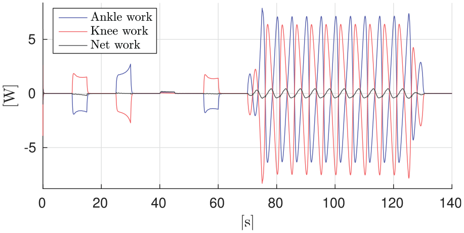
Mechanical power flow of the biarticulated ankle tendon in simulation.
8. Experimental results
Following the promising simulation results, we performed a series of experiments on the hardware prototype to validate the design principles, design optimization, and control strategies in practice. As in simulation, all three actuation configurations are compared: SEA-only (no ESBs), monoarticulated, and biarticulated configuration. We use the same 140 s motion profile as in simulation, and
The experimental results are shown in Figure 17, showing joint tracking (errors), joint torques, power consumption for both branches, and pretension positions. The thick (dashed) lines in Figure 17(p)–(t) denote electrical power trends, averaged over 5 s. Considering these results and comparing the different actuation configurations, a number of phenomena can be observed.
Comparing ankle torques for the monoarticulated and biarticulated configurations (Figure 17(h) and (i)), one observes significantly better alignment between generated ESB torque and desired net ankle torque following from the coupling created by biarticulation, which improves tracking and reduces PB torque required on the ankle joint. At the same time, far smaller pretension adjustments are required from the ESB motor (
As for knee torques, both augmented configurations provide comparable net ESB torques, resulting in the respective PB torques being
Figure 17(p)–(r) show PB and total (PB+ESB) electrical power. Compared with the SEA-only configuration, the electrical power consumption of the system is greatly reduced in both the monoarticulated and biarticulated cases, over the entire period of 140 s. In addition, the required peak power also reduces from 145 to <45 W for both.
The gradient-descent-based controller is effective, adjusting pretension of the ESB tendons such that the required SEA torques are driven to zero (mean) in all cases, despite not using an accurate model of the force-elongation profiles.
Comparing the experimental results with the simulation results presented in Section 7 for each of the actuation configurations, it is clear the overall patterns are replicated. For example, the addition of the ESBs significantly reduces energy consumption by comparable amounts, and brings the required torque contribution from the SEAs to zero mean. However, a number of differences can be observed, that mainly result from shortcomings in the hardware implementation:
The tracking errors that arise from imperfect gravity compensation and finite controlled joint impedance, combined with residual compliance and play 7 in the SEA four-bar mechanisms for ankle and knee, result in some differences between the simulated and experimentally executed motions. This leads to differences in required net joint torque to execute those motions. In particular, in the SEA-only case (left columns in Figures 14 and 17), the knee torque when squatting is approximately 20–30% larger owing to the leg ending up in a deeper squat than intended and the trunk load being further from the knee joint. Furthermore, a brief peak of required torque can be observed as the joint changes direction, which is likely due to the four-bar mechanism generating high (Coulomb) friction when approaching singularity. As power consumption is statically quadratic with torque (see (21) and (22)), these differences increase the knee energy consumption by a factor of 1.5–2 compared with simulation.
The energetic performance increase of the monoarticulated case compared with SEA-only is slightly smaller (65%) than in simulation (72%). This appears to originate from the ankle tendon going into slack during some parts of the motion, creating tracking error spikes. Conversely, the biarticulated case performs better (75%) than expected from simulation (68%), relative to the SEA-only configuration. This is attributed to the experimental motion containing larger horizontal movement of the CoM, which as mentioned before favors the biarticulated configuration.
The power of the ESB motors, shown in 17(s)–(t), is larger than expected from simulation. The main reason is that the optimized linear tendon stiffness values are not replicated exactly by the hardware,
8
which leads to an increase of torque to be provided by the SEAs and larger ESB motor movements, which have a significant affect on the energy consumption. In particular, the knee ESB elastic element can be seen to be too compliant; this causes the ESB motor to make relatively large adjustments to pretension (compare
Analyzing the power flow through the biarticular tendon in experiment in Figure 16, we observe a similar pattern as in simulation. While the magnitude of power is smaller due to lower tension in the tendon, the function of transferring mechanical power between ankle and knee joints is very well replicated.
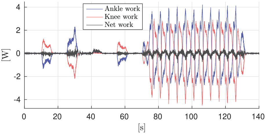
Mechanical power flow of the biarticulated ankle tendon in experiment.
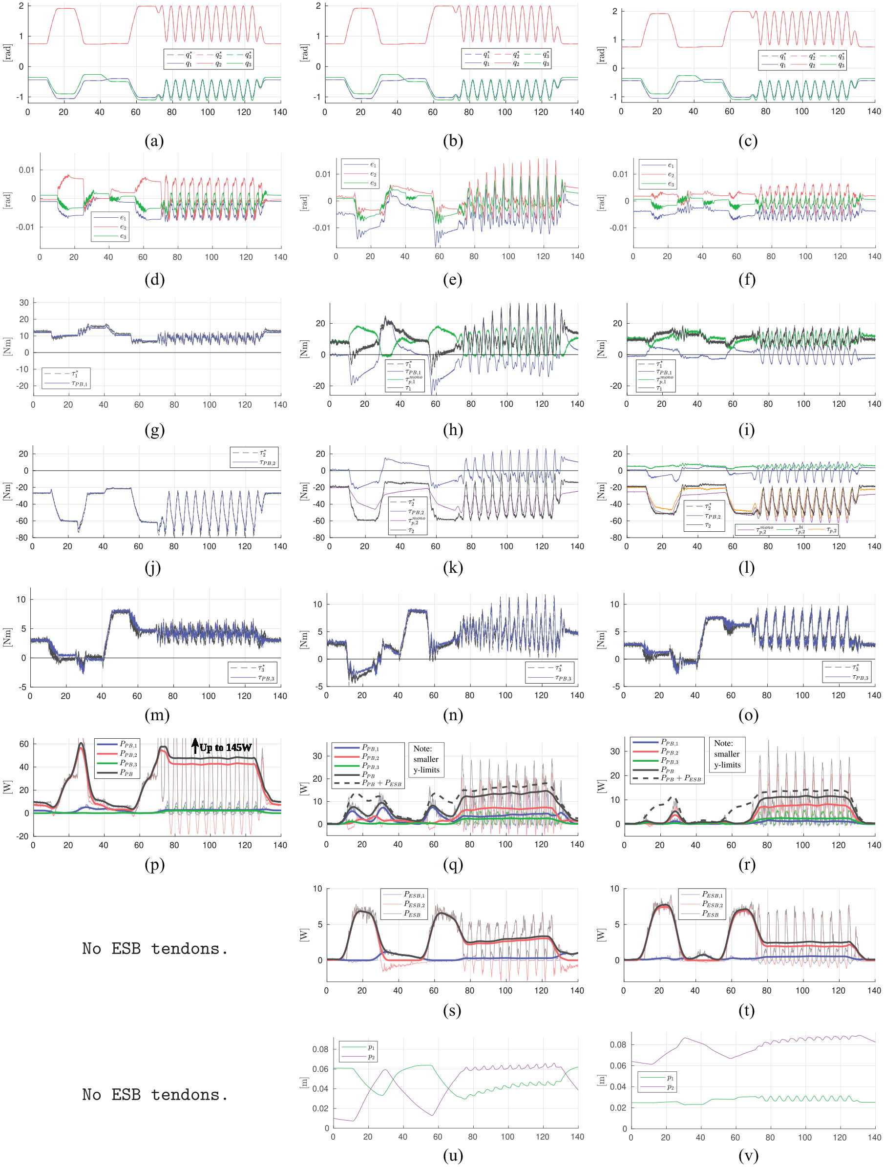
Experimental results. Left column: without ESB (SEA-only), middle column: monoarticulated configuration, right column: biarticulated configuration. Horizontal axes denote time in seconds, and thick (dashed) lines denote 5 second averages of positive (delivered) power. (a) No ESB: joint tracking. (b) Monoarticulated: joint tracking. (c) Biarticulated: joint tracking. (d) No ESB: joint tracking errors. (e) Monoarticulated: joint tracking errors. (f) Biarticulated: joint tracking errors. (g) No ESB: ankle (
8.1. Energetic results
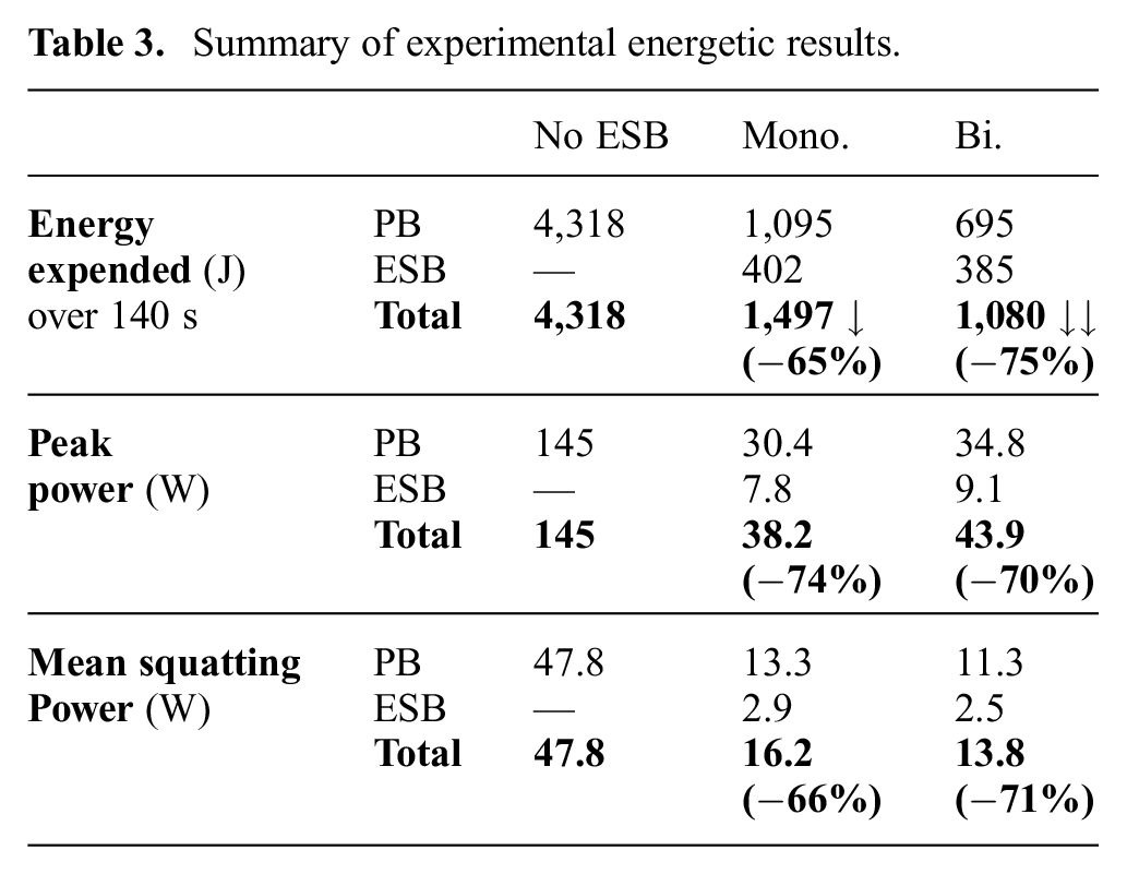
A summary of the energetic results is given in Table 3. The monoarticulated and biarticulated configurations consume 65 % and 75 % less electrical energy, respectively, than the SEA-only configuration over this 140 s period, which is in good agreement with expectations based on the simulation results (which predicted 72 % and 68 % improvements, respectively). Furthermore, peak electrical power requirements are significantly reduced by 74% and 70%, respectively. Lastly, the final rows of Table 3 show the mean power during cyclic squatting from 80 to 120 s, which show 66% and 71% less energy consumption, respectively. In contrast, initial squatting experiments in Roozing et al. (2018) showed 53% and 60% improvement (albeit with a slightly different squatting trajectory requiring less power). The difference is mainly attributed to on-line adjustment of ESB pretension that brings the SEA torques to zero mean.
Summary of experimental energetic results.
8.2. Discussion
We close the experiments section with a discussion on the concept of ESBs and articulated elastic tendons in general. As demonstrated by the experiments, the addition of ESBs significantly reduces the torque requirements and energy consumption of the main SEAs, significantly offsetting their additional mass, energy use, and added complexity. This reduction in requirements allows us to design systems that use smaller, lighter, more efficient main actuators, as well as downscaled power electronics, further improving overall energy efficiency. This is particularly interesting for the more distal joints (e.g., wrists, ankles) of articulated robots, where placing large actuators at those joints significantly increases limb inertia with respect to the body, which is one reason why walking with fully actuated legged robots is such a challenging task.
The current ESB concept focuses on using adjustable pretension for adjustability of the parallel elastic tendons. While undeniably effective, it may be worth exploring variation of the transmission ratio, e.g., by profiled cams and/or actively controllable transmission ratio in the sense of variable stiffness mechanisms.
Biarticulation provides an additional degree of design freedom in the torque generated by such elastic tendons. Our results showed that this additional design freedom allows the torque requirements of the system to be more closely matched. Considering its high usage in legs in nature and results on our biarticular leg configuration, biarticulation appears to be particularly useful for legged robots. Despite only incorporating a single biarticulated tendon in the current prototype, we believe that future articulated robot designs should further incorporate such concepts by considering also the other biarticular muscles seen in biological systems.
Notably, the biological function of mechanical power transfer between joints by the biarticular tendon was replicated both in simulation and experiment. This indicates that biarticular tendons may be used more extensively in robotic systems to provide the explosive dynamic capabilities they have been shown to be a key element for in biological systems. In fact, initial experiments with jumping on the eLeg have shown promising results in this area.
9. Conclusions and future work
This work has presented the development, modeling, and control of a 3-DoF compliantly actuated leg called the eLeg, which employs both series- and parallel-elastic actuation as well as a bio-inspired biarticular tendon. The leg can be reconfigured to use three distinct actuation configurations, which allows a direct comparison of our concepts with a state-of-the-art actuation configuration. An elaborate modeling approach was presented for this unique design, which was the foundation for its design parameter optimization and control strategies.
The design principles and control strategies have been verified both in simulation and experiment. A simulation study has been presented that indicates energy efficiency increases of 72% and 68% for the monoarticular and biarticular configurations, respectively, when compared with a state-of-the-art SEA configuration. Furthermore, peak torque and power requirements were reduced significantly. Similarly, experimental results demonstrate improvements of 65–75% in electrical energy efficiency. Hence, we believe this concept can contribute significantly to the energy autonomy of robots.
However, while the efficiency improvements agree with expectations based on simulation results, differences observed between the simulation and experimental results point to potential directions for future improvement, particularly in the hardware implementation. Specifically, the optimized tendon stiffness values were not replicated exactly in the hardware, leading to a loss in potential performance. Second, the nonlinear behavior of the used rubber-type elastic elements should be accounted for in the design and its optimization. Finally, play and friction in the four-bar linkage transmissions should be improved. In addition to these hardware refinements, future work should focus on further generalization of the concepts of optimized compliant series–parallel and multi-articulated actuation structures, as well as explosive motions and novel control strategies.
Footnotes
Acknowledgements
This work was performed while Wesley Roozing was with Istituto Italiano di Tecnologia.
Funding
The author(s) disclosed receipt of the following financial support for the research, authorship, and/or publication of this article: This work was supported by European Commission projects CENTAURO (grant number 644839) and CogIMon (grant number 644727).