
Abstract
This paper presents a quaternion-based Kalman filter for real-time estimation of the orientation of a quadrotor. Quaternions are used to represent rotation relationship between navigation frame and body frame. Processing of a 3-axis accelerometer using Adaptive-Step Gradient Descent (ASGD) produces a computed quaternion input to the Kalman filter. The step-size in GD is set in direct proportion to the physical orientation rate. Kalman filter combines 3-axis gyroscope and computed quaternion to determine pitch and roll angles. This combination overcomes linearization error of the measurement equations and reduces the calculation cost. 3-axis magnetometer is separated from ASGD to independently calculate yaw angle for Attitude Heading Reference System (AHRS). This AHRS algorithm is able to remove the magnetic distortion impact. Experiments are carried out in the small-size flight controller and the real world flying test shows the proposed AHRS algorithm is adequate for the real-time estimation of the orientation of a quadrotor.
Keywords
Introduction
Orientation estimation is of great importance in a quadrotor design procedure and this key technology can also be found in real-time tracking of human body motion [1] and positioning industrial robot arm [2]. Many orientation and/or position estimation algorithms have been developed with image-based systems [3], magnetic tracking systems [4] and ultrasonic tracking systems [5]. These sourced methods are susceptible to environmental noise and have limited measurement range. Recently, inertial/magnetic sensors have been increasingly used in quadrotors or aerial robotics orientation estimation and do not suffer from measurement range limitations. These small-size modules can be attached on a quadrotor to independently determine orientation without sourced technologies.
Quaternion instead of Euler angles becomes a popular approach to orientation representation because quaternion operates in ℜ4, which is easier to represent any rotations in ℜ3 without singularity problem [6]. In strap-down inertial system, small-size tri-axis MEMS gyroscope and accelerometer are usually mounted on a quadrotor to determine orientation. However, since the accelerometer is unable to sense the rotation about vertical axis, magnetometers are used to measure the local magnetic field vector and allows determination of orientation relative to the vertical. In navigation system, it is called Attitude Heading Reference System (AHRS) [7]. The authors of [8] addressed a Complementary Filter (CF) using inertial and magnetic sensors. Calusdian et al. [9] proposed a quaternion-based adaptive-gain complementary filter. An iterative method, Gradient Descent (GD) algorithm, was presented in [10] and [11] with MARG (Magnetic, Angular Rate, and Gravity) sensors. In CF and GD, gyroscope is used for determining orientation. Accelerometer and magnetometer are able to eliminate the orientation error driven by gyro bias drifts. However, it should be pointed out that these methods do not involve system errors and sensors' measurement noise, thus the estimation accuracy depends on inertial/magnetic sensors.
Kalman Filter (KF) and Extended Kalman Filter (EKF), as a kind of famous optimal estimation methods, have been applied in many fields, especially in spacecraft attitude estimation [12]. Sabatini [13, 14] proposed a standard quaternion-based EKF for determining orientation using 9-DOF (3-axis angular velocity, 3-axis acceleration and 3-axis magnetic field) sensors. In [13], 10 states (4-D quaternions, 3-D acceleration bias and 3-D magnetic field bias) were modeled. The measurement model was linearized by computing the Jacobian matrix. For better estimating the gyro bias drifts without increasing the dimensions of state vectors, gyro was corrected by cubic polynomial temperature curve in [15] and a quaternion-based EKF was presented for AHRS. Recently, some papers [16–18] focus on dealing with the external acceleration or magnetic disturbance, which would disturb the orientation estimation significantly. However, it is noted that the standard EKF must linearize the process models and/or measurement models, which would inevitably induce linearization errors into Kalman filter. Moreover, it is a large computational load for microcontrollers to compute Jacobian matrix.
To avoid linearizing measurement models and reduce computational loads, many approaches have been developed for quaternion-based nonlinear observation. Bach-man et al. [19–22] described an improved quaternion-based Kalman filter for human body tracking. En [19], a Gauss-Newton iteration method was used to preprocess accelerometer and magnetometer to produce quaternions input to Kalman filter. Error quaternions were used in reduced-order Gauss-Newton method in [20] to reduce the dimensions of state vectors. In fact, estimation from vector measurements at a single time, which is known as “single-frame” algorithm, can be described as Wahba's problem [23]. QUaternion ESTimator (QUEST) algorithm, as one of the optimal quaternion “single-frame” algorithms, was implemented for a quaternion-based Kalman filter in [21]. A factored quaternion algorithm, which is computationally more efficient than QUEST about 25%, was also presented in [22]. However, it is seen from the preliminary experimental results in [21, 22] that the estimation from “single-frame” algorithms would produce relatively large errors during the rotational motions. Furthermore, Gauss-Newton method would also require computing inverse matrix of objective error function. Therefore, these methods are not suitable for real-time orientation estimation under fast-moving conditions, especially in a quadrotor.
This paper describes a quaternion-based Kalman filter for AHRS using an Adaptive-Step Gradient Descent (ASGD) algorithm. Quaternions are used to represent orientation of the quadrotor to avoid singularities. Inertial/magnetic sensors are mounted on the center of the quadrotor frame to measure angular velocity, acceleration and local magnetic field vector, respectively. Observation quaternions are produced by gradient descent algorithm with the preprocessing of accelerometer and then inputted to Kalman filter without linearizing observation model. To enhance dynamic tracking characteristic of orientation estimation, an adaptive step-size is set relevant to physical orientation rate. Kalman filter is designed to fuse angular velocity with observation quaternions produced by ASGD. Since the magnetic distortion would affect level attitude (pitch and roll angles) estimation, magnetometer is separated from ASGD to provide heading reference alone, which is called AHRS algorithm. In addition, a small-size flight controller is designed for constructing a quadrotor. Experimental results show that ASGD works well in fast-moving conditions and the AHRS algorithm improves the ability of anti-magnetic distortion. A quadrotor flying test is conducted in real world.
The primary contributions of this paper are:
analysis and deduce ASGD algorithm that improves orientation estimation accuracy under fast-moving conditions;
design a quaternion-based Kalman filter that fuses angular velocity with observation quaternions produced by ASGD;
build a small-size flight controller that uses proposed AHRS algorithm to implement a quadrotor hovering in a real world.
The paper is organized as follows. Section II presents the quaternion-based orientation representation and the Kalman filter process model. Section in describes two approaches to Kalman filter design. Section IV describes the implementation of Kalman filter design with ASGD and an AHRS algorithm is presented in the end. Section V gives a brief description of the small-size flight controller and the quadrotor hardware design. Section VI reports the MATLAB offline testing and real-time orientation estimation of the proposed Kalman filter and the AHRS algorithm. Section VII provides a summary and conclusions.
Quaternion-based Orientation Representation
The orientation of a quadrotor can be described by two coordinate frames. As shown in Figure 1, navigation frame (n frame) is organized by East-North-Up (ENU) definition. Let quadrotor right side as body frame (b frame) xb positive direction, forward as body frame yb positive direction and straight up as body frame zb positive direction. The origin of the b frame and n frame are aligned at point O. Hence, θ, ϕ, ψ represent pitch, roll and yaw angle respectively according to the Euler angles definition. A quaternion

Definition of the navigation frame and the body frame. θ, ϕ, ψ represent the rotation about Xn, Yn and Zn, respectively.

A 3-D vector can be rotated by a quaternion

where v
n
and v
b
are the same vector described in n frame and b frame, respectively;

Rather than a complex rotation equation described by (2), a simpler rotation relationship can be expressed as the Direction Cosine Matrix (DCM) in terms of the quaternion

According to the Z-Y-X aerospace sequence, Euler angles θ, ψ and ϕ can be written as the following identity [24]:

The relationship between the quaternion derivative

where ⊗ represents quaternion multiplication. It is seen that the quaternion
Most quaternion-based Kalman filter process models are established based on (6). In this paper, the Kalman filter process model is depicted in Figure 2. g w denotes the gyroscope measurement noise and will be discussed in details in section IV. In the next section, two Kalman filter designs will be presented.

Kalman filter process model
Two approaches to the Kalman filter design mentioned in section II will be described in this section. State vectors in both two methods are 4-D quaternions, but the measurement equations are different: measurement vectors in the first approach are 6-D vectors (3-axis acceleration and 3-axis magnetic field), which can be given by tri-axis accelerometer and tri-axis magnetometer output. However, 4-D state vectors and 6-D measurement vectors are highly nonlinear, this nonlinear relationships are quite complex that the linearization is needed.
The second approach uses a separate algorithm to produce the computed quaternion by accelerometer. Kalman filter combines the computed quaternion and angular velocity to determine orientation. This method makes the measurement equations become linear, thus the second approach overcomes the ill affect caused by linearization of nonlinear observation model as well as reduces the computational loads of Jacobian matrix.
The First Approach
The first approach is a standard EKF. Many studies choose 7-D (4-D quaternions and 3-D gyroscope output) [19–22] or 6-D (3-D error quaternions and 3-D gyroscope bias drift) [26, 27] vectors as state vectors. In practice, the gyroscope bias drift determined by temperature is relatively small, and the accelerometer and magnetometer are usually utilized to eliminate the gyroscope bias drift. Therefore, 4-D state vectors are

According to (6), state equations can be expressed as

6-D measurement vectors can be directly obtained by the accelerometer and magnetometer output

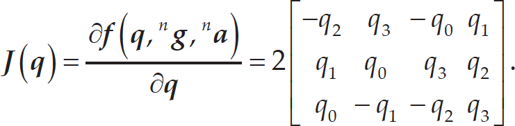
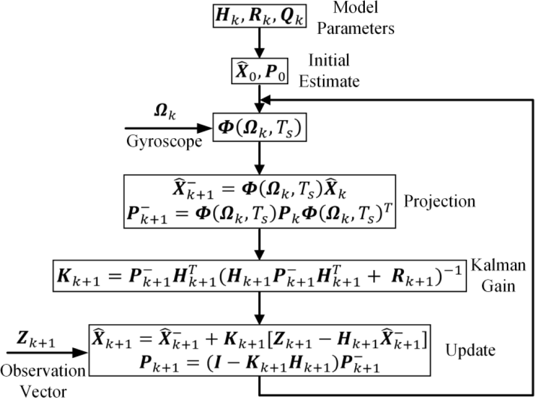
Since the state vectors are 4-D, it is indispensable to linearize the measurement equations and the linearization errors can't be avoided. The establishment of observation model about the first three acceleration components in (9) are relatively simple [15], but the last three magnetic field components are more complex. As for the establishment of magnetic field measurement equations, two popular methods were developed: the first method used the accelerometer and magnetometer to calculate the local magnetic field inclination (dip angle) [13]; the second method directly utilized the local magnetic field distribution table [26]. However, it should be pointed out that the pitch and roll angles are determined both by accelerometer and magnetometer, thus the magnetic distortion would affect level attitude estimation. In this case, some papers used magnetometer only to compute yaw angle [26, 28], The block diagram of the standard EKF is summarized in Figure 3.
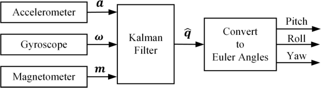
Block diagram of the first approach to Kalman filter design
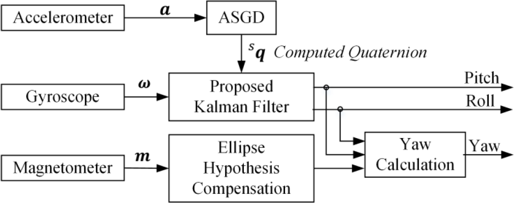
Figure 4 shows the block diagram of the second approach to Kalman filter design. The significant differences between two approaches are the establishment of observation model and the estimation of yaw angle. Gradient Descent (GD) algorithm is adopted here to establish the observation model:

where s q i represents the computed quaternion produced by GD; v i is the noise that is associated with the computed quaternion. One outstanding advantage is that this method removes the need for linearizing observation model. Although Gauss-Newton is a reduced-order of Newton algorithm, it still needs to compute the inverse matrix, which makes it difficult to implement in real-time orientation estimation [19]. GD only uses the first derivative of the objective error function without computing the inverse matrix. It should be noted that the convergence of the GD is subject to the motion rate of the quadrotor. To enhance the dynamic tracking performance of GD, an Adaptive-Step Gradient Descent (ASGD) algorithm is designed based on the physical orientation rate: step-size increases when quadrotor is under fast-moving conditions. On the other hand, step-size deceases when quadrotor rotates in a slow speed.
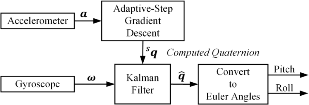
Block diagram of the second approach to Kalman filter design
Attitude Heading Reference System (AHRS) requires an algorithm should estimate attitude as well as heading reference. However, it is noted that the computed quaternion is unable to compute yaw angle since it only incorporates accelerometer. The magnetometer output is separated from ASGD to only estimate yaw angle. A significant advantage of separating magnetometer is that level attitude would not be affected by magnetic distortion. The AHRS algorithm will be presented in section IV.
In this section, the second approach to the Kalman filter design will be discussed in detail. Firstly, the Kalman filter process model will be described, and then deduce the Kalman filter observation model using ASGD. The implementation of AHRS is presented at last.
The Process Model
The state equations described by (8) can be rewritten by

where

ω = [ω x ω y ω z ] T denotes the tri-axis gyroscope output; [ω ×] is a 3 × 3 skew symmetric matrix given by

The next step is to convert continuous-time model represented by (11) into a discrete-time model. Let the system sampling time be T s , then the discrete-time model is given by
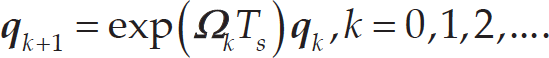
It should be noted that the sampling time T s should be small enough (at least 20ms) that the orientation static error and dynamic error can be reduced [11]. In real-time application, it could be computationally demanding to compute exact values of exp(ω k T s ) in (14). In this paper, Taylor series expansion method is used to expand the exp(ω k T s ) with retaining the first-order and second-order items, that is
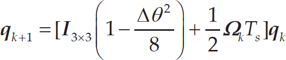
where

In section n, gyroscope bias drift is not considered in Kalman filter process model. But in practice, the gyroscope output can be modeled as

where ω is the angular velocity measured by gyroscope and ω* is the true angular velocity which is unknown;
g
b is the gyroscope bias drift which can be modeled as an exponentially correlated Gaussian random process [29];
g
w is the gyroscope measurement noise with zero mean and covariance matrix

where

where

ASGD is able to produce the computed quaternion input to Kalman filter. Let the normalized gravity vector n g in n frame be

Normalized accelerometer output in b frame is

Then the objective error function is defined by

Many methods have been developed to deal with the objective error function represented by (23), gradient descent algorithm is adopted here as a first-order iterative algorithm. According to the GD definition, the computed quaternion
s

where μ is the step-size and ∇f (

Equations (24) to (26) are the general forms of the gradient descent algorithm only using the accelerometer. Since the GD is a first-order iterative algorithm, (24) should be executed one time at least during an attitude update procedure. One method to improve the orientation estimation accuracy is to utilize second derivative of (23). However, this solution would increase computational loads and is not considered in real-time application. Another alternative method is to find an optimal value of step-size μ to converge faster than quadrotor physical orientation rate. Therefore, μ is associated with the system sampling time T s , physical orientation rate measured by gyroscope ω and a scale factor ²:

where ∼ represents the direct proportion in mathematics; ² is the critical constant parameter which manifest the algorithm's static and dynamic performance. The physical orientation rate can be described by the following expression:

In (27), μ should be a small initial value μ0 when quadrotor is still or under slow-moving conditions. The final adaptive step-size μ is given by

The ideal value of parameter μ0 and ² is that the GD could hold stable attitude in static test and track high speed rotations without too much overshoot. The determination of these two parameters will be given in experimental section. The measurement noise covariance matrix

Noting that the computation of the computed quaternion is based on accelerometer, thus the observation noise v
k
is relevant to the accelerometer measurement noise. In experiments, the computed quaternion was collected to determine
In principle, block diagram of the proposed Kalman filter is summarized in Figure 5. It can be seen from Figure 5 that
Block diagram of the proposed Kalman filter
Since the accelerometer cannot be used to sense the rotation about the vertical axis, the estimated quaternion output by Kalman filter is unable to provide heading reference. Magnetometer is able to measure the local magnetic field, which is incorporated in standard EKF to determine the orientation relative to the vertical. One critical drawback is that pitch and roll angles are significantly affected by magnetic distortion. One method uses two step measurement updates, so the magnetometer output is only used for yaw estimation [26]. However, it would require the need for additional computations as well as some difficulties in the process of implementation. In this subsection, yaw angle estimation is computed combined with the magnetometer output, pitch and roll angles [7]. The block diagram is summarized in Figure 6.
Block diagram of the proposed AHRS algorithm
Before magnetometer is used for yaw estimation, it should be corrected based on ellipse hypothesis [32]. If any one of pitch or roll angle isn't 0° or near to 0°, the magnetometer output

where pitch (θ) and roll (ϕ) are given by (5);
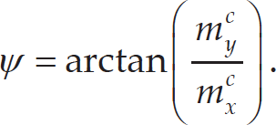
Since the yaw angle is only estimated by magnetometer, pitch and roll angles would not be affected by magnetic distortion.
The quadrotor size is 330 mm length between two diagonal motors, 9.5 cm height and 739 grams weight. In outdoor flying test, it can hover approximately 15 minutes. Structure diagram of the quadrotor hardware design is summarized in Figure 7. Flight controller is placed in the center of the quadrotor to minimize unexpected rotational acceleration. It consists of ST-Microelectronics STM32F405 (ARM Cortex-M4 32-bit CPU with FPU); an IMU module (including MPU6050 embedded tri-axis MEMS gyroscope and tri-axis MEMS accelerometer, tri-axis magnetometer HMC5883L and barometer MS5611); an low-power 0.96 inch OLED display and 4 LEDs (blue, yellow, green and white light). The size of the flight controller is 5 cm × 5 cm × 1.6 cm, which is shown in Figure 8.

Structure diagram of the quadrotor design

Quadrotor flight controller PCB
The MEMS accelerometer embedded in MPU6050 can provide 4 kinds of range with the max ±16g output. It also supports the tap detection, free-fall interrupt and zero motion interrupt. The MEMS gyroscope embedded in MPU6050 can provide 4 kinds of range with the max ±2000 °/s output, which is sufficient to sense the high speed rotation motion. A digitally-programmable low-pass filter is available in MPU6050. The magnetometer HMC5883T has 12 bits A/D conversion and 1∼2° heading resolution. One convenient design is the magnetometer can be treated as the third party device to attach to the auxiliary PC bus with MPU6050. Barometer MS5611 has the measurement range from 10 to 1200 mbar, 24 bits A/D convert and 10 cm high resolution which is used for a quadrotor hovering at a fixed height or position.
USART wireless module is a 433MHz serial communication module, it can be used for the online parameter debug when quadrotor is flying; 2.4GHz remote receiver can receive 6-channel PPM signals from remote control transmitter; Electronic Speed Controller (ESC) and brushless DC (BLDC) motor are the power drive of the quadrotor. Hobbywing skywalker-20A ESC is adopted to drive the Angel A2208 1260KV BLDC. Four 8 × 3.8 propellers (8 inch length, 3.8 inch screw pitch) are installed onto the motor to make the most of the BLDC motor thrust efficiently.
Sensors calibration results

In the next experimental section, flight controller will be used for implementing the proposed AHRS algorithm.
Cross-correlation results and code running time

Inertial and magnetic sensors should be calibrated to eliminate the initial bias error at the system start-up time before they are inputted to Kalman filter. Sensors' data were collected by flight controller and transmitted to MATLAB via a serial communication interface (baud rate: 115 200 bps) while flight controller was still on the desk. The IMU's constant bias and measurement noise standard deviation are shown as Table 1. The gyroscope measurement noise variance Σ
g
2 in Table 1 can be used to compute the process noise covariance matrix
In what follows, all the experimental rotations were carried out by hand. In the first set of experiments, the flight controller was initially placed with its b frame aligned with n frame. The flight controller was rotated 90° about x-axis and then rotated back to level, following a rotation −75° about y-axis and then returned to level in the end. To compare the performance of standard EKF and proposed AHRS, 9-DOF raw sensors data were collected by flight controller and transmitted to MATLAB. Plots are shown in Figure 9. The graphs to the left show the orientation estimated by standard EKF and graphs to the right show the orientation estimated by proposed AHRS. It can be seen that the accuracy performance of pitch and roll angles in two algorithms is similar in general, but a large yaw angle error appears around 12 s due to the magnetic distortion, whereas it is smaller in proposed AHRS.

Orientation estimated by standard EKF (left) and the proposed AHRS algorithm (right)
To manifest the similarity of orientation estimates in two algorithms, cross-correlation of pitch and roll angles is summarized in Figure 10. The top graph shows the cross-correlation of pitch angle and the bottom graph shows the cross-correlation of roll angle. It can be seen that the orientation estimates in two algorithms are highly similar. However, it could be a large computational demanding to calculate 6 × 4 measurement matrix and its inverse matrix in standard EKF. On the other hand, although some extra yaw angle calculations are involved, observation model (10) becomes linear in proposed AHRS, which significantly reduces the matrix manipulation cost. Table 2 shows the cross-correlation results and code running time for 359 times orientation estimates in MATLAB. It is observed from Table 2 that the proposed AHRS has a similar accuracy level and lower calculation cost than standard EKF.
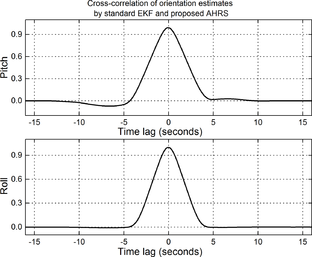
Cross-correlation of orientation estimates by standard EKF and proposed AHRS
In proposed AHRS, yaw angle is only estimated by magnetometer whereas standard EKF combines 9-DOF sensors data. To show the proposed AHRS ability of free-magnetic distortion, an iron-made stick was randomly wobbled near the flight controller to simulate the hard and soft distortion. The flight controller was still on the desk during the whole experiment, therefore pitch and roll angles should be 0°. Pitch/roll angles with magnetic distortion in two approaches are summarized in Figure 11. The graphs to the left show pitch/roll angles estimated by standard EKF with magnetic distortion and the graphs to the right show pitch/roll angles estimated by proposed AHRS with magnetic distortion. It is seen from Figure 11 that large errors appear in standard EKF. On the other hand, the proposed AHRS is not affected by magnetic distortion and can keep near 0° throughout the experiment. Table 3 shows the Root-Mean-Square Error (RMSEe) of pitch and roll angles in two approaches. It is seen that the proposed AHRS removes the ill effect of magnetic distortion.

Orientation estimated by standard EKF with magnetic distortion (left) and the proposed AHRS with magnetic distortion (right)
After offline comparing the performance of standard EKF and proposed AHRS, real-time orientation estimation experiments were conducted in flight controller. In ASGD, initial step-size value μ0> and scale factor ² in (29) are μ0 = 0.01, and ² = 10. In the following set of experiments, the flight controller was rotated as what the first set of experiments did, but twice times. Figure 12 shows the performance of ASGD and the proposed Kalman filter in estimating orientation. The graphs to the left show the orientation estimated by ASGD and the graphs to the right show the orientation estimated by proposed Kalman filter. It can be observed that ASGD is able to relatively correctly estimate pitch angle throughout experimental rotations without some large errors. But during the rotational motions, accelerometer output combines the gravity and external acceleration, therefore, some sudden errors occurred in the estimation of roll angle. On the other hand, the proposed Kalman filter shown in right graphs is able to correctly estimate the pitch angle throughout the experiments.
Figure 13 shows the plots of roll testing. Similar results can be found in this experiment.
Pitch and roll angles estimation with magnetic distortion RMSE

To illustrate the performance of the proposed Kalman filter, the bottom-left graph in Figure 13 is replotted in a zoom-in view for the time period 6–7 s, which is depicted in Figure 14. The solid curve represents the roll estimation by ASGD and the dashed curve is the roll estimation by proposed Kalman filter. Because of the rate sensors in Kalman filter, it is seen that the orientation estimation by proposed Kalman filter is smoother than ASGD.

Orientation estimated by ASGD (left) and the proposed Kalman filter (right)

Orientation estimated by ASGD (left) and the proposed Kalman filter (right)
Adaptive step-size in ASGD is designed to deal with fast-moving conditions to enhance the dynamic characteristic of the proposed Kalman filter. To show the effectiveness of ASGD when quadrotor flight controller is under fast motion, the flight controller was rotated randomly by hand. In comparison to ASGD, a Fixed Step-size Gradient Descent (FSGD) was incorporated. The fixed step-size was 0.04. Experimental results are plotted in Figure 15. The top graph shows the pitch angle estimated by proposed KF, FSGD and ASGD, middle graph shows the roll angle estimated by proposed KF, FSGD and ASGD and bottom graph shows step-size values in ASGD throughout the experiment. In top graph, solid curve represents the pitch angle estimated by proposed KF, dash dot curve is the pitch angle estimated by ASGD and dashed curve is the pitch angle estimated by FSGD. It can be seen that the ASGD is able to track the orientation estimated by proposed KF, but a relatively large lag (approximately 0.2 s) and error (max 25°) occurred in the FSGD. Similar results can be observed in middle graph and the fluctuant step-size curve is shown in bottom graph. To better compare the fast-moving tracking performance of ASGD and FSGD, cross-correlation of ASGD/FSGD and proposed KF is reported in Table 4. It is seen that ASGD is more similar to proposed KF than FSGD.

Zoom-in view of the roll estimation by ASGD (solid curve) and proposed Kalman filter (dashed curve) when roll rotated from −75° to 0°

Pitch angle estimated by proposed KF, FSGD and ASGD (top), roll angle estimated by proposed KF, FSGD and ASGD (middle) and step-size in ASGD (bottom)
Figure 16 shows the outdoor flying test in real world. The proposed AHRS was implemented in quadrotor flight controller, which was attached onto the center place of the quadrotor plastic frame. Cascade PID control law was used for controlling four motors: inner control loop was “rate loop” and outer loop was “angle loop”.
Cross-correlation of ASGD/FSGD and proposed KF


Quadrotor flying test in the real world
This paper presents a quaternion-based Kalman filter for AHRS using an adaptive-step gradient descent algorithm and has been implemented with a quadrotor flight controller. This filter is designed to produce 3-DOF orientation estimation of a quadrotor with mounted inertial/magnetic sensors. Quaternions are used to represent orientation estimation relative to the navigation frame. Accelerometer is preprocessed to produce the computed quaternion input to Kalman filter along with angular velocity. This computed quaternion is computed by ASGD algorithm. The step-size of ASGD is set in direct proportion to the physical orientation rate to improve the fast-moving tracking characteristic of orientation estimation. Although the proposed Kalman filter only output pitch and roll angles, yaw angle is given by magnetometer, which avoids inducing magnetic distortion into level attitude estimation. In experiments, in comparison with the standard EKF, MATLAB offline experiments were conducted using inertial/magnetic sensors data produced by the small-size flight controller. Experimental results show that proposed Kalman filter successfully fused ASGD with angular velocity to produce pitch and roll angles; proposed AHRS algorithm could keep level attitude from being affected by magnetic distortion; ASGD was able to track fast-moving motions with reduced lags and errors. A quadrotor hardware design was described and an outdoor flying test was carried out in real world. This flight experiment demonstrates that the proposed AHRS algorithm works well for estimating orientation of a quadrotor.
Footnotes
8.
This work was, in part, supported by the open fund project of Key Laboratory Program of Metallurgical Equipment and Control, Ministry of Education. ID: 2013B06.