
Abstract
Because of the complementary nature of visual and inertial sensors, the combination of both is able to provide fast and accurate 6 degree-of-freedom state estimation, which is the fundamental requirement for robotic (especially, unmanned aerial vehicle) navigation tasks in Global Positioning System–denied environments. This article presents a computationally efficient visual–inertial fusion algorithm, by separating orientation fusion from the position fusion process. The algorithm is designed to perform 6 degree-of-freedom state estimation, based on a gyroscope, an accelerometer and a monocular visual-based simultaneous localisation and mapping algorithm measurement. It also recovers the visual scale for the monocular visual-based simultaneous localisation and mapping. In particular, the fusion algorithm treats the orientation fusion and position fusion as two separate processes, where the orientation fusion is based on a very efficient gradient descent algorithm, whereas the position fusion is based on a 13-state linear Kalman filter. The elimination of the magnetometer sensor avoids the problem of magnetic distortion, which makes it a power-on-and-go system once the accelerometer is factory calibrated. The resulting algorithm shows a significant computational reduction over the conventional extended Kalman filter, with competitive accuracy. Moreover, the separation between orientation and position fusion processes enables the algorithm to be easily implemented onto two individual hardware elements and thus allows the two fusion processes to be executed concurrently.
Keywords
Introduction
The combination of visual and inertial sensors has been shown to be viable, and the significant performance improvement over a single sensor system has attracted many researchers into the field after the success of SFly project, 1 which enabled the world’s first autonomous unmanned aerial vehicle (UAV) in Global Positioning System–denied environments. 2
In the past 5 years, many prominent research institutions began to develop advanced monocular visual-based simultaneous localisation and mapping (mSLAM) algorithms based on structure from motion (SFM) theory,3–11 which are suitable to modern onboard embedded computers. Moreover, the visual scale problem, which was the main challenge of involving monocular vision into the control loop, has been addressed by fusing onboard inertial measurements (accelerometer and gyroscope), called the visual–inertial navigation system (VINS).12–20
Almost all of the visual–inertial fusion algorithms, to our knowledge, rely on nonlinear Kalman filter (KF) techniques (extended KF, unscented KF, etc.) to process both the orientation and the position measurement in the same process, this results in a large state vector (usually more than 20 states) and a complex nonlinear system model. However, recent advances in computationally efficient inertial measurement unit (IMU) orientation estimation 21 show a competitive accuracy against Kalman-based algorithms by utilising optimisation-based methods. Thus, in this article, a computationally efficient visual–inertial fusion algorithm is proposed by separating the orientation and the position fusion processes, this maintains the same level of accuracy with nonlinear KF approach. The algorithm is designed to perform a 6 degree-of-freedom (DOF) state estimation, based on a gyroscope, an accelerometer and an mSLAM measurement. It also recovers the visual scale for the mSLAM.
The rest of this article is organised as follows: section ‘Algorithm preliminaries’ gives an overview of the visual–inertial fusion algorithm; section ‘Orientation fusion process’ presents the mathematical expression of the orientation filter; and section ‘Position fusion process’ presents the mathematical expression of the position filter. The implementation, test result and conclusion are shown in the last three sections.
Algorithm preliminaries
Coordinate system
The coordinate system used is shown in Figure 1. All the coordinate frames are defined following the right-hand rule. The earth frame
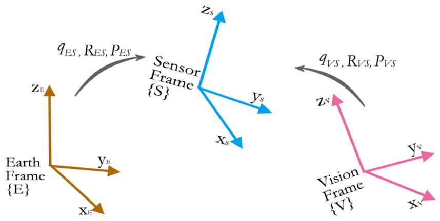
Coordinate system.
The orientation of
Algorithm overview
As shown in Figure 2, the visual–inertial fusion algorithm assumes that rotation

Algorithm overview.
The fusion is separated into two fusion processes: orientation fusion process and position fusion process. The orientation fusion is based on very efficient gradient descent algorithm, 21 and position fusion is based on a 13-state linear KF. The following two sections will present the mathematical expressions of the two algorithms, respectively.
Orientation fusion process
The orientation fusion algorithm is based on the gradient descent algorithm in quaternion representation. The origin of the algorithm comes from 21 where the detailed mathematical derivation and proof are presented. However, different from the original algorithm, the following fusion derivation eliminates the magnetometer sensor, while, instead, the rotation correction about gravity vector is compensated by fusing the vision (mSLAM) measurement. Therefore, it avoids the problem of magnetic field distortion, thus only factory calibration is required once for accelerometer.
Moreover, given that all the mSLAM orientation measurements tend to drift over time and distance due to the accumulated error, fusing the vision measurement in the same way as the magnetometer will result in the estimation error on gravity direction. This can be very sensitive for the quadrotor stabilisation and control. Thus, the following algorithm decouples vision measurement with the gravity direction estimation, while maintaining the effective fusion about the gravity vector.
In order to perform orientation estimation, as shown in Figure 3, three coordination frames are used: sensor frame
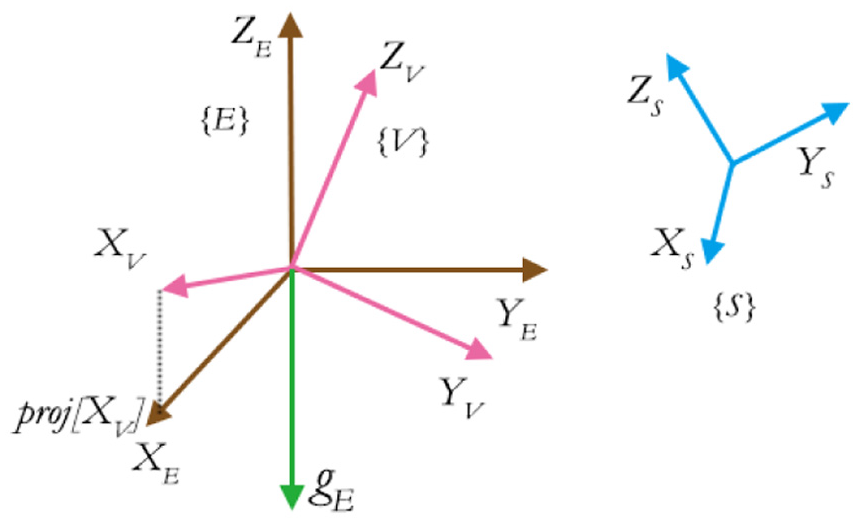
Gravity field and vision field.
The purpose of the orientation fusion is to estimate optimal quaternion transformation
The essential mathematical expression of one iteration at time t is shown as follows. Note that the orientation estimation from last iteration
Orientation derivative estimated by gyroscope
The three-axis gyroscope measures the angular velocity (rate) in rads about the three axes of
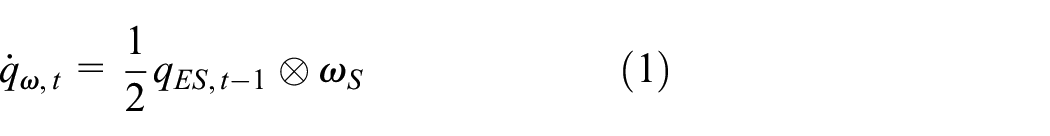
where ⊗ denotes a quaternion product. Note that all the quaternions in this article follow
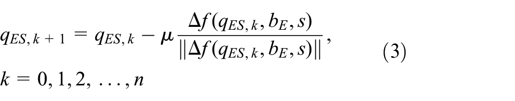
Orientation optimisation from homogeneous field
In order to obtain the optimal orientation estimation

where
where

Gravity field objective error function
Gravity field objective error function represents the error between gravity vector in principle and the sensed gravity acceleration vector, expressed in

where

Therefore, its Jacobian matrix is

Vision field objective error function
Vision field objective error function represents the difference between the vision field vector

where


where

where

Fusion of three sensors
As stated in the gradient descent algorithm,
21
given that the convergence rate of the estimated orientation is equal or greater than the angular rate of the physical orientation, only one iteration is required to be computed per sample time,

where
Moreover,

where

where

Gyroscope bias online estimation
Given the fact that the gyroscope bias drifts with temperature and motion, in practice, any high-accuracy fusion algorithm must be able to estimate the varying gyroscope bias online. Kalman-based methods generally cope with this by introducing the bias variables into the state vector. However, a much more computationally efficient estimation method is used by DC component of the angular error feedback, similar with Madgwick. 22
The normalised direction of the error in the rate of change of orientation,

The gyroscope bias,


where
Here, the weighting factor,

where
Position fusion process
This position fusion algorithm assumes that the orientation of the sensors is known and only estimates the translational state of the system. Being able to avoid estimating the orientation not only reduces the length of the state vector significantly but also keeps the system model almost linear. It takes three inputs: (1) the orientation estimation
Coordinate frame management process
Dynamic acceleration in earth frame
Different from the orientation fusion process, in the position fusion process, we consider that the accelerometer not only measures the gravity but also measures the pure dynamic acceleration caused by the movement of the body frame. And since the orientation estimation

recalling the normalised accelerometer measurement
Unscaled vision position in earth frame
The unscaled position estimation from mSLAM algorithm

Therefore, the resulting measurements in
Linear Kalman filter
The conventional KF framework consists of a prediction step, which performs the state vector time update in constant time interval; and a measurement update step, which performs the correction of the state vector based on the new sensor measurement. Here, in order to encounter the asynchronous measurements from both accelerometer and mSLAM algorithm, two different measurement update models are constructed and will be executed depending on which sensor measurement is available.
State representation and prediction model
The state of the KF is represented as a state vector

where position estimation
The state vector is updated once every time interval, following the rule defined by the prediction model, which defines the physics of the inertial system. It is summarised as


The linear acceleration


where
Following Welch and Bishop, 23 the discrete KF time update includes two steps:
1. State vector propagation to predict the state vector in next time step

where A is the state transition matrix, which is the Jacobian matrix of partial derivatives of the prediction model with respect to x.
2. State covariance matrix

where W is the Jacobian matrix of partial derivatives of the prediction model with respect to the noise vector, P is the state covariance matrix and
Measurement model
The measurement model is derived in the form of

where

where
When the accelerometer measurement

where
When the unscaled position measurement

And the vision measurement noise covariance
Following Welch and Bishop, 23 the measurement update steps are summarised as follows:
Compute Kalman gain

State vector update

State covariance update

Measurement update process handles different sampling rate between mSLAM and IMU estimation, by only updating state with the corresponding measurement, which becomes available. Thus, by assuming that the orientation fusion reaches steady state, the state vector x can be effectively estimated over time.
Implementation
This section describes the details on the algorithm implementation on an embedded platform. FreeIMU v0.4.3 (http://www.varesano.net/projects/hardware/FreeIMU) hardware was used as the IMU, which includes an MPU6050 gyroscope–accelerometer combo chip, an HMC5883 magnetometer and MS5611 high-resolution pressure sensor. However, only the MPU6050 was used in the algorithm. We performed orientation estimation in Teensy 3.1 (https://www.pjrc.com/teensy), which features an ARM Cortex-M4 processor with 96 MHz clock cycle. Besides, the real-time video frame was captured by an onboard uEye global shutter monocular camera in maximum 80 frames/s. Then, both the video frame and the orientation estimation are processed by the semi-direct monocular visual odometry (SVO) mSLAM framework with the extended Kalman filter (EKF) position fusion algorithm operating in parallel on Odroid-U3 (http://www.hardkernel.com/) single board-embedded Linux computer, which features an 1.7 GHz Quad-Core processor with 2 GB RAM. The communication between software packages is realised by Robot Operating System (ROS) (http://www.ros.org).
The entire system was installed on a quadrotor platform, 24 as shown in Figure 4. The autopilot board including the FreeIMU, Teensy processor, servo controller and XBee radio is shown in Figure 4(a). Since the components are overlaid to minimise the size, Figure 5 shows the top and bottom layers of the disassembled autopilot board, indicating the position of the FreeIMU and Teensy processor. The uEye camera and Odroid-U3 computer is installed underneath the quadrotor as shown in Figure 4(b).
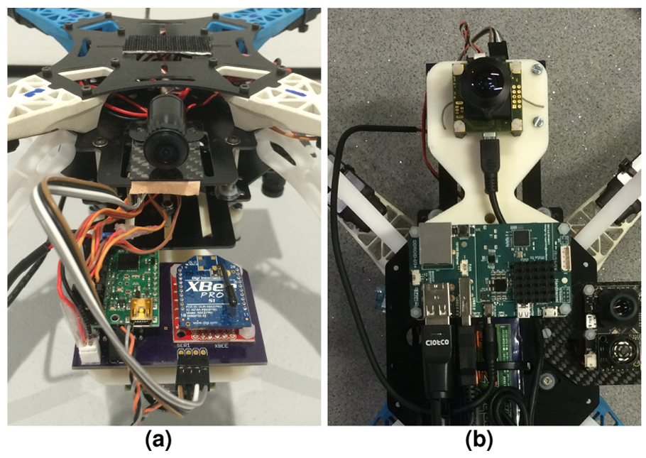
Hardware set-up: (a) freeIMU sensor and Teensy 3.1 processor and (b) uEye camera and Odroid-U3 computer.

FreeIMU and Teensy open up view.
The Teensy processor is capable of executing the orientation fusion alongside with autopilot control algorithm at 300 Hz while communicating with Odroid-U3 computer with ROS protocol, including publishing orientation estimation and acceleration measurement at 100 Hz and subscribing the pose estimation from SVO mSLAM framework in Odroid-U3. Moreover, in the Odroid-U3 computer, the SVO mSLAM is executed at 40 FPS with the KF position fusion algorithm running at 100 Hz in parallel.
We measured the simultaneous localisation and mapping (SLAM) processing delay and set the message buffer manually without hard synchronisation. The parameters set-up for both orientation and KF position fusion algorithm is summarised in Table 1.
Parameter set up.

Test results
Two test trials were performed to shown the effectiveness of the algorithm.
The first trial focuses on evaluating the scale factor
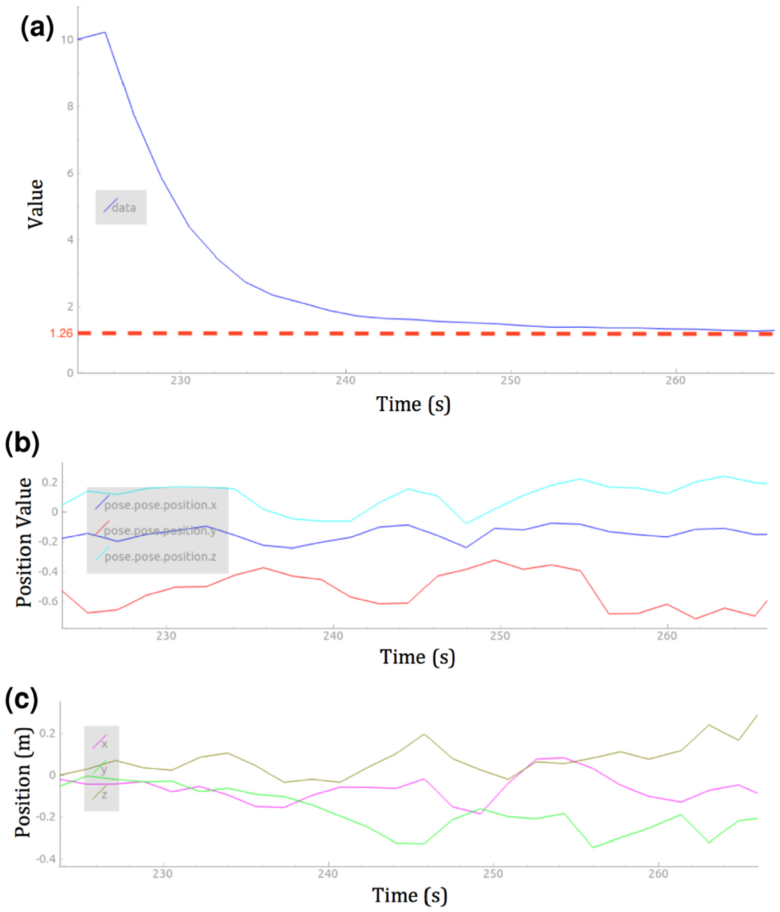
KF position fusion result: (a) scale factor λ, (b) the unscaled position measurement from SVO SLAM and (c) the scaled position measurement from KF position estimator.
The second trial evaluates the position and yaw angle estimation performance by comparing the estimation against the ground truth. The 6-DOF ground truth was provided by VICON (https://www.vicon.com) motion capturing system. Again, the movement was generated by handheld motion in about

Scale factor estimation.

Position estimation ground truth comparison.

Yaw angle estimation ground truth comparison.
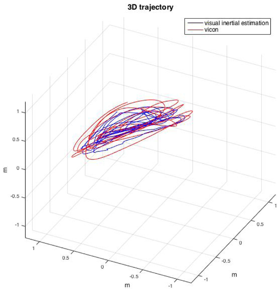
Three-dimensional trajectory illustration against ground truth comparison.
Conclusion and future work
This article has shown the design and implementation work of a sensor fusion framework, which is capable of performing the 6-DOF sensor state estimation, by the fusion of a three-axis gyroscope, a three-axis accelerometer and an mSLAM algorithm.
Two test trials were carried out to show the effectiveness of the system. The first trial shows that scale factor of the mSLAM can be sufficiently estimated from an arbitrary value, thus the position output is scaled accordingly. Whereas in the second trial, the comparison against ground truth shows that the 3D position can be effectively estimated, and the drift-free yaw rotation can be estimated accurately without magnetometer.
The future work includes estimation of error comparison and computational performance evaluation by benchmarking with other existing fusion algorithms.
Footnotes
Academic Editor: Teen-Hang Meen
Declaration of conflicting interests
The author(s) declared no potential conflicts of interest with respect to the research, authorship, and/or publication of this article.
Funding
The author(s) received no financial support for the research, authorship, and/or publication of this article.