
Abstract
The polishing process is the final step in the manufacturing workflow for many parts and tools. While previous tasks have evolved technically, the finishing of freeform surfaces is still effected mostly by hand. Many parts are rejected because no control of the process is possible. The main problems are geometrical shape deviations and no repeatability of the process. A new methodology has been developed for the passes of the abrasive on the polished part.
This research focusses on the feasibility of robotic polishing and the development of a new evolution model pertaining to the surface roughness for an abrasive tool mounted on a spherical robot. The polishing principle is mechanic and based on dry friction. The tool is multilayered with a compressive foamed core. The combination of rotational and translational movement requires the creation of a model that can predict the footprint on the polished surface. The mathematical model developed for the evolution model permits for making a prediction of the final surface quality in the function of the programmed polishing parameters. Furthermore, the model described allows for setting up polishing parameters in order to reach a desired final roughness with less than 15% deviation. Repeatability is assured and polishing time is reduced down to 1/5 of manually effected procedures.
Introduction
Generally, most finishing processes are primarily handmade according to operator experience. The lack of control in processing conditions is a consequence of manual operation. For this reason, it is not possible to ensure the reliability of the results in final products. Technological improvement of the finishing process is therefore needed. The process should focus on the automation of polishing processes of free form surfaces to ensure that they match all other manufacturing processes.
The polishing process is the final step in the value chain of part manufacturing. The lack of control in this process implies the more frequent rejection of parts than in other processes. As a result, not only the polishing task, but also all of the preceding processes have to be repeated.
Preston began research on the polishing process in 1890 and established the theoretical bases for determining the parameters that influence the amount of material removed. Previous studies for automating during the polishing process have been derived from his research.
Some research has been conducted in order to improve several fields related to finishing and polishing. Narayanasamy et al. [1] and Li et al. [2] analysed the defects appearing on parts during grinding and polishing processes and classified them. Sachtleber et al. [3] and Xhang et al. [4] studied the physical phenomena involved in some of defects such as colour changes and hardening.
Regarding methodology, some modifications based on the Preston Equation have been studied by Maury et al. [5], Hon-Yuen and Haobo [6] created some mathematical models for predicting material removal behaviour.
Several investigations have focused on automation with industrial robots in order to analyse the influence of robotic paths on results, e.g., Marquez et al. [7]. In this context, industrial trials were conducted for specific industrial sectors such as the tooling industry, e.g., Pessoles et al. [8] and Tsai et al [9].
Automated polishing is a necessity for several industry sectors and as a result, more research is being conducted for diverse applications such as complex ceramics, e.g., Klocke et al. [10] and for the wood furniture industry, e.g., Nagata et al. [11].
Many investigations on polishing were conducted for Pad and Slurry technologies, allowing for the fast evolution of this process. Nevertheless, this technique is not useful for free form surfaces, which are the focus for the research presented in this paper.
Computer controlled polishing has been extensively developed over the past several decades and commercially available processes and machines for such processes exist on the market.
QED's magneto-rheological finishing (MRF) commercializes different systems. The biggest of these is a multi-axis CNC machine equipped with a MFR tool. This tool entails a stable and continuous flow of MFR fluid where abrasive particles migrate to the polishing target surface under precise compression and shearing conditions [12–14]. Parts from 100 to 2.000 mm can be polished, depending on the selected machine. Magneto-rheological fluids have been studied in-depth [15,16] and their application in optics have been successfully developed [17].
Zeeko's intelligent robotic polishing (IRP) commercializes different systems. The biggest of these is a 7-axis CNC machine equipped with a device that polishes parts from small to large sizes with an abrasive suspended in a fluid. Previous research supports these systems with applications featuring large optic components [18–24].
OptiPro's ultraform finishing (UEF) commercializes different systems. The biggest of these is a bridge 5-axis CNC machine equipped with an abrasive belt made of polyurethane or specifically formulated materials [25–27].
The current research focusses on polishing with robots instead of CNC machines. The development and use of industrial robots is increasing within the industry, because they these machines have large pose freedom, as a minimum of 6DoF is involved. For using robots as final execution systems for polishing, two possibilities exist: (1) part to tool systems – when a robot holds the part and moves it against an abrasive belt; (2) tool to part system - where the part is fixed and the tool is assembled on a robot TCP.
The first system is useful for small light parts and is used within industry to polish small metal parts; however, it cannot manage high weight or large sized parts.
The objective of this research is to develop a methodology for optimizing final quality finishing parameters, using a robot in a tool to part system to enable the finishing operations on large metal components. The first approach to a solution is assuring quality requirements and eliminating rejected parts, as repeatability and dimensional geometry requirements are important.
The research presented in this article focusses to the prediction of the roughness evolution for a different polishing machine and a methodology for reducing time and fit quality requirements with its use. There are substantial differences between this research and existing commercial systems. An abrasive tool has been assembled ant the end of the robot to polish the parts. This tool is an abrasive that combines a rotational and translational movement to obtain a quality polished surface [28,29]. The article focuses on presenting an evolved model for surface roughness, which is necessary to understand and correct the defects derived from the mechanical features of the tool and its kinematics. The tool controls contact pressure with an intermediate layer of compressive urethane foam. The uniformity of the contact pressure allows for polishing flat or large curvature surfaces. The tool is assembled at the end of a spherical robot in order to precisely control the normal position and contact to the working surface.
This research investigates a different way of polishing small, medium and large size parts. The use of a robot instead of a multi-axis CNC machine allows for a more flexible manufacturing process. The use of a dry friction abrasive with control only of position is a non-expensive solution that can be widely distributed if accuracy and repeatability is ensured. This article shows that the above is possible under the proposed methodology. Future research is developed under the 7 Framework Program and the EU Project “Megarob” (Factories of the Future call) for the development of a flexible and automated platform for accurate manufacturing operations. These robots, tools and methodology will be implemented as one of the different manufacturing operations of the project. This will be possible only by considering the results shown in this article.
Further research and application of results shown in this article will lead to a new intelligent system in the future for finishing parts and tools with grinding and polishing technologies. It will incorporate the special development of artificial vision to obtain an automated system for reducing scrap and failed parts. This system will improve the environmental impact of traditional industrial processes, where actual non-controlled manual systems implies a significant amount of energy and raw material consumption to repossess the large number of faulty parts that are generated.
This new process will be applicable to different industrial sectors in the metalworking industry and specifically in aeronautical and automotive sectors, due to the improvement of the automation of manufacturing tasks that are currently used in these industries. In our case, this new tool based in the field of robotics will be useful for both metal and composite parts.
As a direct consequence, competitiveness between companies using the new system will increase, due to the integration of new industrial developments that will reinforce modernization, automation and optimization in the finishing process applied to parts and tools.
Materials and Methods
Materials and installation
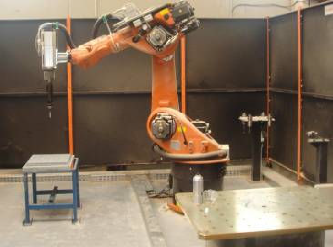
The polishing cell is based on an industrial robot, the Kuka KRC60HA (Fig.l). A robot controller is connected to an external PC on which CAM software is running. In this case, CAM software is used to create offline programming of the robot's trajectories, movements and poses in order to move the tool to polish the part. In a previous step, the part was designed in 3D CAD software. Then, robot trajectories were at the first instance generated with a standard CAM system for CNC machines. PowerMill (Delcam) software was used. One of the main advantages of using a robot is the flexibility of the use of 6D0F kinematics. CAM trajectories were established to maintain the polishing tool normal to the surface of the part in each point of the trajectory. Once the G-code had been obtained, it was translated into KRC2 language using intermediary software (Q-Design), where singularities were checked and some restrictions were included in order to better control the inverse kinematics solution of the robot controller. Once the simulation was deemed satisfactory, the file obtained was directly executed in the polishing robotic cell. The program contains the 6D0F coordinates (position and orientation) of the tool flange. Position accuracy is not the primary parameter, as the configuration of the polishing tool can absorb little positioning errors in terms of maintaining the polishing force. Previous research applied a rigid tool to perform polishing tasks on free form surfaces. The surfaces in these cases had regular geometries such as cylinders or spheres and required that the finishing tool geometry fit the exact shape of the part that was processed [10]. When some attempts of freeform complex geometries are effected, a force control system is used [7]. The intention is to control the force that the tool applies to the part during the finishing task. This system concept is considered valid for flat or planar surfaces; however, feasibility problems appear if convex or concave surfaces are involved. The system intends to apply a constant force to the tool and some over-polishing appears in convex areas, while a lack of polish appears in concave areas.
Finishing robotic cell and grinding and polishing tool
To avoid this problem, this research proposes a tool configuration [28,29], designed in such a way that it will maintain a constant pressure in all the points of the tool that are in contact with the work piece. To achieve this, a multilayer tool 50mm in diameter was designed, using an intermediate urethane foam layer that acts as a dumper that smooth the pressure variations. The thickness of the foamed core was 5mm and the pressure distribution was near constant for compression from 10% to 50%, so that large curvature radius surfaces could be uniformly polished.
The technological parameters and the kinematical parameters of the spherical robot used for polishing near flat surfaces were connected not only through the machining routes or through the developed program codes, but also through other robot parameters that would affect polishing quality.
Tool orientation. The tool orientation in the programmed points of the path was assured; however, there was still the possibility for programming the orientation of the robot flange while travelling from one point to the next. In the developed methodology, the orientation change is interpolated and modified in a constant manner while the robot travels, so that it is smooth and progressive. The use of this method is derived from that the CAM system and is programmed with a geometrical accuracy base. This means that for flat surfaces, the number of points generated is small and it increases in free form ones, such as curvature decreases.
Roughness evolution curve for ideal abrasive
Tool linear speed. It is essential that this be maintained as constant as possible, as it is one of the parameters that define the roughness of the final part. It is feasible to do this on flat or freeform surfaces. Some problems may occur in very small curvatures, where orientation of the tool needs to change very fast and robot motors could be overridden. However, these types of surfaces are not the focus of this research, because there are some limits to the tool due to its geometry and there are some curvature thresholds that cannot be exceeded. The size of the tool and the foamed layer compression limits determine the polishing force and define the minimum surface curvature that can be polished using this tool.
Rotational speed of the tool. This is generated by a 7.5 Kw. electric motor, which is commanded via a frequency inverter and a Profibus directly from the robot controller.
Due to the nature of the polishing process, surface states are obtained as a sequence of material removing operations derived from the use of a roughness evolution model.
This multistep system is translated via the use of a grain abrasive sequence, which starts on a rough abrasive (large grain size) and moves up to a soft abrasive (small grain size).
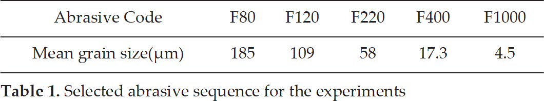
The abrasive sequence used for this experimental work is shown in Table 1, where the relation between abrasive code and mean grain size are detailed according to FEPA Standards 42–1:2006 [30] and ISO 8486 standard [31]. Mean grain size has a tolerance of up to +/− 20%.
Selected abrasive sequence for the experiments
Selected abrasive sequence for the experiments
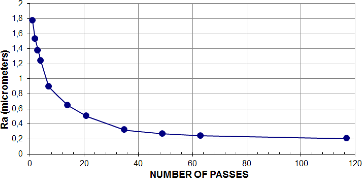
It is necessary to determine the evolution curve for each abrasive, [7, 32]. To analyse the evolution curve, a series of trials were performed for each abrasive. This evolution curve for a particular abrasive shows an exponential shape, decreasing as passes are executed (Fig. 2). All abrasives presented a similar shape that can be mathematically expressed as [7]:
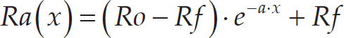
Where
Ra(x): Roughness in pass number “x”,
Ro: Initial roughness,
R f . Minimum reachable roughness,
a: Exponential coefficient
An Aluminium 5083 probe 200×100mm (Fig 3a) was used and the tool made passes on it. Figure 3b shows different abrasive tools and the resultant polished surface. The polishing tasks were completed using the following parameters:
Tool rotational speed: 6000 rpm
Tool translational speed: 12000mm/min
Tool-part interference: 2mm (equal to 40% porous layer thickness of the tool)
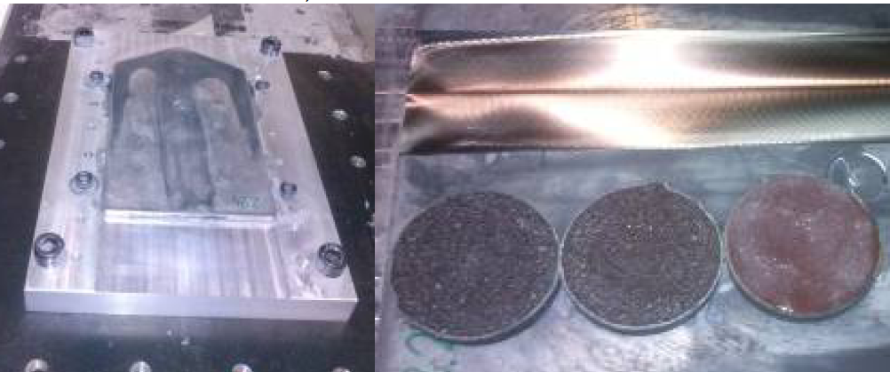
a) Original probe; b) polished probe and tools used
Individual passes of the tool were made and after each pass, roughness values were measured. For each individual abrasive, a sequence of more than 60 passes was conducted. Figure 4 show that all abrasives followed the exponential law in their respective sequences. The observed behaviour was that roughness starts at a Ro value, generally inherited from a previous manufacturing process or from a previous polishing step. Ra decreases and the tendency in this instance is stability in an Rf value, which can be understood as the minimum reachable roughness. Rf is the asymptotic extrapolation of the measured roughness tendency after more than 60 passes of the tool over the polishing surface. Measurements tended toward this Rf value, but will not be reached.
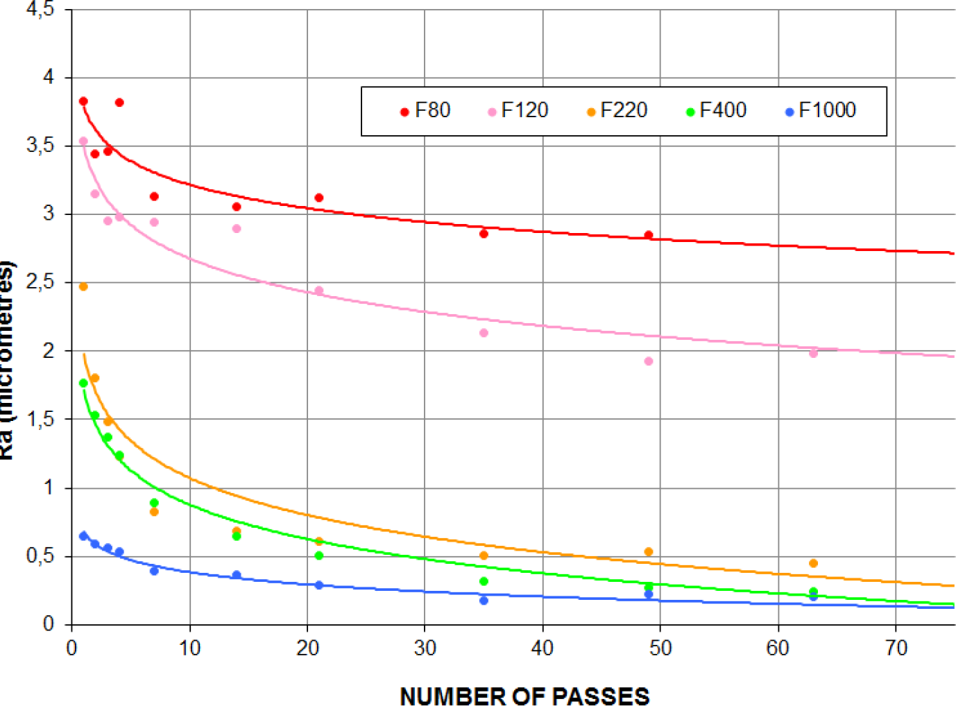
Roughness evolution curves for tested abrasives (F80, F120, F220, F400, F1000)
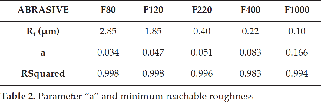
With the data obtained from the trials performed, a mathematical fit with a theoretical mathematical expression was created for each abrasive in order to determinate the minimum roughness reachable (Rf), as well as the coefficient of the exponential expression (a). Table 2 shows the results of the mathematical fit. Table 3 shows the part and abrasive surfaces after all passes have been completed.
Parameter “a” and minimum reachable roughness
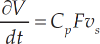
The mathematical model in 2.2 is dependent on the number of passes of each abrasive. According to Preston's Taw [5], the material volumetric removal rate is defined by the following equation:
×10 Image details of resulting surfaces and ×10 image details of the abrasive after the polishing process

Preston's law analyses the material volumetric removal rate and establishes dependence with the material (Cp), with the polishing force (F) and the speed (vs). These parameters directly affect the surface roughness.
In this research, Cp is considered constant, as it depends on the material used and it is not affected by polishing process parameters. In addition, F will be constant, as the tool geometry is fixed and contact pressure between tool and part is considered constant, due to the tool's design (2.1). Furthermore, speed (vs) varies in each point of the tool (Fig. 5).
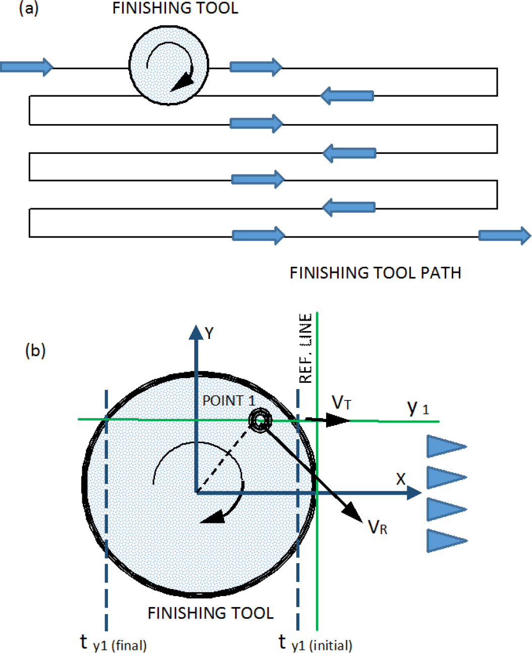
(a) Finishing tool path; (b) translational and rotational speed scheme
A mathematical model based on the Preston Equation was built. In order to define the punctual speed of the different points of the abrasive when finishing, the following model was made, because as Klocke et al. [10] noted, the maximum material removal is not found in the outer diameter of the tool. It is necessary to develop the influence function for the automated grinding and polishing process. The influence function defined in this paper will be used to evaluate the incidence of tool speed on the polished surface and its influence on material removal. The incidence factor attempts to predict relative removal depths.
Speed is controlled by two components; (1) the rotation of the tool (VR); (2) translation of the tool along the finishing path (VT). These components can be described as x-y coordinates referring to the main directions of the process.


After defining the module of the speed vector in each point of the tool, it is necessary to integrate the module in order to know how the work piece will be affected. The amount of material removed in one ref-line will be modelled. Ref-line is one cross cut section perpendicular to the tool's translational movement; y1 represents one line parallel to the central line of the tool path translation direction, y1 mm from the centre. In this case, different particles of the tool polish this line from initial time ty1(initial) to final time ty1(final). The initial and final time values that represent the limits for the integral are obtained as a solution of the circle equation that defines the tool geometry, as well as a line equation corresponding to the y1 line.

where R herr , is the abrasive tool radius.
Once defined, this part of the mathematical model can integrate the speed for each point of the ref-line and the result will be a value called incidence.

Incidence depends on rpm, tool diameter and tool feed rate. These parameters take part in the polishing process. Incidence represents how much time and in which conditions a point in the work piece surface is polished.
Figure 6 shows incidence factor values for a 30mm diameter tool, with 6000 rpm rotational speed and 12000mm/min translational speed, which were the parameters used for the trials in this paper. The shape of the incidence curve is identical to the curve described previously for surface roughness [15], demonstrating that incidence is a suitable factor for predicting the effect of polishing tasks on the work piece surface.

Incidence factor graphical representation

Incidence factor dependence on tool rotational speed and feed rate
This model was introduced in a mathematical simulator that graphically represents these values in terms of the function of the tool's rotational speed (rpm) and feed rate (mm/min) (Fig. 7).
Once incidence factor is analysed, we can establish a relationship between the number of passes of the polishing tool and the incidence factor. For a 30mm diameter tool, the dependence of surface roughness on the number of passes was modelled for each of the abrasives analysed in the research. The following expression was created to determine the number of passes required for achieving the desired final roughness.

Where:
Raf xx is the roughness programmed for F xx abrasive to be achieved
Ro xx is the initial roughness of the surface to be polished
Rf xx is the minimum reachable roughness for F xx abrasive
If is the incidence factor
n xx is the resultant number of passes with F xx abrasive to achieve Raf xx
As a conclusion of previously noted points, it is stated that a polishing methodology is a technological sequence of polishing phases for progressively reducing the roughness of the work piece surface.
Once an abrasives sequence has been chosen, the need arises for defining how many passes have to be executed for each one. Task overlaps and excessive working time must be avoided.
The sequence in this paper begins with a large grain size abrasive and finishes with the smallest one. One essential point of the research is the optimization of this sequence. As stated in previous research [20], in manual polishing operations, the finishing time for polishing parts represents 17%–29% of total parts production. In order to improve competitiveness within the industry, it is necessary to improve these figures in order to reduce the time to market, thereby increasing industrial profits. Automated polishing, as proposed in this paper, will in this context be a significant advancement; however, it has to be supported by parameter optimization.
For the above, it is necessary to establish the time for reaching abrasive change in the polishing sequence, to minimize the number of passes and optimize polishing time. In order to minimize the time that each abrasive is used, it is necessary to set the criteria that will be used as a threshold.
Exponential curve implies that roughness will gradually be reduced; however minimum reachable roughness (Rf) will never be achieved. The threshold criteria shows that abrasive change will be reached when roughness is 10% more than the minimum reachable roughness (1.1*Rf). Rf is the expected minimum roughness reachable with the “xx” tool and “xx” is the reference of the medium grain size of the abrasive at the end of using the multilayer tool.

Polishing roughness evolution curve for i/=0.852
Furthermore, another effect was detected when a new abrasive was used, referred to as Rnxx. Rnxx is the roughness measured on a probe's surface when a new abrasive is used for the first time. It can be said Rnxx is the roughness after passing the “xx” tool for first time. Trials conducted during this research revealed Rnxx values as shown in Table 4.
Roughness for a new, non-used abrasive (Rnxx)

The abrasive switch will be effected when the current roughness reaches the Rnxx value of the next abrasive or 1.1*Rfxx value of the actual abrasive. Using this criteria, Figure 8 shows the sequence of abrasives optimized for if= 0.852. The blue horizontal lines correspond to switches where roughness reaches the first Rn value of the next abrasive. The purple lines are thresholds where roughness reaches 1.1*Rf first.
In order to make a validation of the developed mathematical models for predicting the roughness values in the function of the programmed parameters for the polishing process, several tests were conducted. A 30mm diameter tool with a thickness interference of 2mm was used, similar to those used for the probes.
Test 1: One line polishing lengthwise in one trial part
Polishing process conditions:
Tool rotation speed: 6000rpm
Feed rate: 12000 mm/min
If 0.852
Initial mean roughness Ra=0.55μm
With information of initial roughness for the part, the mathematical model predicted that the optimum polishing process that needed to be performed was 20 passes with an F400 abrasive and 18 passes with an F1000 abrasive in order to reach a final roughness Ra=0.11 μm. Figure 9 shows the details of the obtained results.

a) Polished part; b) surface detail (x10)
Table 5 shows data of the estimated roughness using the prospective model and the actual average roughness obtained for each polishing step.
Model programmed roughness and results obtained

Polishing process conditions:
Tool rotation speed: 6000rpm
Feed rate: 6000 mm/min
If: 1.643
Initial mean roughness: Ra=0.68 μm
With the information regarding the initial roughness of the part, the mathematical model predicted the optimum polishing process to be performed as 13 passes with a F400 abrasive and 10 passes with a F1000 abrasive, in order to reach a final roughness Ra=0.11 μm. Figure 10 shows the details of the obtained results.

a) Polished part; b) surface detail (x10)
Table 6 shows data pertaining to the roughness estimated using the model and the actual average roughness obtained for each polishing step.
Model programmed roughness and the results obtained

In this instance, a full part was polished. Path lines [6] were programmed in a CAM system, following on one another in an overlapping manner. Distance between the lines in the trajectory was programmed to ensure that each point of the work piece was polished with the number of passes programmed into the mathematical model for each abrasive.
Polishing process conditions:
Tool rotation speed: 6000rpm
Feed rate: 12000 mm/min
If: 0.852
Initial mean roughness: Ra=0.68 μm
To validate the repeatability of the model, two identical sample parts were developed and processed using the same conditions. Figure 11 shows the details of the obtained results.
Table 7 presents data of the roughness estimated using the proposed model and the actual average roughness obtained for each polishing step in each polished part.
Model programmed roughness and the results obtained
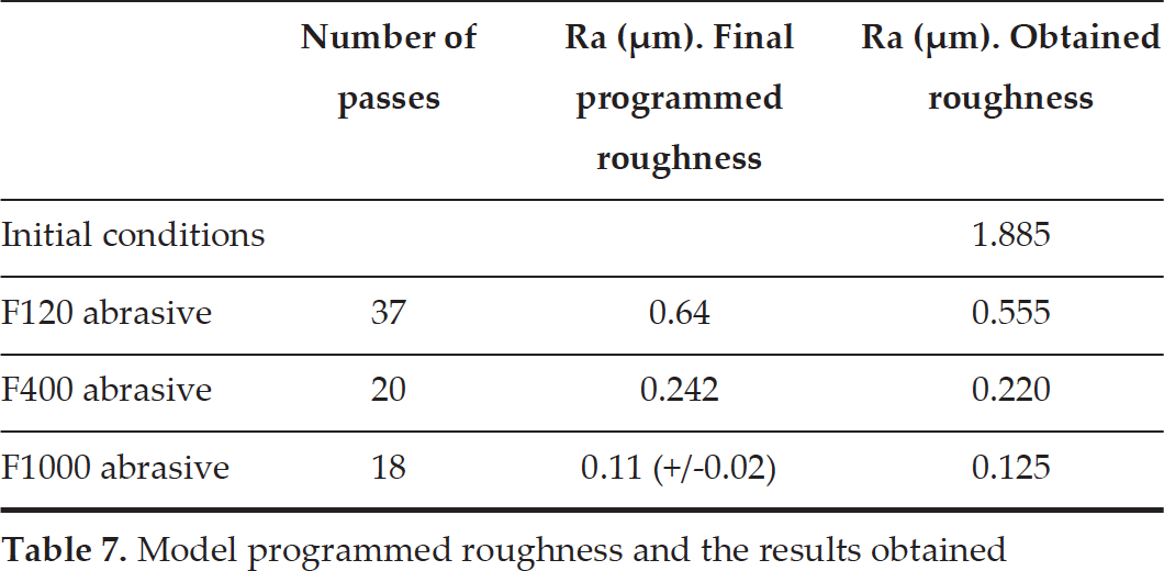
Model programmed roughness and the results obtained
The full process time consumption measured for the test including three parts was 256 seconds for a surface of 160cm2 (for each part). By extrapolating the results, it was found that the newly developed automated polishing methodology permits for polishing aim2 aluminium part in less than five hours, reducing roughness from 2 μm to 0.1 μm; that is, five times faster than manual polishing.
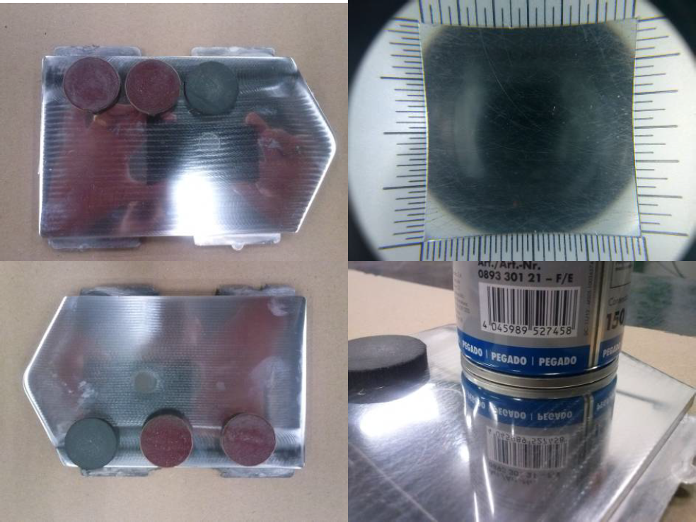
a) Polished part; b) surface detail (x10); c) polished parts; d) detail of the reflection
Current polishing processes are affected manually in most industrial sectors, especially for high benefit parts. This manual manufacturing has revealed a lack of control that reduces repeatability, geometrical accuracy and surface quality parameters.
The current research represents a step forward in polishing process automation, as several milestones have been achieved:
Exponential curve validation for polishing tools. The curve of the roughness evolution acquired with the applied number of tool passes has been proven exponential and parameters have been described and characterized for several abrasive grain size tools.
Exponential coefficient and minimum reachable roughness have been analysed for different grain size abrasives.
The mathematical model has been developed to relate number of passes to surface roughness achieved.
A mathematical relationship has been found to exist between polishing technological parameters such as rotational and translational tool speed and the number of tool passes effected to achieve the required surface roughness. This relationship was introduced as the “incidence factor”.
A polishing methodology has been developed; a switch and threshold was stated to establish the number of passes for each abrasive in the described sequential polishing methodology.
All the developments have been included in a mathematical model that has been validated, allowing for predicting the final surface roughness in relation to the parameters set for the process. Moreover, the model allows for knowing the parameters required for reaching a desired roughness.
A mathematical model was designed in order to minimize process time consumption, reduce the minimum the number of passes of the abrasives and for setting abrasives changes at the optimum moment.
The methodology and polishing model was validated through several test parts and obtained deviations less than 15% between the model and the current actual polishing process. New research and development is required to apply the methodology to new materials and abrasives.
Future development of the proposed polishing system will reduce by 5 polishing time consumption respect current process. Manual process is still mainly used in flat or large curvature surfaces contained in medium and large size parts. The proposed polishing method has the limitation that the final reachable roughness is influenced by the use of dry friction sandpapers. Tower tolerances will require the application of other types of tools that are magneto-rheological, abrasive fluids and others.
The uncertainty of quality inherent in medium grain size tools suggests that it is necessary to refine the criteria for tool changes. For fine grain size abrasives, it has been observed that the Rf value is lower than expected; thus, 1.1*Rf should be increased. For coarse grain size tools, the roughness values reached were mostly below 1.l*Rf. Under these conditions, a particular coefficient should be included to slightly increase the value of 1.1*Rf in order to ensure the quality of the polished surface more accurately in the case of fine abrasives.
The methodology described was CAM based and is therefore applicable for small production lots, or even customized parts.
The roughness values obtained during the research were good enough for most industrial sectors; however & is needed in order to achieve the requirements for optic applications.
& is also needed for the future application of robots where the polishing of large parts is concerned.
Additionally, new efforts must be made in selected areas to reduce processing reduction where polishing is concerned. In this context, & must focus on the automated identification of initial roughness parameters in order to efficiently select the abrasive and to minimize the number of tool passes. In this way, abrasives can be applied in each zone depending on the initial distribution of part quality. Results based on human inspection have recently been published by Dieste et al. [33],
Footnotes
Acknowledgements
This research was partially funded by the Spanish Ministry for Economy and Competitiveness under the INNPACTO funding program, reference IPT-020000-2010-034.