
Abstract
Polishing process is one of the most critical manufacturing processes during a metal part production because it determines the final quality of the product. Free-form surface polishing is a handmade process with lots of rejected parts, scrap generation and time and energy consumption. Two different research lines are being developed: prediction models of the final surface quality parameters and an analysis of the amount of material removed depending on the polishing parameters to predict the tool footprint during the polishing task. This research lays the foundations for a future automatic conformal polishing system. It is based on rotational and translational tool with dry abrasive in the front mounted at the end of a robot. A tool to part concept is used, useful for large or heavy workpieces. Results are applied on different curved parts typically used in tooling industry, aeronautics or automotive. A mathematical model has been developed to predict the amount of material removed in function of polishing parameters. Model has been fitted for different abrasives and raw materials. Results have shown deviations under 20% that implies a reliable and controllable process. Smaller amount of material can be removed in controlled areas of a three-dimensional workpiece.
Introduction
Finishing processes as polishing are present in most of the manufacturing workflows for industrial parts. Polishing is still a handmade process that requires research and development to increase the quality and reliability, reduce the parts rejection or time–cost and reach the challenges described in the strategic research agendas of the factories of the future. Researchers have been sensible during the last years to this problem trying to solve it through different research strategies.
The chemical mechanical polishing (CMP) was developed during the last 20 years and has rapidly grown as a core technology in the manufacturing of semiconductor devices due to its excellent flattening capacity.1–4 The CMP is based on a rotating table, a polishing head and a suspension pad, where the surface of the wafer moves across the pad, under pressure, in the presence of slurry abrasive. The mechanical movement and the downward force are applied to the wafer by the machine. The surface of the pad provides the rough spots, or asperities, which contact the wafer. The liquid suspension provides the abrasive particles and the right chemistry for the CMP performing.
The use for semiconductor industry makes CMP broadly develop during the last years. Combination of electrochemical finishing and burnishing has shown successful results on bore surfaces. 5 This polishing process is an example of how technology evolves to new industry requirements. CMP process is used to planar surfaces but is not applicable to three-dimensional (3D) free-form shapes. Then a different process has to be used.
Automation of general polishing process is required to be used in different industrial sectors, such as aeronautics, automotive and tooling industry. Common characteristics to these industrial parts are that the main shapes are 3D free form. To finish these surfaces, CMP is not valid and the complexity of the geometrical surfaces leads finishing to be done manually.
This research is focused on a future automated method to polish metallic parts based on robotics. Industrial robot is a very flexible machine that allows a large possible poses range. This enables to process surfaces in a large workspace. Control systems permit to process them with the correct tool angle position. Advantages of a 6-degree of freedom (DOF) robot, compared with other machines used for polishing process, are mainly related to the low investment that robot purchase supposes in comparison with milling machines, 6 turning machines or special machines. 7
Recently, some intends to develop an automated polishing system based on robotics. There are two main concepts that can be used. The most extended is a part to tool philosophy that consists in one robot that handles the part and makes it go against an abrasive belt.8,9 This is used in general industry to finish lightweight metallic parts, but it is not useful for heavy weight parts, that are the main objective of this research. Ultraform finishing (UFF) is a set of different-sized five-axis CNC machines equipped with an abrasive belt. They are commercialised by Optipro.10–12 Then for heavy parts, as aeronautic aluminium parts, aluminium and magnesium automotive parts, or moulds and tools for industry, a tool to part concept is going to be used. In this case, robot handles a rotational tool and describes polishing trajectories over the workpiece that remains fixed in the cell.
Computer-controlled polishing systems have been commercialised recently. Magneto-rheological finishing (MRF) was developed since the end of the 1990s,13,14 and QED Technologies International, Inc offers different machines for optical applications with multi-axis CNC machine to polish parts up to 2.000-mm length. In the field of large optical parts, polishing Zeeko commercialises an intelligent robotic polishing (IRP) technology based on seven-axis CNC machine using abrasive suspended in a fluid.15,16
Researches to make this process automated should solve the problems that current manual polishing is carrying on, which are derived of the control lack in the process. Manual polishing requires of expert operators with a large experience but final quality part depends on their skills. The human intervention in polishing shows the absence of repeatability and involves a lot of part rejection. Lack of control in the process can be divided in two essential lines:
No control in the methodology that defines the final surface quality parameters as roughness and brightness. Although majority of the polishing operators have a lot of experience, tools, abrasives, movements and methodology differ in each case. This has an important influence in the final aspect of the part and the time consumption in the process. The operator itself fixes the quality threshold, so the final quality of the part does not depend on objective criteria.
No control in the amount of removed material. Manual polishing consists in a fuzzy sequence of movements of the abrasive on the workpiece. The only intention is to remove the previous marks, so there is no control on the material that is removed in each area. It derives in a lack of geometrical control of the shape of the polished part. Over polishing derives in rejected parts due to the final shape does not fit the geometrical requirements that should be achieved. In the rest of the cases, warpage or deformations in the surfaces are generated during the manual polishing.
Previous research has been done in order to improve the state of the art in several fields related to finishing and polishing. Narayanasamy et al. 17 and Li et al. 18 analysed defects appearing on parts during grinding and polishing process and classified them. Sachtleber et al. 19 and Xhang et al. 20 studied the physic phenomena that involved some of the defects as colour changes and hardening.
Several investigations focused on automation with industrial robots to analyse the influence of robotic paths on the results.21–25 In this line, Huissonn et al., 26 Pessoles and Tournier, 27 Feng et al. 28 and Tsai et al.29,30 have shown that industrial trials were made for specific industrial sectors such as tooling industry.
This research has been performed in order to control the roughness of the part during automated polishing processes that is one of the goals to be achieved.
In this research, material removed by the tool has been analysed for a tool to part robotic polishing process.
Regarding material removal, some modifications based on Preston equation has been studied, Maury et al., 31 for CMP.32–36 Even some pure mechanical polishing processes have been modelled analysing contact stress 37 and influence of parameters on processing time. 38
In the case of pure mechanical polishing that is the focus of this article, some mathematical models were done by Tam and Cheng 39 to analyse the final surface aspect in function of the typology of the polishing paths used.
During this research, a new model has been developed to predict tool footprint for a rotational sandwich tool. In addition, it has been determined how technological polishing parameters affect the amount of material removed and the final geometrical shape of the part. This model has been developed for a wide range of abrasives and has been tested in several materials.
The large control on the prediction obtained permits to open new research lines to achieve a conformal polishing process.
Materials and methods
Materials and installation
This investigation is based on a robotic system. Several machines such as milling machines were compared to perform polishing task in industrial environment. Due to the movement flexibility, the small maintenance and relative low investment, an industrial-size conventional robot KUKA KRC60 HA (Figure 1) was adapted and installed to perform polishing task in an automated way.
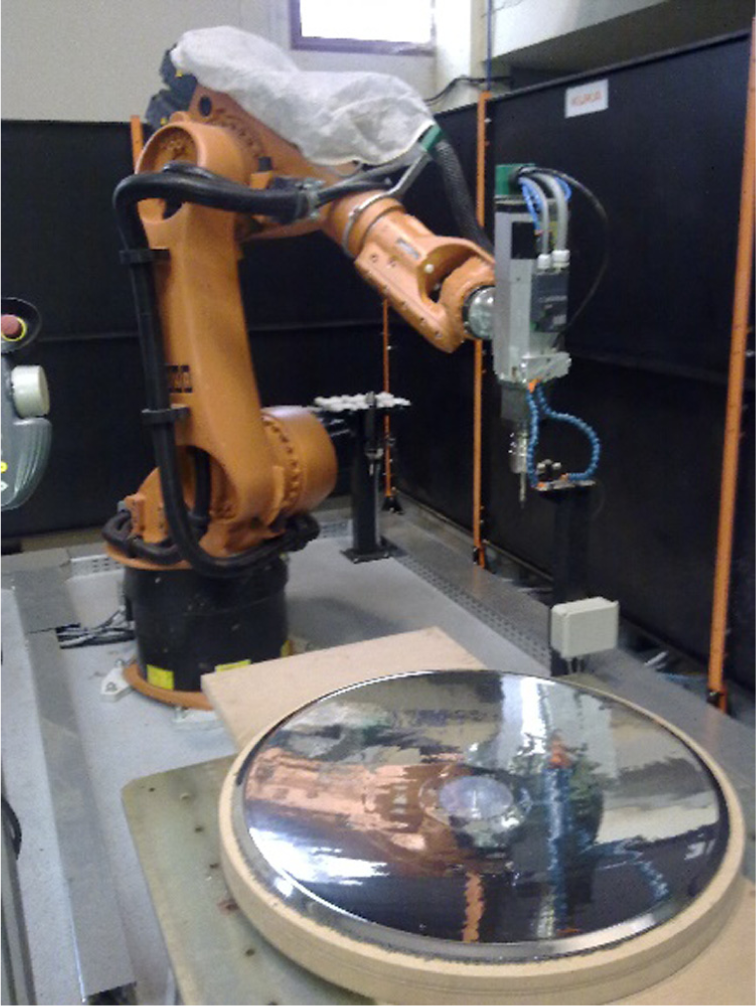
Finishing robotic cell and grinding and polishing tool.
Robot controller is connected with an external PC where computer-aided manufacturing (CAM) software is running. In this case, CAM software is used to make an off-line programming of the robot trajectories, movements and poses to move the tool to polish the part. Delcam’s PowerMill is the software used.
Some previous research uses rigid tool to perform polishing tasks on free-form surfaces. In these cases, surfaces of revolution such as cylinders or spheres are polished as it is required that finishing tool geometry fits exactly the shape of the part. 40 Free-form surfaces or complex geometries require the use of a force control system. 41 Research about process control, 42 force control43,44 and compensating error due to machine force 45 has been developed recently for aspheric surfaces. The intention is to control the force that the tool is applying to the part during the finishing task. This system concept is probed valid for flat or planar surfaces, but in the case of convex or concave surfaces, new problems appear. 46 When a constant force is applied to the tool over polishing appear in convex areas while a lack of polishing affect the concave ones, so that constant force control can be applied only if tool shape fits with workpiece surface. 47
To overcome the problem, a new tool is used46,48 in this research. This tool maintains the nearest constant pressure in the contact surface between the tool and the workpiece. The design consists in a multilayer system comprising an abrasive layer assembled on the top of a urethane closed pore foam layer, which is mounted over a rigid metallic support. In this research, a rotating 30-mm-diameter tool with a 5-mm-thickness urethane core is used. It generates uniform contact pressure for thickness compression in the range of 10%–50% of the core. Non-flat, large curvature radius surfaces were successfully polished.
Probes and test configuration
Investigation performed by Preston showed that the rate of material removed during polishing processes depends on the materials, the contact force and the relative velocity. As the objective of this research is to apply a constant pressure, the test trajectories are programmed to perform interference between abrasive and workpiece of 40% of the urethane foam layer thickness. Material for initial probes is aluminium 5083, and parameters obtained will be extrapolated and tested for magnesium and steel F114.
Because of the nature of polishing process, the surface states are obtained as a sequence of material removing operations. For this reason, the use of a roughness evolution model is needed.
Polishing is a multistep process that uses abrasive to remove material, this concept is translated in the use of a grain abrasive sequence, that is starting on a rough abrasive (large grain size) till a soft abrasive (small grain size).
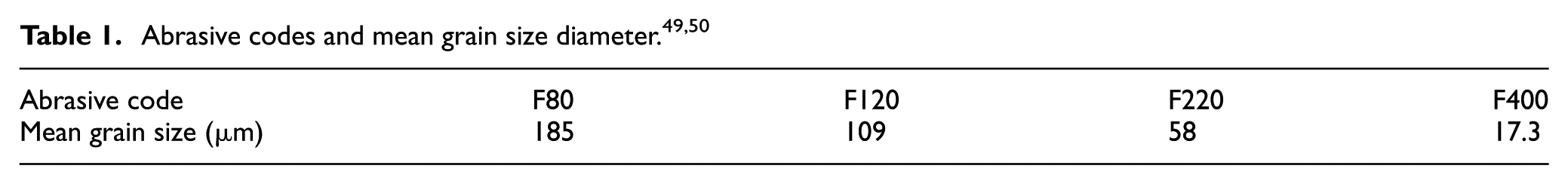
In this research, the abrasive sequence is not crucial, as tool footprint is going to be analysed for a single abrasive separately. Abrasives used are shown in Table 1. The values of mean grain sizes are extracted from FEPA-Standard 42-1:2006 49 and standard ISO 8486 50 and have a tolerance of ±20%.
For each abrasive, it is necessary to determine the evolution curve.21,51 To analyse the evolution curve, a series of trials have been performed for each abrasive. Once parameters related to pressure and material are fixed, the main parameters that will influence the material removal are those related to tool speed. In the case of a tool to part system, these are the rotational speed of the tool and the translational speed (feed rate) following the trajectory over the workpiece. The design of experiments for aluminium and magnesium is shown in Table 2.
List of test parameters.

Tool footprint measurement
Regarding the tool footprint prediction during finishing process, some previous researches were made in robotic-assisted polishing, also some researches focused on laser polishing, water jet finishing or belt-based grinding. Even material removal prediction is important in cases of stone finishing,52,53 that is one of the main application industries of finishing technologies, but the importance of this prediction is also shown in the interest of finishing commercial machines’ manufacturers, as the case of Zeeko, in order to support the finishing process and implement process control instruments in their finishing machines. In our case, the intention is to predict the tool footprint for a robotic-assisted mechanical finishing process. To reach this objective, once the probes are polished, the footprint of the tool is measured in a confocal displacement metre (CdM) machine. Polishing process removes a small amount of material so that several passes were made in the same line. The depth of the tool footprint is increased this way in order to make the footprint visible for the CdM machine. Tool footprint in length direction (direction of the robot trajectory) is constant so only the cross section must be analysed. Figure 2(a) shows dimensional measuring process and Figure 2(b) an example of measurement.

(a) Measuring process and (b) dimensional results of the tool footprint.
Each probe is measured in several cross sections. Data obtained from the collaborative decision-making (CDM) software have to be post-processed. Each footprint has to be extracted, its graph has to be centred and inclination and deformation of the top surface of the probe has to be compensated. Figure 3 shows the tool footprint representation for several polishing conditions. Tool footprint covers a 30-mm length in x direction, corresponding to the diameter of the tool.
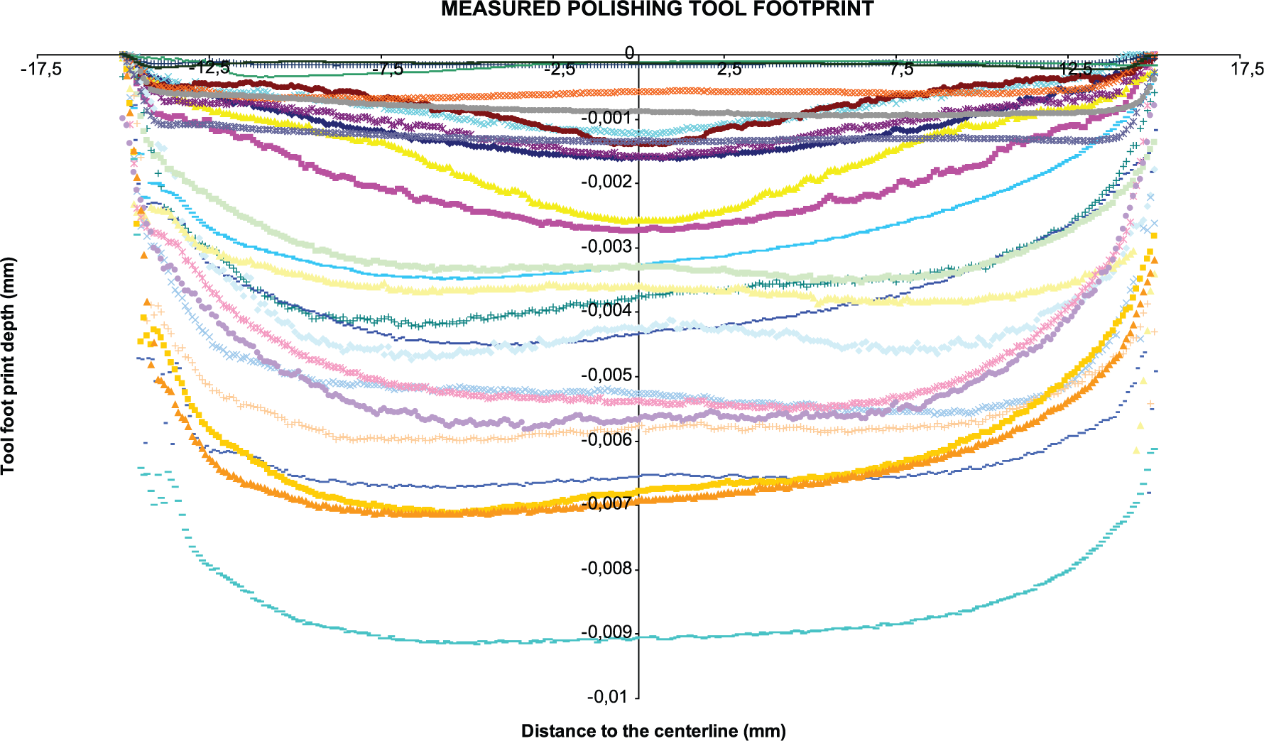
Tool footprint measurements.
Tool footprint depth model
The main objective of the research is to characterise the tool footprint that the abrasive tool produces on the workpiece surface. First step is the development of a model for the maximum depth. For this reason, the maximum depth value is related to the polishing parameters. The following methodology is the analysis of all the probes with F80 abrasive polishing aluminium 5083 material. Figure 4 shows the results for different translational and rotational speeds of the tool.
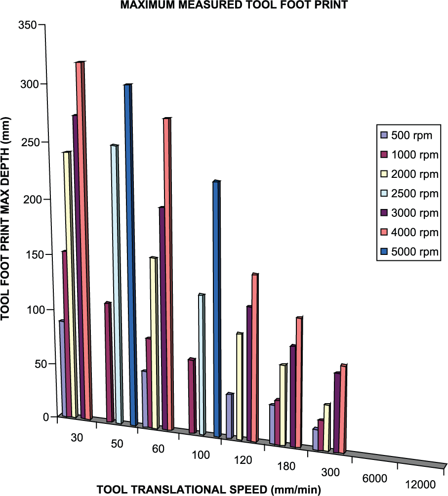
Maximum measured tool footprint values.
The analysis of the data obtained shows an exponential behaviour. The mathematical model that fits with the results then is an exponential curve that can be expressed as

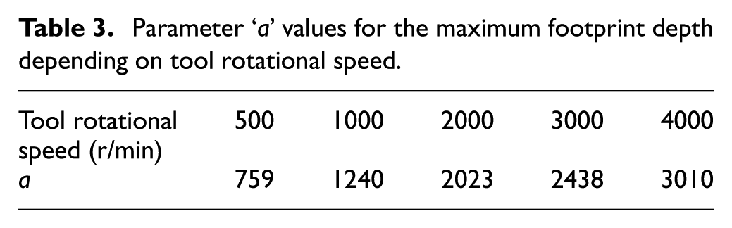
In the case studied for F80 abrasive and aluminium 5083, ‘b’ fitted value is constant and equal to 0.631. Table 3 shows ‘a’ values for different tool rotational speeds.
Parameter ‘a’ values for the maximum footprint depth depending on tool rotational speed.
Based on the model obtained, Figure 5 shows the actual values measured on the probes and the theoretical mathematical exponential curve that best fits them.

Modelled maximum tool footprint and measured values.
Figure 6 represents the evolution of parameter ‘a’ with tool rotational speed revealing a logarithmic behaviour tendency.
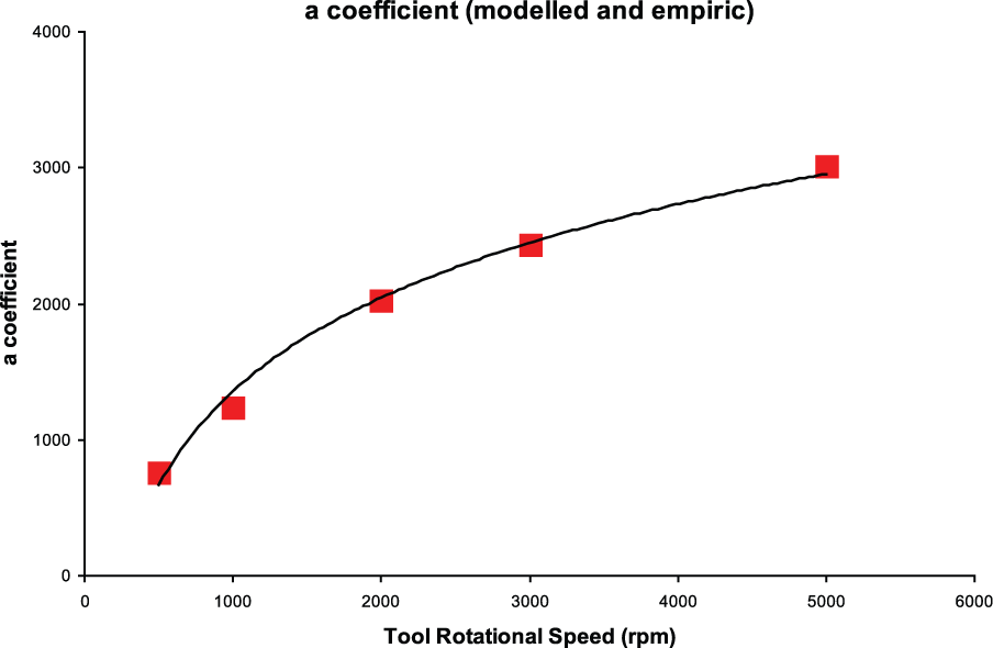
‘a’ coefficient values for the minimum value of the tool footprint.
The curve fit of the ‘a’ coefficient values obtained can be mathematically expressed as

where ‘rpm’ is the tool translational speed in r/min.
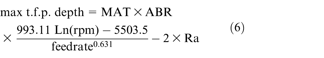
Then, the maximum tool footprint depth can be modelled in function of the polishing technological parameters

where rpm is the tool rotational speed (r/min), feed rate is the tool translational speed (mm/min) and average error of the maximum tool footprint depth mathematical model is under 5%.
In order to model the whole curve of the tool footprint, the same methodology is used for the mean value of the footprint depth. A constant value for ‘b’ parameter is obtained (b = 0.687). Table 4 shows the values for parameter ‘a’ and Figure 7 its graphical representation and logarithmic tendency.
Parameter ‘a’ values for the mean footprint depth depending on tool rotational speed.


‘a’ coefficient values for the mean minimum value of the tool footprint.
The mathematical expressions for ‘a’ and mean tool footprint depths are


Average error of the mean maximum tool footprint depth mathematical model is under 5%.
Tool footprint depth model generalisation for other abrasives and materials
The mathematical model developed permits to express maximum and mean tool depth values as functions of the parameters programmed as the input in the robotic polishing process. These parameters are related to tool speed and rotational and translational movements. This mathematical model is based on the data obtained for a specific material, Al5083, and a specific abrasive, F80.
In order to generalise and extrapolate results for other materials and abrasives, ‘material’ and ‘abrasive’ coefficients (‘MAT’ and ‘ABR’) are introduced to adapt the mathematical model. Table 5 shows the results obtained for several combinations of workpiece materials and abrasives for maximum and mean values of the tool footprint depth.
Maximum and mean tool footprint values for several materials and abrasives.

t.f.p.: total footprint.
Based on the results shown in Table 5 and additional results for Steel F114, the correction coefficients are calculated including material (‘MAT’), abrasive (‘ABR’) and roughness (‘Ra’) effects. During this research, 65% of the tests were made on AL5083 material. This amount of trials also increased by tests performed during previous phases,46,48 provides the authors a significant amount of results, so Al5083 is used as reference when defining the ‘MAT’ coefficient. Regarding ‘ABR’ coefficient, F80 has been broadly used in previous tests because tool footprint obtained is deeper and easier to be measured than in less rough abrasives. During this research in 70% of the tests, this abrasive was used, so it was set as reference abrasive when determining ‘ABR’ coefficient. Results are shown in Tables 6–8 for ‘MAT’, ‘ABR’ and ‘Ra’ coefficients, respectively.
‘MAT’ coefficient for several materials.

MAT: material.
‘ABR’ coefficient for several abrasives.

ABR: abrasive.
Ra coefficient for several abrasives.

Ra: roughness.
Finally, it is necessary to perform a little correction due to the fuzzy oscillations (Figure 8) of the footprint curve derived from the roughness of the surface.

Typical measured tool footprint.
Then taking into account abrasive and material conditions, tool footprint depth equations are as follows

Mathematical model obtained has been compared with the 64 tests performed, and average deviation is under 25%.
Tool footprint depth cross section model definition
Once determined the mathematical model that defines the maximum tool print depth for several materials and abrasives in function of the polishing conditions, a further step is to model the shape of the full cross section of the tool footprint. As it was stated in the previous sections, polishing pressure is not considered. This is one of the parameters that would affect the footprint, but the tool design keeps this value nearly constant if conditions of the robot trajectory allow the interference to remain within the range cited in Section ‘Materials and installation’.
The main parameters that will affect the shape of the curve are tool speed parameters and robot speed conditions, which in fact are the components of a combined movement (translational and rotational) as represented in Figure 9. Figure 9 shows both movements of the tool, rotational in Figure 9(a) and translational due to the robot movement in Figure 9(b). One point in the workpiece that is located at a distance y1 from the centre line of the robot toolpath shows an absolute speed with two components Vr and Vt. These can be translated to a Cartesian coordinate system

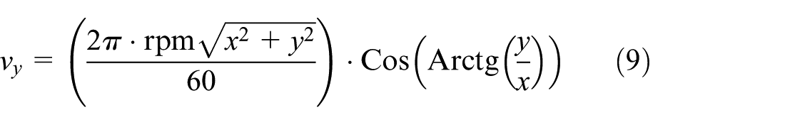

where feed rate is the translational speed (speed of the robot moving on the workpiece) (mm/min) and rpm is the tool rotational speed (r/min).

Speed schema of the contact between one point in the tool and one point in the workpiece: (a) tool kinematics and (b) finishing tool path.
Simplifying the expression

In order to analyse the amount of material removed, that is the focus of this point of the research, not only instant speeds are considered, it is necessary to define the amount of time that any particular point of the workpiece is suffering this speed. As consequence, an integration of the speed is made in function of the time. Next function incorporates the time as variable in the equation


The objective is to define the cross section of the footprint. Tool footprint cross section represents values for a yi point, when yi goes from ‘−Radius’ of the tool (−Rtool) to ‘+Radius’ of the tool (+Rtool).
For this point of the cross section, located at a distance yi from the centre line, integration has to be made from the time instant when tool starts to polish this point
To determine limit values for the integration, it is necessary to calculate

Once defined the limits of the integration, the model for the cross section of the tool footprint depth can be described as
From yi = −Rtool to

Figure 10 shows the curve obtained from the model developed.

Tool footprint cross section obtained from the model developed.
Tool footprint depth cross section model adjustment
Typical shape obtained from the model developed fits roughly with the actual shape obtained from the probe trials performed. The reason is that it is necessary to include a correction coefficient that balances the weight assigned to the translational and rotational speeds.
Hocheng et al. 54 analysed the non-uniformity in CMP finishing and concluded that it is majorly determined by the ratio between carrier speed and platen speed, which in the case of robotic mechanic tool to part finishing could be identified as rotational and translational speed of the tool. They described an index that described the kinematic effect in non-uniformity.
During this research, this coefficient is going to be called ‘speed factor’ and will modify the equation of the component of the speed in translational direction (direction of the robot movement) such a way vx equation will be as follows

‘Speed factor’ will magnify or dwarf the rotational versus translational influence. Figure 11 shows several simulations of the cross section tool footprint for different values of ‘speed factor’.

Tool footprint cross section for different ‘speed factor’ values.
Now it is possible to fit ‘speed factor’ depending on the polishing parameters (feed rate and tool rotation speed)

Tool footprint depth cross section model simulator
The finalisation of the model will integrate all the developments in previous sections:
Mathematical model for the minimum value of the tool footprint depth;
Mathematical model for the cross section of the tool footprint;
Corrections with ‘speed factor’.
This integration describes the complete mathematical model of the cross section of the tool footprint. To achieve this objective, all the models are included in new software. In the programme, first part is the parameter declaration, where user is required to define material, abrasive code, rotational tool speed, tool diameter and robot translational speed.
Moreover, in this section, coefficients such as ‘ABR’ and ‘MAT’ are defined in function of the user selection.
Then, ‘speed factor’, ‘maximum tool footprint depth’ and ‘mean tool footprint depth’ are calculated. Speed factor determines the shape of the graph, taking into account the non-uniformity of the section obtained derived from the rotational and translational speed of the tool.
After this point, the calculations based on the methodology developed in the research will run based on the mathematical model, and it will be scaled in function of the ‘max t.f.p. depth’, obtained from the algorithm execution. ‘Mean t.f.p. depth’ is used to check the scale obtained from the ‘max t.f.p. depth’ value calculated. The output from the software will be the tool footprint section graph predicted for the parameters and values of the specific finishing task.
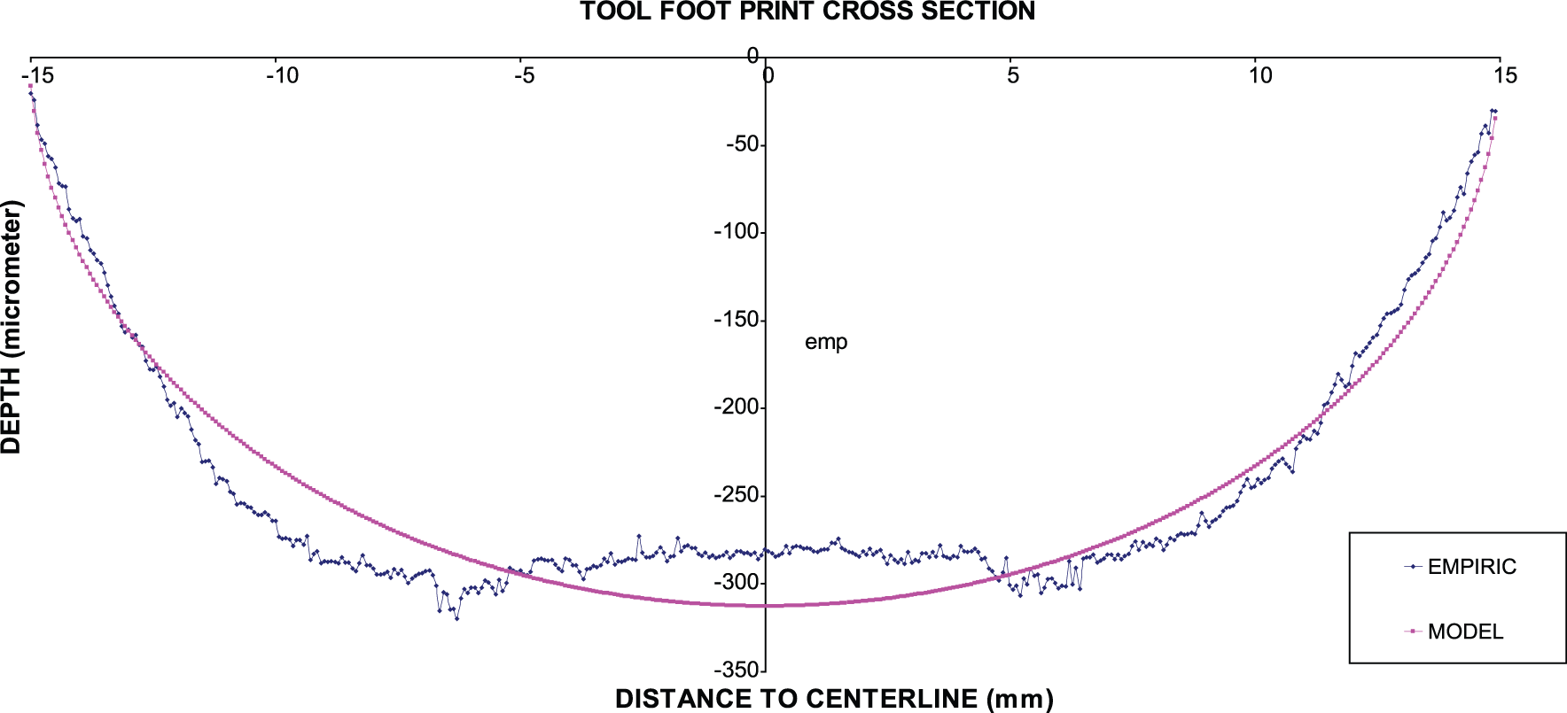
We can compare the results obtained from the software with the measured data obtained during the trials. Figures 12–15 compare the model with the actual empiric data for several input conditions.
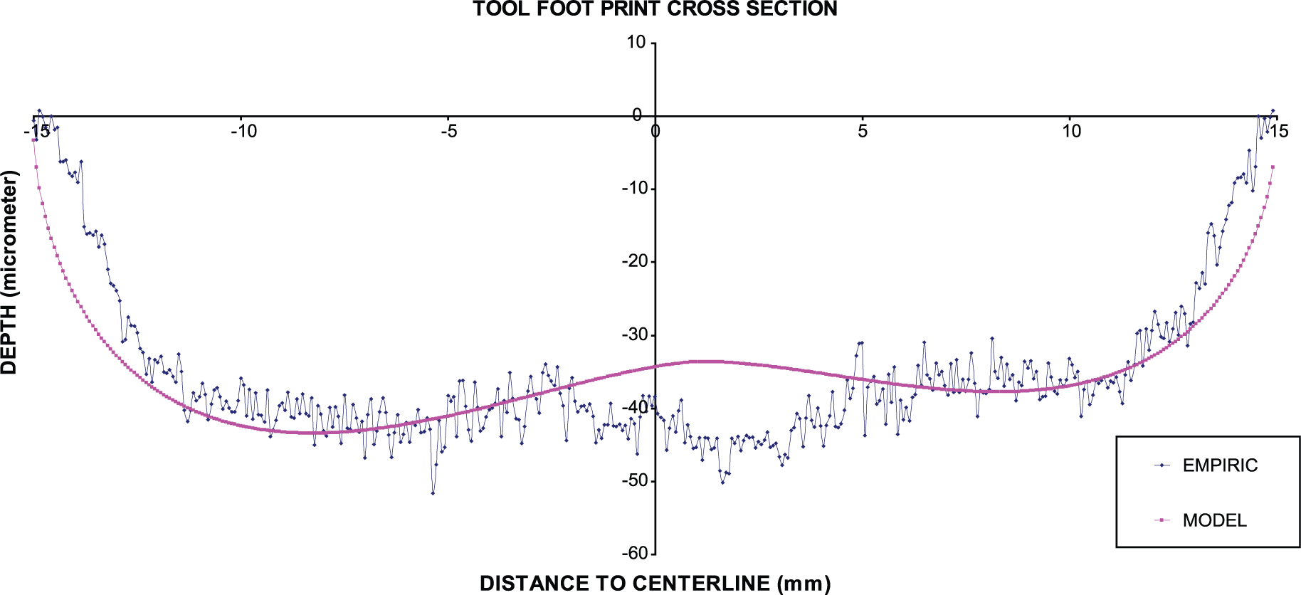
Polishing parameters modelled and measured tool footprint cross section.

Polishing parameters modelled and measured tool footprint cross section.
Polishing parameters modelled and measured tool footprint cross section.

Polishing parameters modelled and measured tool footprint cross section.
Conclusion
The aim of this research was to tackle the question of developing a technological base to improve the polishing process. It is a fact that cannot be ignored that as a consequence of traditional, manually made finishing process currently performed in the companies, a series of quality problems remain in the present days. These are derived from the lack of control process. Specifically, there is not control on the amount of material removed and the quality of the final surfaces. Even in current process, most of the quality thresholds depend on the subjective criteria of a skilled worker.
The issue under consideration can be summed up as the fact that during this investigation a ‘tool to part’, automated polishing process based on industrial robotic is demonstrated as a suitable manufacturing system to automate this finishing task.
A complex mathematical model has been developed that uses as input the technological polishing parameters such as tool rotational speed, robot translational speed and variables related to polished material and abrasive to be used. The model generates as output a prediction of the tool footprint cross section graph.
The model developed has been programmed in a software in order to automate the tool footprint prediction.
The results of the model have been compared with the experimental trials performed in different metallic alloys such as aluminium 5083, magnesium alloy and steel F114 (for several abrasive grain sizes (P80, P120, P220 and P400), with a rotational tool speed in the range of 500–8000 r/min with a 30- to 50-mm-diameter tool, and translational tool speed in the range of 30–12,000 mm/min). Maximum absolute deviations between the model and the empiric results remain under 25% in the worst cases and under 15% in most of them.
Model developed is a grant to implement robot ‘tool to part’ polishing in industrial environments and industrial applications.
Moreover, the accuracy in the prediction of the amount of material removed by the abrasive can set the base for a ‘conformal polishing’ concept. This means not to use polishing process exclusively as a surface finishing task, but also as a new predictable manufacturing process. It will allow removal of a very small amount of material through a controlled way. This concept could be applied in the near future to correct shape deviations in metallic parts or even to make a part fit a programmed shape.
Footnotes
Academic Editor: Yong Tao
Declaration of conflicting interests
The author(s) declared no potential conflicts of interest with respect to the research, authorship and/or publication of this article.
Funding
The author(s) received no financial support for the research, authorship and/or publication of this article.