
Abstract
Robotic surgery offers various advantages over conventional surgery that includes less bleeding, less trauma, and more precise tissue cutting. However, even surgeons who use the best commercially available surgical robotic systems complain about the absence of haptic feedback in such systems. In this paper, we present the findings of our project to overcome this shortcoming of surgical robotic systems, in which a haptic-enabled robotic system based on master and slave topology is designed and developed. To detect real-time intrusion at the slave end, haptic feedback is implemented along with a programmable system on chip, functioning as an embedded system for processing information. In order to obtain real-time haptic feedback, force and motion sensors are mounted on each joint of the master and slave units. At the master end, results are displayed through a graphical user interface, along with the physical feeling of intrusion at the slave part. Apart from the obvious applications of the current system in robotic surgery, it could also be used in designing more intuitive video games with further precise haptic feedback mechanisms. Moreover, the results presented in our work should pave the way for further scientific investigation, to provide even better haptic mechanisms.
Keywords
Introduction
Nowadays, robotic systems accompanied by haptic feedback mechanisms are receiving attention from many researchers. Haptic-enabled devices are being used in many real-world problems: for example, augmented reality, surgical robotics and intelligent manufacturing [1, 2]. Haptics promises a revolution in our interaction with the virtual world. It can be divided into four broad areas of research: haptics involving human interactions, machine haptics, haptics through multimedia, and haptics using computers. Computer haptics involves the creation and rendering of the touch of virtual objects under observation [1]. Surgical robotics systems allow a reduction of patient trauma, recovery time, energy consumption during the operation, overall cost, as well as a reduction of assignment completion by 30% and a reduction in error by 60% [3, 4, 5]. Robotic surgery without haptic feedback leads to ambiguities in surgical operations [6,7]. Minimally invasive robotic surgery has also gained attention as a result of the integration of haptics with surgical procedures [8]. Such procedures involve the training of surgeons using virtual simulators before performing actual surgical operation on patients. The gaming industry has recently improved a lot, with the inclusion of virtual reality and tactile perception. This has greatly enhanced the gaming experience as it existed a few years ago [9]. Game developers are focusing their attention on user interaction during game play, instead of enhancing visual graphics [6]. Actions during the game can be translated from inputs to an output, according to the capabilities of the hardware in use [4]. There are many haptic-enabled devices available in the market these days: for example, the da Vinci, the PHANTOM, the MiroSurge and the Novint Falcon. These systems are not yet ready to be commercialized and a lot of improvements are required by these various different devices [10,11,12,13].
A team of researchers from our university has developed a complete tele-surgical robotics system [14]. However, a haptic feedback mechanism is missing not only from this system, but also from the best commercially available robotic systems [15].
The programmable system on chip (PSoC) (Cypress Semiconductor Corp., USA) is a new technology being used these days to build embedded systems [16]. It has many advantages over FPGA and microcontroller technologies; for example, the fact that it contains both analogue and digital peripherals results in a compact system design, low cost, system-level configuration, and open-source libraries [17, 18]. It has dynamic reconfigurable abilities, meaning the ability to change design at software level [19]. FPGA and microcontrollers are lack analogue components. PSoC has system-level programming, which is less time-consuming and more user-friendly, when compared to the other available devices on the market. The design of the embedded system on the PSoC reduces the overall cost of the system by a great extent. PSoC can be updated remotely by its system manufacturer; for example, the user have an oscilloscope functions on PSoC, the manufacturer could update its system remotely, just like updating a software package nowadays. Systems composed of a master-slave topology are currently being used in many applications, e.g., surgical procedures and manufacturing industries [20].
The system's sampling frequency must be high enough to avoid lags in the feedback from slave to master and master to slave; a communication protocol is therefore established between the two sides of the system. Thus, its stability largely depends upon the communicational link between subsystems, i.e., the master and slave units [21].
A working prototype of a robotic manipulator equipped with a haptic feedback system was developed and analysed. The overall embedded system for communication and control was designed on a PSoC. The reliability of the proposed low-cost haptic feedback system can be seen from experimental results.
This paper consists of five sections. The theoretical background relating to all the subsystems used, as well as the already available systems on the market and the case setup, is explained in Section II. The system design is presented in Section III. Implementation using the PSoC is discussed in Section IV. The experiments and their analysis are outlined in Section V. Finally, Section VI presents a conclusion and proposes future work.
Theoretical Background
Haptics refers to our sense of touch, relating to surrounding objects and our environment. This sense can be experienced through human means as well as those of machines, and the environmental objects can be either real or virtual. Interaction can be made possible by the inclusion of visual and auditory sensors [1]. The major components and terms necessary to build a haptic system are explained below.
Master Slave Topology
A master-slave topology is used because the movement in the master is replicated for the slave, thus solving many of the problems encountered in conventional control methods through, for example, improvements in terms of ergonomics, the removal of hand trembling, and a reduced consumption of time.
The unilateral control system involves only visual feedback and there is no intrusion feedback from the slave end. It is an easy system to build and control [20,22]. In the bilateral master-slave topology, along with visual feedback, there is also intrusion or tactile feedback from the slave end, via different types of embedded sensors on the slave end. Later, this feedback is replicated at the master end, and appropriate hardware is used to produce the exact force or tactile feedback. This is more complicated than a unilateral control system [20].
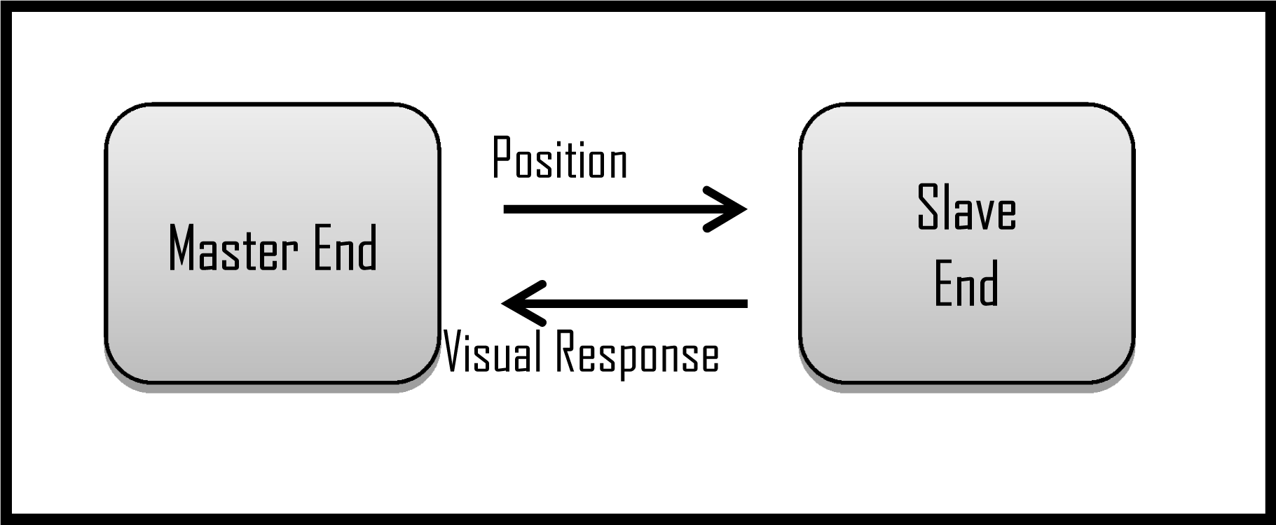
Unilateral control system
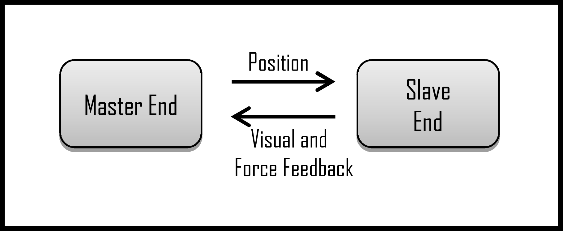
Bilateral control system
Many embedded development kits have been used to build control system for both haptic feedback systems and master-slave topologies. FPGA-based systems are mainly used to build embedded control systems, because of their rapid prototyping ability [18]. An STM32 development board, along with other peripherals, has been used to control a tele-operated robotic arm [23]. The programmable system on chip (PSoC) (Cypress Semiconductor Corp., USA) is a relatively new development board, which is increasingly being used to build embedded systems. This kit includes all the peripherals needed to build a control system for a haptic feedback system using a master-slave topology [24]. The inclusion of field-programmable analogue arrays (FPAAs) and digital blocks on the same chip leads to a compact and low-cost system design [25]. In order to perform two different functions, the same digital or analogue blocks can be selected in different time slots, due to the dynamic reconfiguration ability of PSoC [19].
Developers are able to choose from different versions of PSoC according to the system under development, as shown in Figure 3 [17]. The configurations of the different versions of PSoC are given in Table 1.

Block-wise view of PSoC (Cypress Semi. Corp., USA)
Along with the physical replication of intrusion from the slave end, there should also be visual feedback at the master end of the robotic system. Visual feedback can be displayed on a PC or any other appropriate device, according to the application. Visual feedback might be composed of a graphical view of force feedback and a video stream of the events occurring at the slave end. To allow users to interact with the visual feedback, a graphical user interface is required. There are many software programs available to perform this job: for example, Microsoft Visual Studio, Lab VIEW and MATLAB [26, 27, 28]. Microsoft Visual Studio is used to design the control and graphical user interfaces. It enables the easy development of a system and its testing on bases.
Features of PSoC families

Features of PSoC families
The overall system configuration is shown in Figure 4. The user has access to a PC and the hardware part of the master, which is connected to the slave end via a communication link managed by PSoC.

Overall System configuration
The master end is composed of pitch, yaw and gripper movements. A hardware mechanism is used to achieve these three motions, as shown in Figure 4. Current sensors are embedded, along with motor drivers, to measure the exact current drawn by the load during operation. When the user physically interacts with master-end hardware, the exact same motions are replicated at the master end via communication link. Digital encoders are used to determine the position of each joint. Along with the replication of motions, the user can also feel the force through the master hardware, as it is applied by intrusion at the slave end, i.e., the actuators at the master end oppose the user through an intrusion of the gripper, pitch and yaw movements. The exact amount of opposition is regulated by the amount of current drawn during operation, within each movement.
Kinematics and GUI
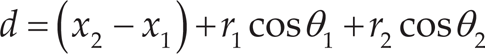
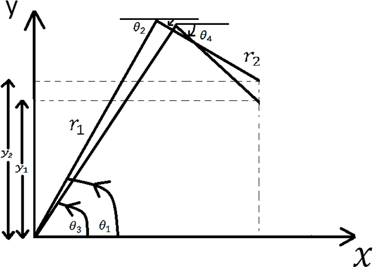
Kinematic equations are solved for the slave manipulator's joint movements other than yaw, pitch and gripper movements. The movements of these joints are controlled by the PC through GUI, while the yaw, pitch and gripper are controlled by the master hardware. As Figures 5, 6 and 7 demonstrate, in order to allow the slave unit to cover space, in terms of its polar coordinates system, θ1 and θ2 are the angles of Motor 2 and Motor 3 at the starting point, while θ3 and θ4 are the angles of Motor 2 and Motor 3 at the required new position of the robotic arm manipulator. The goal is to find the corresponding θ3 and θ4 values for the motors in the new position. The end results, after resolving the corresponding components in a radial direction, are as follows:


where


Similarly, for vertical or z-axis movement in the polar coordinates system, the corresponding components have also been resolved. The final results for required new position are shown as follows:


where


Movement along radius
Movement along z-axis
The motions produced by motors 1–3 are controlled by the PC using a GUI interface. Motor 1 is used to cover the circular motion of the slave end around its axis, as shown in Figure 7. Microsoft Visual C# was used to build the GUI for observing and controlling visual events at the slave end. This is a programming platform used to create PC applications for the Microsoft Windows operating systems. It combines the C# language and .NET framework for development purposes. C# is a smart object-oriented language that allows developers to build a variety of applications with flexibility, which run on the .NET framework. Visual C# has an advance code editor, a user-friendly interface, an integrated debugger, and many other tools used for development.

Computer-aided design of slave end
PSoC (CY8CKIT-001) is used for communication and control purposes between the two ends. CY8CKIT-001 represents the device number of a generic PSoC kit used for prototyping an embedded control system for the robotic manipulator. Control signals from both master hardware and GUI are received and translated into corresponding PWM signals. PWM signals are then transferred onwards to the motor drives of the slave system. These signals are generated by the PI control system implemented on PSoC. Other than driving all the joints of the slave, PSoC also receives and transmits the analogue data from the sensors (i.e., the force and current sensors).
The Slave End
The slave end is used for the manipulation of the object under observation. In order to interact with the object, it performs pitch, yaw and gripper movements controlled by the master hardware, while the rest of the joints are controlled through GUI, using a PC. The gripper has force-sensitive resistors, as shown in Figure 8. These sensors are embedded inside the jaw, in order to detect the exact force that it exerts upon the object under observation.

Force sensor embedded inside the gripper's jaws
A force vs. resistance curve is presented in Figure 9 for reference purposes [29]. To check the maximum endurance of the sensor against applied force, a silicon rubber with a spherical shape and a 4mm radius is used. The sharp decrease in the curve around 100kΩ is due to the actuation force necessary to bring the sensor into the range of measurable resistance. This turn-on force depends upon the shape of the object and the thickness of the spacer between object and sensor. Under intermediate forces, resistance follows an inverse power law, and this trend slows down because of the saturation achieved by the response curve under higher forces. In order to process the information obtained from the force sensor, it is necessary to convert the resistance value into voltage using a voltage-divider circuit, as shown in Figure 10 [29]. For further computational tasks, the acquired voltage is converted into digital form through the built-in ADC in PSoC.
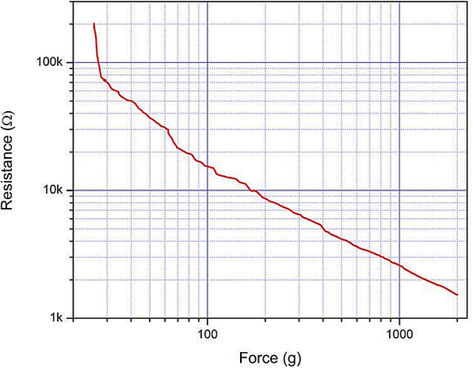
Maximum and minimum ranges of resistance, with respect to force applied
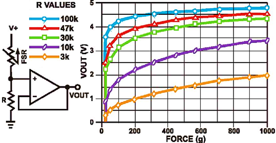
Obtaining a suitable voltage curve using a voltage divider for force sensor
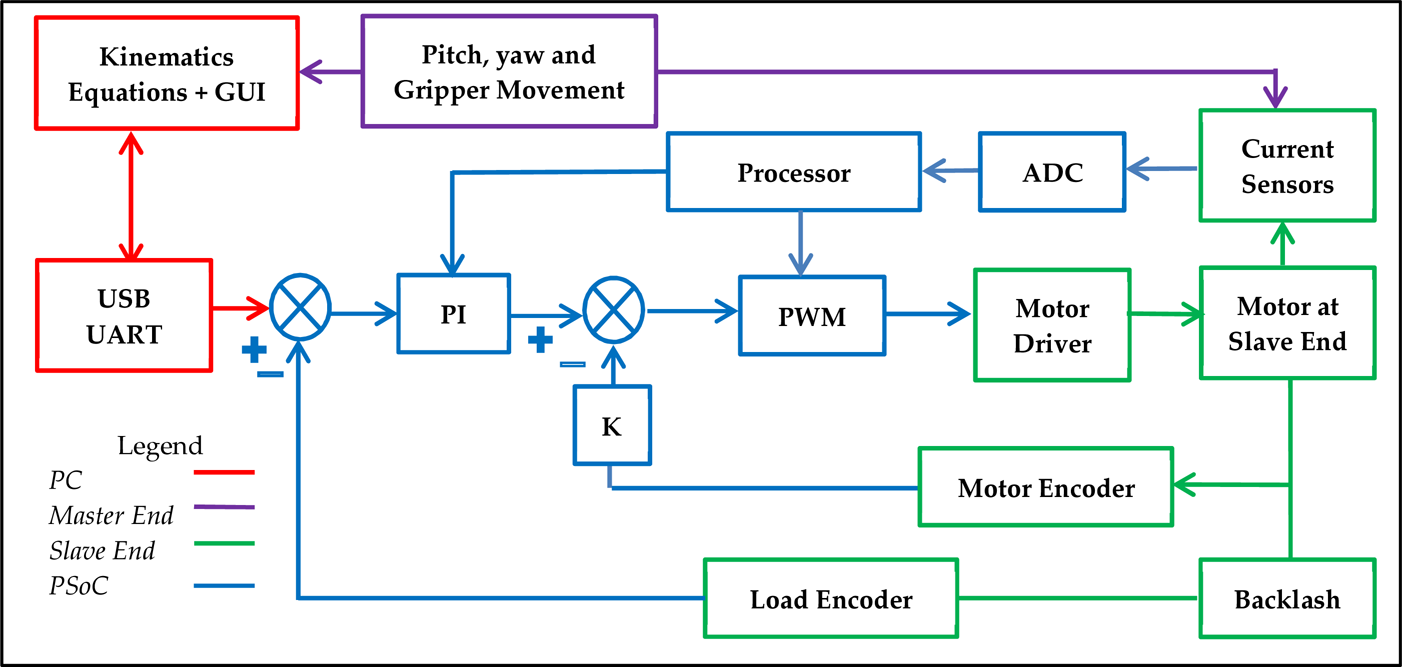
The implementation of the overall control system is shown in Figure 13. As discussed previously, the master hardware unit is responsible for the yaw, pitch and gripper at the slave end, and the rest of the motions are controlled via a PC along with GUI. The master hardware delivers positional commands to the PC, which processes these along with the rest of the motions using kinematics equations. Communication between the PC and PSoC is achieved via USB to avoid any delays during real-time operations. The PI controller for each joint is implemented on PSoC to avoid any mechanical gear backlash. PWM signals are generated by PSoC to drive motors at each joint. The percentage of PWM is determined by the PI controller, the values from the positional encoder, and the results of the kinematics equations.
Motion Controller
PI controller is used to prevent backlash due to gears of motors. Two encoders are used to develop a dual loop control system. Backlash is the movement of the motor's rotor, without moving any load. Backlash causes nonlinearity in systems and leads to poor accuracy and precision. The linear encoder is attached to the motor's rotor shaft and is used to tune the PI controller, in order to avoid positional errors. The inner loop is embedded with the compensation K and depends on the velocity of the motor. The second encoder is attached to the load, to compensate for backlash error before bringing the PI controller into action. Hence backlash-free movement is possible with the dual loop. The main purpose of using a dual-loop controller is to fix positional errors, along with backlash avoidance, which can't be achieved with a single-loop controller.
Current Sensors
The current sensors are embedded on each joint and are made by using low-value resistors attached serially to the wire of the motor, which draws current as shown in Figure 11. The voltage around 0.5Ω is fed to the analogue-to-digital converter embedded inside the PSoC kit. The digitally converted value of the voltage drop is processed accordingly to determine the intrusion at each joint of the slave end. More force applied by an object under manipulation would lead to a greater voltage drop across the resistor.

Current sensors implementation
As Figure 12 shows, a 16-bit delta-sigma ADC is used to convert analogue inputs into numerical values of voltage drop, where FSR_1, FSR_2, AMux and eco represent the force sensor resistors, analogue multiplexer and digital output, respectively. In order to feel a physical force feedback, pitch, yaw and gripper movements are replicated at the master end, by driving the motors in an opposite direction to the slave end. The torque generated in the opposite direction at the master end depends upon the digital values of the current sensors. The values of the current sensors on both ends are compared, for exact force replication. The change in PWM at the master hardware, with respect to intrusion at the slave end, is shown in Figure 14.
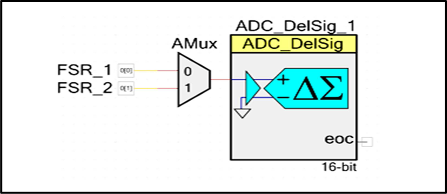
bit delta sigma ADC implementation
Overall system implementation
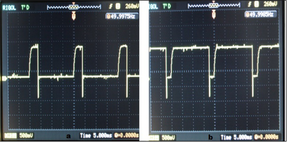
Change in PWM at master end
As previously discussed, system-level programming is performed on PSoC, in order to build an overall embedded system for the robotic manipulator.
The top-level module for implementation is shown in Figure 15. Each joint has a dedicated PMW module to drive it. A USB module is used to establish a linkage between the two ends to avoid communication lag, and an LCD module is used for debugging purposes during the design of the overall system.

PSoC modules used to design the embedded system
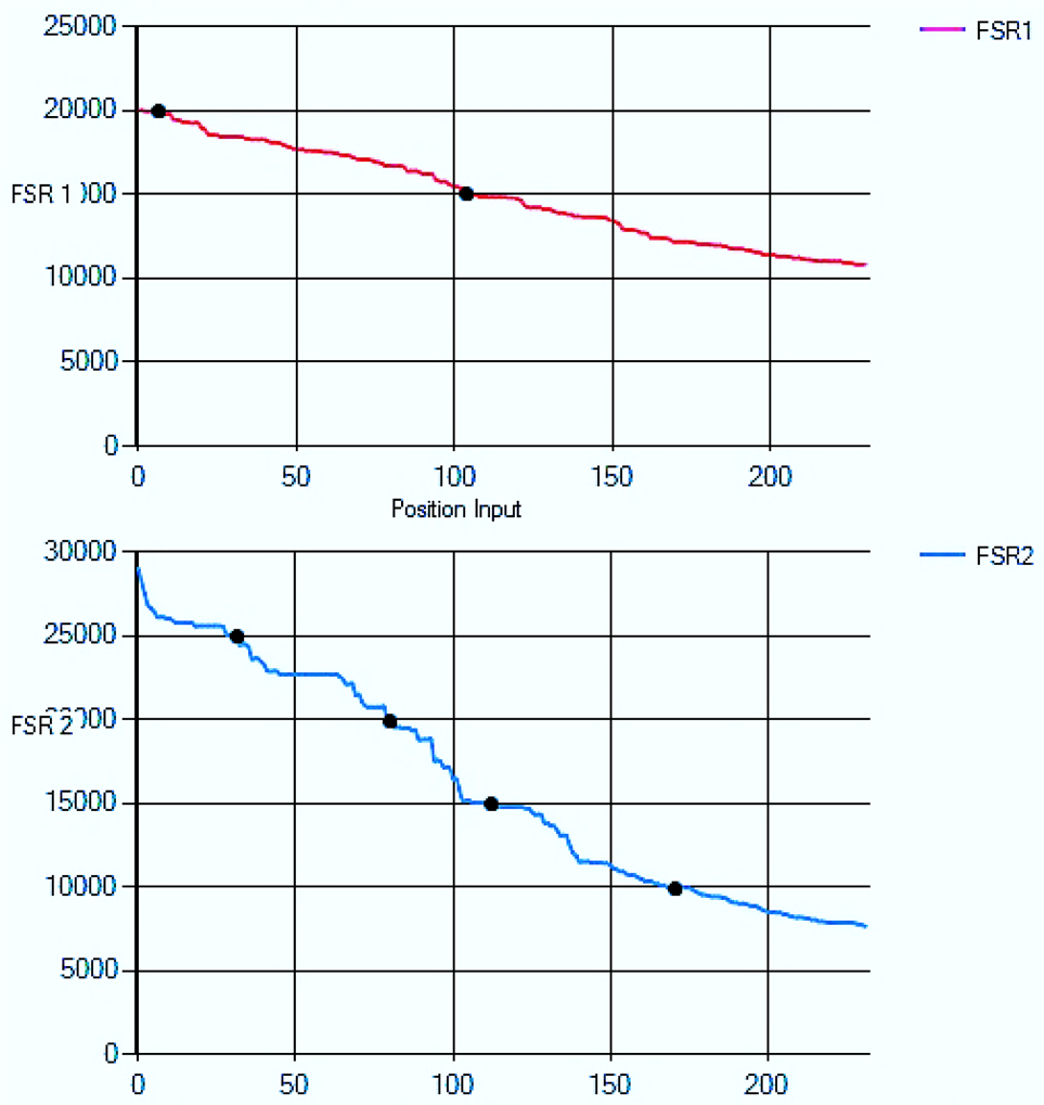
Objects of various strengths were manipulated, with the aim of observing haptic feedback both physically—in the case of the master hardware—and in the form of GUI—in the case of the PC. The gripper is used to grasp the objects, and the embedded force-sensitive resisters are used to measure the force exerted. In order to test the robotic manipulator for surgical purposes, a human finger was used to manipulate the results, since it can be used as both a hard and a semi-hard object, as shown in Figures 16 and 17. Foam was used to observe the behaviour of soft objects and can be seen in Figure 18.
Results for hard objects are obtained by positioning the finger in such a way that the bone of the finger is clutched by the gripper. Positional inputs to the motor of the gripper are specified along the x-axis and y-axis, representing the digital values of the force-sensitive resistors. At zero input, the gripper is fully opened, and the closeness of the gripper's jaws depends upon the size of the object. Similarly, finger tissue and soft foam are used to observe the behaviour of semi-hard and soft objects, respectively.
The slope of the corresponding curves can be found at any point to determine the stiffness of the objects under operation. A linear approximation method is used to validate differences in slope for hard, semi-hard and soft objects. Initial and final points have been chosen in order to evaluate the numerical values of slopes for the curves belonging to FSR1 only. The reason behind choosing these points is their representation of significance decay in their corresponding curves. The slope equation can be written as follow:

where m, x1 x2, y1 and y2 represent slope, initial point on x-axis, final point on x-axis, initial point on y-axis and final point on y-axis, respectively.
For hard objects, values are as follows:


For semi-hard objects, values are as follows:

For soft objects, values are as follows:


From the evaluated slopes, we can see that the decay is sharpest for hard objects, followed by semi-hard and finally soft objects. Furthermore, experiments have been performed on several other objects with different tensile strengths and tactile characteristics. Reliability can be ensured with the help of these experiments over time, by comparing the characteristics of the objects with their corresponding results.

Hard objects

Semi-hard objects
Soft objects
Physical feedback is also provided at the master hardware, along with visual feedback. While grasping the hard objects with the slave end's gripper, the user can feel the same resistive force at the master end's gripper. During object manipulation, the pitch and yaw motors at the master end are driven in opposite directions to the slave ones, creating tactile feedback at the joints. As previously discussed, current sensors at the joints are responsible for precise tactile force replication.
A low-cost, multipurpose generic type of robotic manipulator, with an emphasis on surgical procedures and equipped with haptic feedback, has been designed and developed. A master-slave topology is used to avoid fatigue and excessive time consumption during usage. PSoC is used to implement a control mechanism, a communication linkage and an embedded system. A dual-loop PI control is implemented to help overcome the problem of backlash in the actuators. Force and tactile feedback is replicated by the master's gripper, yaw and pitch movements, using current sensors on the corresponding joints. These three motions are derived via the master hardware controller, and other motions are activated through a PC. Experimental results were also obtained at the gripper end to ensure the scalability and validity of the overall system.
This system could be extended from wired to wireless communication between the two ends. The PSoC kit has integrated wireless modules to perform such a task. The master end could also be expanded to cover all motions of the slave end. From a surgical robotics point of view, it could be made into a wearable system for the surgeon's hand, to replicate all the required motions for a surgical procedure.
Footnotes
7.
The authors would like to thank the Ministry of Information Technology, Government of Pakistan, National ICT R&D Fund (1779231) and the National University of Sciences and Technology, Pakistan for supporting this research project's completion. This article is a revised and expanded version of a paper entitled “Low Cost Tactile, Force and Size Feedback System for Surgical Robotics”, presented at the 2012 IEEE International Conference on Innovative Engineering Systems (ICIES), Alexandria, Egypt, 7–9 Dec. 2012. 2012”.