
Abstract
This research develops a gravity compensation method that determines the mass of a task object easily and compensates for the external force caused by the task object when it is conveyed by a hydraulic teleoperation construction robot. Moreover, this study establishes a master–slave system for this robot; two joysticks act as the master, and an excavator with four links (fork glove, swing, boom, and arm) represents the slave. To compensate for the influence of gravity, a previous gravity compensation method is proposed and applied to the boom and arm. However, it is ineffective during the conveyance process especially when the task object is heavy because the driving force is influenced by gravity of the task object. Therefore, this research presents a gravity compensation method that can effectively determine the mass of a grasped object and compensate for the external force induced by its gravity, as verified through pressing, grasping, and conveying experiments.
Introduction
In a master–slave system, a human operator manipulates joysticks to govern the remote robot’s positions, velocities, and contact forces with the environment. Thus, this master–slave system enables the operator to perform given tasks remotely and successfully. In recent years, master–slave systems have been sufficiently studied, and these studies have been motivated by various applications, 1 such as space explorations, 2 underwater explorations3,4 and mining, 5 and surgeries6–8 as well as applications in dangerous environments, such as nuclear power plants. 9 In these applications, the human operators need enough information about the slave systems and remote environments to feel physically present at the remote sites. 10 This condition of teleoperation is typically referred to as telepresence. If the slave side transmits correct and sufficient signals back to the operator in a natural way, the effect of telepresence can be immersive. 11 It can be achieved through a variety of feedback signals which flow from the remote environments to human operators, 12 such as haptic feedback,12,13 force feedback,14,15 and visual feedback. 16
Robotic systems need to resist gravitational torques generated by the masses of links, thus actuators can be smaller after gravity compensation method is proposed.
17
Mechanical solutions of gravity compensation method including compensation by counterweights, springs, and auxiliary actuators can resist most joint torques. However, mechanical solutions are not sufficient when joint angles are changed, especially when robots are grasping objects. In this condition, operators need to overcome more reaction torques to manipulate the joysticks. Many methods in the literature were performed with gravity compensation to achieve precise control performance.18–20 A hybrid method to achieve gravity balancing of a human leg over its range of motion is proposed in Banala et al.
21
Incomplete gravity compensators for a 4-degree-of-freedom (DOF) humanlike manipulator are treated in Kim and Cho.
22
The stability and regulation performance of the closed-loop system when the compensation for the gravitational torque is provided by a non-collocated controller is studied in Liu and Chopra.
23
Some researchers
24
consider the estimation and compensation of the gravity force and static friction for robot motion control. In Yamada and colleagues,25,26 velocity-driving force characteristics of links
In teleoperation systems, the slave-side robot should interact with the environment, such as grasping or conveying an object and touching or pressing the ground. In our research, when the slave robot lifts and conveys an object in a hydraulic teleoperation construction robot, especially a heavy one, the reaction torque (force) is generated by the gravity of the grasped object; since the operator has to overcome the reaction torque to manipulate the joysticks, he/she will feel tired and inconvenient after a long-time operation.
To compensate for the external force caused by the gravities of links (boom and arm) and the gravity of the grasped object in the hydraulic construction robot, a gravity compensation method is proposed in this research. This method can determine the mass of an object, distinguish the moment the construction robot lifted and released an object in the hydraulic teleoperation construction robot, and provide the operator with a noticeable sense of reaction force during pressing objects by the arm or boom.
The remainder of this article is organized as follows: section “Master–slave system” describes the master–slave system of our research. Section “Gravity compensation of the boom and arm” and section “Compensation for the gravity of an object” propose a method to compensate the external force induced by the gravity of the grasped object and the gravities of links (boom and arm), respectively. Section “Experiment and analysis” describes experiments on grasping and conveyance of heavy objects. Concluding remarks follow in section “Conclusions.”
Master–slave system
Figure 1 shows the schematic of the master–slave system used for the hydraulic teleoperation construction robot in this research. A typical teleoperation system is composed of master and slave sides. As shown in Figure 1, the master–slave system consists of two joysticks (SideWinder Feedback 2 manufactured by Microsoft Co., Ltd.), which act as the master. The construction robot (a commercially available excavator modified based on Hitachi LandyKID-EX5) is the slave. The joysticks enable movements forward/reverse and right/left. Its displacements are detected by position sensors. Each joystick is composed of two direct current motors that enable an operator to sense the grasping of an object by the fork glove and to feel the work reaction force induced by the construction robot. The construction robot is represented by a robot armed with 4 DOFs which consist of four hydraulic cylinders (fork glove, arm, boom, and swing). Cylinder displacement is measured by magnetic stroke sensors embedded in the pistons. Pressure sensors are installed on the cap end and rod end of the cylinder for measuring the pressure. The magnitude and direction of the piston velocity change with the magnitude and direction of the joysticks by the velocity control method. The piston velocity of the hydraulic cylinders is zero when the joystick is in the intermediate position. The control relationship of the construction robot with two joysticks is shown in Figure 2. The operator manipulates the joysticks to control the construction robot as guided by the reaction force to the joystick and the visual prompting on the screen.

Schematic of the master–slave system for a hydraulic teleoperation construction robot.

Illustration of the construction robot and joysticks.
Gravity compensation of the boom and arm
A gravity compensation method, which can eliminate the external force generated by the gravities of the boom and arm, is described in Liu and Quach. 24 Free motion experiments are then conducted on the boom to verify the effectiveness of the parameters by velocity control method with gravity compensation. Object pressing experiments are conducted to confirm that velocity control can provide an operator with a realistic sensation of force feedback when it is applied to the boom and arm.
Gravity compensation method
Kinematics equation of the robot
The gravities of the boom and arm can strongly influence the driving force when the postures of the four links (fork glove, arm, boom, and swing) change on the slave side. The influence of gravities of the swing and fork glove on the driving force is omitted when the postures of the swing and the fork glove vary. The robot arm then obtains 2-DOF by disregarding the swing and fork gloves. In this research, the construction robot is placed horizontally on the ground. Table 1 shows the link parameters. With respect to the relation between the links and cylinders displayed in Figure 3, the joint angles


Link parameters.


Relation between the links and the cylinders.
Dynamic equation of the robot
As shown in Figure 3, the angles between the link and its center of mass are expressed as

where
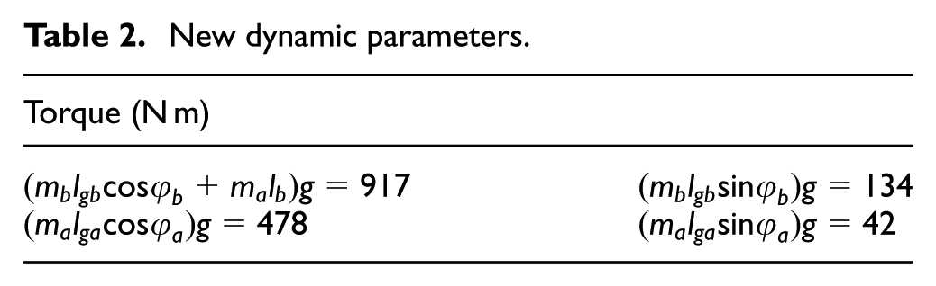
Identification of the dynamic parameters
When equation (3) is used to calculate joint torque, the following dynamic parameters must be derived: the mass values of the links
New dynamic parameters.
Calculation of
and
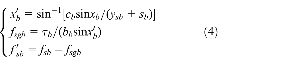
In terms of sine theorem, angle
Experiments and analysis
Free motion experiment on the boom
As indicated in Figure 4, the experimental results confirm that piston displacement varies with
Result of the free motion experiment on the boom.
Reaction torque to the joystick
The reaction torque to the joystick


Pressing experiment
Figure 5 depicts the results of the pressing experiment, which involved the pressing of a soft object (a piece of urethane foam) by the tip of the fork glove. The arm alone was controlled. (A) shows that the construction robot pressed the urethane foam slowly, and (B) indicates that the construction robot stopped pressing when the operator experienced the reaction torque to the joystick during the process. Furthermore,

A piece of urethane foam is pressed by the arm.
Figure 6 depicts the pressing of a concrete block and of a piece of urethane foam, respectively, by the boom. As shown in Figure 6,

A concrete block and a piece of urethane foam are pressed by the boom.
In general, the experiment results prove that the velocity control method with gravity compensation can be applied to the boom and arm and can generate a realistic reaction force for the operator. These findings also confirm that the dynamic parameters are effective and appropriate when the velocities of the arm and the boom are controlled.
Compensation for the gravity of an object
Control of the boom to grasp a heavy object
Figure 7 shows how a fork glove grasps a concrete block (9.7 kg) when the boom is controlled. The fork glove grasped the block in approximately 10 s and released it in roughly 155 s.
Grasping a concrete block through boom control.
Dynamic equation of the robot arm as it grasps an object
When the robot arm grasps an object, it is considered as a system with 2-DOF. Its coordinates are presented in Figure 8. The center of mass of the grasped object is located at the end of the robot arm (the tip of the fork glove), and the length between the center of mass and the joint is


Coordinate system of the robot arm with an object.
Identification of the mass of an object and the calculation of
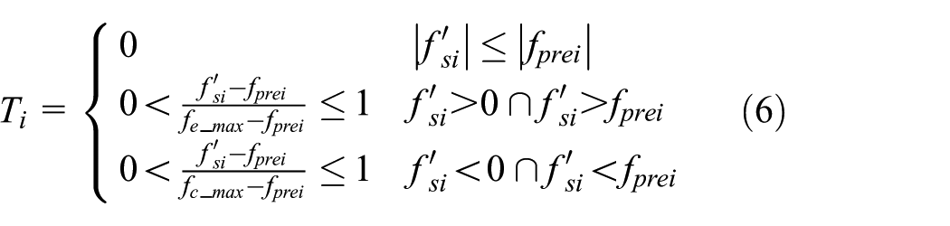
Joint torque consists of two variables, as given in equation (9) The first is generated by the gravities of the boom and arm, whereas the other is caused by the object. Therefore, equation (4) should be modified as in equation (10).

Hence, this research introduces a parameter


Compensated driving and putative forces.
Although


Identification of the mass of an object and the calculation of
Experiment and analysis
Experiment on the grasping of heavy objects
Three task objects whose mass were 9.7, 4.2, and 20.5 kg were placed in area Ⓐ, Ⓑ and Ⓓ, as illustrated in Figure 1. The operator manipulated the construction robot to grasp and lift the task objects one by one using joysticks. The experimental data are shown in Figure 11, in which (A), (B), and (C) represent the process of grasping and lifting three task objects, respectively. The estimated curve in relation to mass of objects,

Grasping of heavy objects when the boom is controlled.
Experiment on the conveyance of heavy objects
The practical process of transferring an object through the construction robot was simulated in a conveyance experiment. The operator manipulated the construction robot to grasp and convey the block using joysticks.
Concrete blocks whose mass were 3.2, 5.4, 9.1, 15.1, and 20.5 kg, respectively, were utilized as task objects, along with an empty tin can (0.4 kg) and one with water (4.0 kg). The total number of task objects is 7. Task objects were placed in area Ⓐ, as illustrated in Figure 1, in descending order by mass, respectively. The conveyance experiment was conducted 7 times by an operator. Six males with a mean age of 26.1 years were enrolled in this research. So, a single task object was conveyed 24 times, as shown in Table 3.
The actual and measured mass of task objects except empty tin can.

SD: standard deviation.
The conveyance sequence was as follows:
First, the task object was conveyed and dropped to area Ⓑ from area Ⓐ.
Second, grasped and conveyed the object to area Ⓓ.
Then conveyed to area Ⓒ;
Finally, returned back to area Ⓐ.
During conveyance, the mass of the empty tin can was zero. This finding can be attributed to the following reasons: Given that cylinders are nonlinear systems in real life, the

Results of the conveyance of heavy objects.
In this research, the experimental results are validated by the NASA–Task Load Index (NASA-TLX), which measures mental strain. NASA-TLX is easy to implement and is sensitive to low mental workloads. 27 It consists of six subscales: mental demand, physical demand, temporal demand, personal performance, effort, and frustration level.
The procedure of NASA-TLX for an operator is expressed as follows:
A pairwise comparison test is conducted to obtain the weight of the six subscales (
An evaluation experiment that is the conveyance experiment mentioned above is executed.
Each subscale is evaluated. After the conveyance experiment, scores,
The mean weighted workload (WWL) score is calculated in terms of equation (15) and recommended based on the evaluation of workload by NASA-TLX. 28 The lower the WWL score, the lower the operator’s mental strain

Figure 13 shows the result of NASA-TLX. In terms of paired sample t-test and p value
NASA-TLX subjective measure.
Conclusion
In teleoperation, an operator must perceive a reasonable sense of force from the construction robot. In this research, the master–slave control (velocity control) method with gravity compensation is applied to the boom and arm. Pressing experiments were conducted, and its results proved that the velocity control method can generate the realistic reaction force for an operator. This research used blocks and tin cans of different mass as task objects, and the gravity compensation method was effectively used to compute the mass of these grasped objects. The effectiveness of this gravity compensation method has been verified through conveying experiments. The experimental results indicate the feasibility of our proposed method.
Footnotes
Academic Editor: Yangmin Li
Declaration of conflicting interests
The author(s) declared no potential conflicts of interest with respect to the research, authorship, and/or publication of this article.
Funding
The author(s) disclosed receipt of the following financial support for the research, authorship, and/or publication of this article: The authors would like to thank the financial support from the National Natural Science Foundation of China (Nos 51575219 and 51305153).