
Abstract
This paper presents two rehabilitation schemes for patients with upper limb impairments. The first is an active-assistive scheme based on the trajectory tracking of predefined paths in Cartesian space. In it, the system allows for an adjustable degree of variation with respect to ideal tracking. The amount of variation is determined through an admittance function that depends on the opposition forces exerted on the system by the user, due to possible impairments. The coefficients of the function allow the adjustment of the degree of assistance the robot will provide in order to complete the target trajectory. The second scheme corresponds to active movements in a constrained space. Here, the same admittance function is applied; however, in this case, it is unattached to a predefined trajectory and instead connected to one generated in real time, according to the user's intended movements. This allows the user to move freely with the robot in order to track a given path. The free movement is bounded through the use of virtual walls that do not allow users to exceed certain limits. A human-machine interface was developed to guide the robot's user.
Keywords
Introduction
Upper extremity paralysis (the inability of a muscle or group of muscles to move voluntarily) occurs as a consequence of lesions such as injuries to the central or peripheral nervous system. Causes of injuries include strokes, sports mishaps and car or occupational accidents, among others. According with the US National Stroke Association®, approximately 80% of stroke survivors experience hemi-paresis, which causes weakness or an inability to move one side of the body. Spasticity affects roughly 40% of stroke survivors and is characterized by stiff or tight muscles that constrain movement [1]. The primary treatment for these cases is rehabilitation, i.e., the process of helping an individual achieve the highest level of independence and quality of life possible, physically, emotionally, socially and spiritually. Where rehabilitation is possible, it involves many hours of highly skilled procedures. The number of people capable of providing such support is insufficient for adequately covering all patients that need help. Recovery progression varies greatly and while certain people recover relatively quickly, for others, recovery can take a long time and can even be a lifelong process.
The use of robotic assistance in rehabilitation is an important point of interest that is attracting significant attention [2, 3]. Many studies have shown that robotic rehabilitation can be effective at improving arm function following a stroke [4–8]. However, in studies where participants received an equivalent amount of either robotic or conventional therapy, the improvements in arm function were no longer significant [8]. One reason for this may be that earlier studies used robotic devices with a limited number of degrees of freedom, such as planar manipulandums. Indeed, a recent study [9] demonstrated a small but significant improvement in arm function following therapy involving a 7-degree-of-freedom robot (shoulder, elbow and hand opening) when compared to an equivalent amount of conventional therapy. Thus, there is a clinical need for continuing the development of robotic devices that can assist with naturalistic arm movements.
The ETS - Motion Assistive Robotic-exoskeleton for Superior Extremity (ETS-MARSE) was developed in our laboratory [10–13] in order to provide rehabilitation assistance for the upper limbs. Currently, it comprises a seven-degree-of-freedom (DOF) exoskeleton, designed to cope with the full motion capabilities of the human arm; that is, at the shoulder, elbow and wrist levels, combined or individually. Additionally, it contains a graphical user interface that uses a virtual environment with different rehabilitation exercises. To date, work in this regard has been developed to the point of passive rehabilitation, which means that the exoskeleton executes movements along predefined trajectories, while moving the subject's arm with it to help improve the range of movement. This paper describes the next rehabilitation step: active-assistive and active rehabilitation [14–16].
The methodology presented in this paper combines the advantages of the trajectory tracking control as the inner loop control of the robot and an admittance-based trajectory modifier that performs the outer force control, and which is responsible for the interaction between the robot and user. The admittance is used as a means of modifying the desired trajectory [17, 18]. Due to the nonlinear nature of the ETS-MARSE, a nonlinear control technique that has inherent adaptive characteristics has been used, i.e., virtual decomposition control (VDC). VDC is a relatively new approach that can reduce the mathematical complexity of multi-degree of freedom robots and has an adaptive nature that helps to deal with different patients' dynamics [19]. As robots become more complex, the computation of robot dynamics is proportional to the fourth power of the number of DOF in Lagrangian dynamics [20]. VDC uses the dynamics of virtually created subsystems to conduct control design; this decomposition yields simpler dynamic equations in formulation and implementation [21]. In previous research with ETS-MARSE, we used different non-linear control strategies, such as computed torque (CTC) [10] and sliding mode control (SMC) [12]. Though SMC performed well, it showed an approximately 1.5 times increase in end-effector tracking error when conditions of the subject changed and perturbations were presented, while the same exercise was performed. It also presented the associated chattering, which can be reduced but not eliminated [12]. Conversely, an advantage of the VDC lies in its inherent adaptive capabilities, in the form of internal parameter estimation. It was shown in our previous studies that in direct comparison with CTC and PID, VDC can successfully cope with the physiological variations between different subjects [22]. Although differences in tracking error were minimal and below the needs dictated by the application, PID showed an average RMS error standard deviation more than three times larger than for VDC; for CTC, this was more than 10 times that of VDC. VDC however, due to control gains and parameter estimation gains, involves a complicated process of initial tuning during the controller design process.
In order to obtain the user's motion intention and modify the robot's trajectory tracking accordingly, the admittance concept is used. This approach has also been proven adequate for high ratio transmissions systems [18, 23]. The robot takes information from the human-machine interaction, in this case through contact force feedback between the structure and the person's arm and uses it to actively modify its rehabilitation task.
In recent years, admittance control for rehabilitation has come to represent a well-known approach and different schemes have been proposed [17, 24–26]. One of the main advantages of this type of control is that it offers the possibility of active rehabilitation. This is because it contributes to the rehabilitation process by allowing task repeatability and provides relevant data for the quantification of different outcomes, such as improvement, effort, etc. However, this approach is limited by the number of degrees of freedom of the robotic device [24] or has only been employed with end-effector type robots [17, 25, 26]. The contribution of this paper is to present both active-assistive and active rehabilitation task schemes for the 7DOF ETS-MARSE exoskeleton. These tasks are based on path-tracking game-like exercises that have been successfully employed in neuromuscular rehabilitation [27]. The rehabilitation robot works in two different scenarios, both of which make use of a virtual environment as an interface to visualize the movement to be performed. En the first scenario (active-assistive rehabilitation), the robot follows a predefined movement path; however, the system measures the user's force opposing the predetermined movement and allows a certain adjustable degree of trajectory variation. In the active mode, the robot allows the user to freely move in the workspace while trying to achieve a target. In this case, the user's movement is constrained by means of virtual walls that restrain him from exceeding certain limits and mark the point where the system will take corrective or assistive actions to help resolve a collision conflict. At all times, the robot appears weightless to the user and helps to support their arms if they stop in the middle of an exercise. These schemes may encourage the patient to actively participate in the exercise by attempting to follow the target trajectory and motivating them to improve their level of accomplishment.
This paper is organized as follows: section 2 describes the ETS-MARSE and the setup of the system. In section 3, a general description of the controller (VDC) is given. In section 4, the implementations of the active-assistive and active rehabilitation schemes are described. Section 5 summarizes the experimental setup and presents the results. Finally, section 6 provides conclusions and future work perspectives.
System Overview
The exoskeleton robot arm ETS-MARSE is shown in Figure 1. It is an open chain, all-revolute, 7DOF wearable manipulator-like robot; its joints were designed to correspond to the principal degrees of freedom of the human arm. These are:
3DOF at shoulder level for horizontal flexion/extension, vertical flexion/extension and internal/external rotation
1DOF for elbow flexion/extension
1 DOF for forearm pronation/supination
2DOF at the wrist level for radial/ulnar deviation and flexion/extension
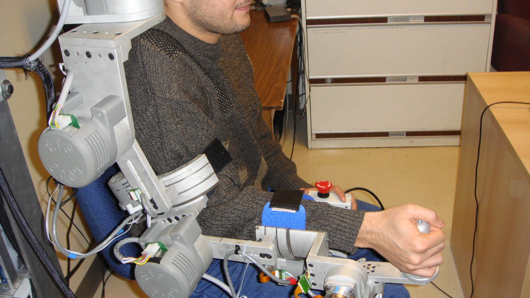
Subject wearing the ETS-MARSE robotic arm
The exoskeleton structure has a six-axis force sensor mounted on the end-effector (tip) of the robot, which is at the base of the handle where the user's hand must be positioned. Each joint is driven by a brushless DC motor that has a Hall effect sensor used for position feedback of the joints. The motors are incorporated with harmonic drives; the specifications for the motors and harmonic drives can be found in Appendix A. A backplane card collects analogue and digital signals and connects through the proper interface cards to an NI PXI-7813R (remote input-output card) placed on an NI PXI-1031 chassis. The card has an integrated FPGA in which low-level control is performed, a PI controller for the current loop of the motors, position feedback via the Hall effect sensors and the collection of force sensor inputs. A PXI-8108 controller, which performs high-level control (the robot operating system and the trajectory tracking controller) is also mounted on the chassis. In this case, we are using the nonlinear control technique known as virtual decomposition control (VDC) [19], with an update rate of 1 ms. A description of the implementation of the VDC is outlined in section 3 of this paper.
A PC runs the human-machine interface virtual environment in which the robot wearer visualizes the rehabilitation exercise. The current architecture of the system is depicted in Figure 2. Since the system is a human-machine interface, safety is a major concern and for this reason, a hardware emergency stop button is built into it.

ETS-MARSE system hardware overview
The control technique we used is presented in this section, but only the steps required to implement VDC are listed. This technique presents an effective approach for dealing with high DOF robots and multi-robot control. A detailed analysis is beyond the scope of this paper; readers interested in such an analysis are referred to other works that address this technique [28, 29]. The frame attachment for the DOF of the ETS-MARSE, following the method summarized in [30], is shown in Figure 3. The resulting Denavit-Hartenberg modified parameters are obtained, as described in [30] and are summarized in Table 1.
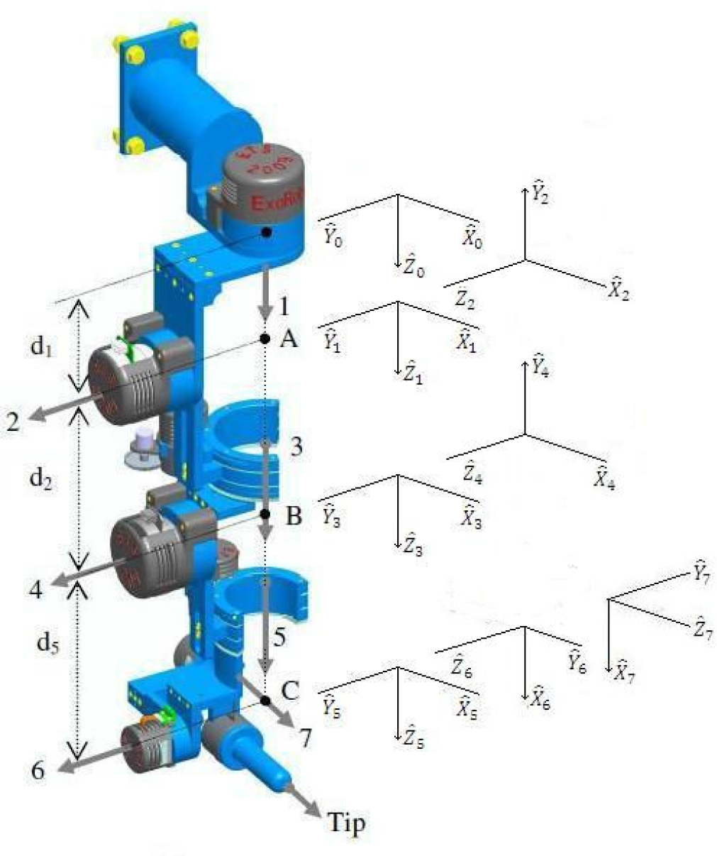
7DOF exoskeleton robot arm
ETS-MARSE Denavit-Hartenberg modified parameters

The first step in the VDC analysis covers the virtual decomposition of the robot; in our case, we can view the exoskeleton as a single open chain. This results in decomposition into fourteen subsystems, as illustrated in Figure 4.

Virtual decomposition in 14 subsystems
From the resulting parameters shown in Table 1 and the decomposition shown in Figure 4, the homogeneous transformation matrices of the system are obtained. From these, the force/moment transformation matrices of the robot are calculated as follows:

where A R B represents the rotation matrix from one frame to the next and A r AB is the distance between frames, and:

where A r AB (i) represents the i th term of the A r AB vector.
We calculate each force/moment transformation matrix
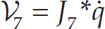
The next step is to calculate B i V, the linear/angular velocity vectors of the B i frames (with i = 1, …, 7) as follows:

where B i v is the linear velocity vector and B i ω is the angular velocity vector of the corresponding frame. With the previous linear/angular velocity vectors, the augmented velocity vector is formed as:

Equation (4) can be written in the following form:
where

with z = [0 0 0 0 0 1] T , I7 is a 7 × 7 identity matrix and 06 a 6 × 1 zero vector.
Finally, the required velocities need to be calculated as a function of the control requirements. Since in our case the robot is required to track a control trajectory, we incorporate the desired position in the vector of required velocities:

where

In this paper, only the inverse dynamics that take part in the control of the robot are described. To obtain the inverse dynamics, it is necessary to calculate the forces required for the links and then the torques required by the joints. The first step for the link dynamics is to obtain the required net force/moment vectors using the following equation:
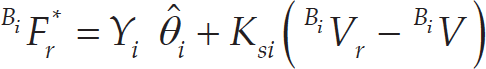
for i = 1, …, 7, where K
si
is a symmetric positive-definite gain matrix; the velocities
B
i
V
r
and
B
i
V are defined in relations (3) and (8), respectively;

for i = 1, …, 7 and ³ = 1, …, 13. Where

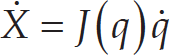
The projection function P is a differentiable scalar function defined for t ≥ 0, such that its time derivative is governed by:
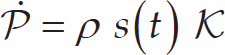
with:
Once this step is completed, the required force/moment vectors at the cutting points are obtained as follows:


for i = 6, …, 1. The next step is the calculation of the dynamics of the joints. Some relations and variables used to calculate the dynamics of the joints were also used in the calculation of the dynamics of the links; therefore, a sub-index, a, is used to refer to the joints' dynamic equations and variables. For i = 1, …, 7 in (14) to (18), the following vectors are defined:


where J mi is the equivalent mass or moment of inertia, k ci > 0 denotes the Coulomb friction coefficient, k vi > 0 denotes the viscous friction coefficient and c i denotes an offset that accommodates asymmetric Coulomb frictions. As in the case of the links, the estimation of the parameters defined in (15) is performed as follows:

However, in this case, ³ = 1, …, 4 and the scalar function s is defined for the joints as:

Thereafter, the net torque for the joint becomes as follows:

where k ai denotes a feedback gain.
Finally, the torques obtained from the link and joint analyses are combined. First, we extract the torque of the link force/moment vector.

for i = 1, …, 7. With z defined after (6), the control torque is then designed for i = 1, …, 7 as:

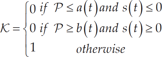
For a complete stability analysis of VDC, the reader is referred to [19, 28, 31]. Figure 5 presents a flow diagram of the VDC architecture applied in the inner position control loop. The interaction between the robot and the human is represented by the human joint position q h , causing the robot to exert torque τ h . The human also applies force, ℱ, which will be used in the outer force control loop, as described in the next section.
Block diagram of the VDC
In robotics, a trajectory defines movement of a robot in a multidimensional space. This trajectory contains information concerning the position, velocity and acceleration for each degree of freedom in time [30]. To control the movement of the robot, the user defines a desired trajectory that includes this information and is usually generated by means of a trajectory planner.
Trajectory Planner
The trajectory planner for ETS-MARSE is based on joint-space specification. It is performed in real time on a dedicated processor (PXI-8108), described in Section 2. Some exercises can comprise different trajectory segments, each specified by initial and final positions for each joint. Each segment of the trajectory for each joint is calculated using a cubic polynomial [30] of the form:

where a i for i = 0, …, 3 are the coefficients of the cubic polynomial to be specified. With initial and final velocities of zero, the initial position defined as q(0) = q0 and the final position defined as q(t f ) = q f , equation (21) reduces as follows:

In order to obtain information on the velocity and acceleration of the trajectory, the corresponding first and second derivatives of (22) are used.
In rehabilitation, it is often useful to specify a desired trajectory in Cartesian space in order to specify movements with a physical interpretation. This can be as simple as a straight line, or, for example, following a geometrical shape such as a triangle, a rectangle, etc. In the case of the ETS-MARSE robot, the trajectory can be specified either in the joint space or in Cartesian space (robot workspace); whatever the case, the trajectory tracking is always executed in joint space. Thus, it is necessary, given a position and orientation of the end-effector in Cartesian space, to find the joint positions of the robot that can accomplish this desired configuration (inverse kinematics problem). In this case, the pseudo-inverse of the Jacobian method is used.
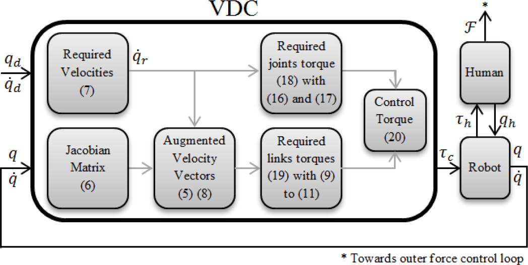
In the dynamic relations of the links of a robot, the reference frame of each link has linear and angular velocities, with respect to the other links and to the robot reference frame. The Jacobian matrix of a robot relates the joint velocities with linear and angular velocities of the Cartesian space as follows:
where

where J(q)+ = J(q) T (J(q)J(q) T )−1 is the generalized pseudo-inverse. The method can be enriched by adding null space characteristics to the right side of the equation with the term (J(q)+ J(q)-I)ξ, where ξ ∊ ℝ n is an arbitrary vector that can be used for tasks such as obstacle avoidance and I is the 6 × 6 identity matrix. Being a redundant robot, the ETS-MARSE has different solutions for its inverse kinematics problem; currently, to solve that problem, we are developing an inverse kinematics solution (analytical, geometrical or numerical) that will ensure anthropomorphic configurations, as in [17, 33]. In the rehabilitation tasks presented here, solving the null space is not necessary, since only predefined Cartesian trajectories were used. These trajectories were simulated and tested to constantly ensure a configuration of the robot not presenting any non-ergonomic positions. Additionally, singularity avoidance is secured with joint angle limits, both in software and hardware (mechanical stoppers).
In the case of active-assistive mode, the robot helps the user, at an adjustable level, to achieve the tracking of a trajectory shown in the virtual interface. To do this, the assistive controller somewhat modifies the predefined trajectory in relation to the patient's movement limitations. The system measures the force exerted by the user at the end-effector of the robot, which can be interpreted as the difference between the user's trajectory and the goal trajectory.
The first step is to transform this information into a quantity that specifies how the subject's opposition force affects all the DOF of the exoskeleton (that are related to the human arm joints). As a consequence of the virtual work principle, the Jacobian matrix relates static forces, i.e., it transpose assigns Cartesian forces to joint torques as follows:

where τ is the 7 × 1 vector of joint torque and ℱ is the 6 × 1 measured force-moment Cartesian vector. This relation gives us the user's opposition force in terms of joint torques.
The second step is to transform these torques into meaningful information for the trajectory that is being followed, that is, information relating to changes in position. Impedance can be defined as a transfer function between the external force acting on the manipulator and its displacement [34]. Knowing the result from (25) and applying the impedance definition in the form of an admittance relation, which directly relates an input force to an output position, we have a direct form with which to modify the desired trajectory as follows:
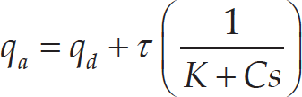
where q a is the 7 × 1 vector of the new desired trajectory defined by the admittance, q d is the 7 × 1 vector with the original desired trajectory from the trajectory planner and the final right term of the equation in the parenthesis, the chosen admittance function. It can be seen that the latter has the form of a spring-damper function, in which τ is the 7 × 1 vector of torques exerted on the robot's joints by the subject, calculated from (25) and K and C are the 7 × 7 gain matrices corresponding to the spring and damper constants, respectively. By adjusting these constants to provide higher or lower opposition to the subjects' disturbances and constraints over movement, this admittance function allows for variation in the amount of help to be provided by the robot. This particular admittance function by means of the damping term also provides smooth movement.
Another application of an admittance function modifying a predefined trajectory involves performing a free trajectory movement. If the spring-damper system introduced by the admittance function in (26) is detached from a desired trajectory, it becomes a means of moving the robot freely within its workspace. In this case, the subject is allowed to move in the environment presented by the virtual interface and can try to follow the trajectory without any robotic aid. This rehabilitation option, corresponding to active (unassisted) rehabilitation, is achieved by changing the desired trajectory of the robot, that is, q d in (26). Instead of coming from a trajectory planner, the desired trajectory comes from the robot's previous position, as follows:

where q is the 7 × 1 vector of the joint positions. If the user stops exerting forces on the force sensor, τ → 0, causing the robot to reduce its movement and gradually, when q a = q, the robot remains in its most recent position. With this mode, the robot is allowed to follow the user's movements, while the trajectory tracking ensures the weightless sensation of the robot structure to the subject and provides gravity compensation. In Figure 6, a block diagram showing the control architecture is presented. The position of the selector shown in the bottom row of the system corresponds to the case of active-assistive rehabilitation (left position) and active rehabilitation (right position) described earlier. In this case, the desired trajectory that inputs the VDC (see Figure 5) is the admittance modified trajectory q a from (26) or (27) and Δ q is the second term of the right-hand side of the same relations.

Block diagram of the system
The ETS-MARSE works in two different active rehabilitation modes, which use virtual walls added to the environment in order to constrain movement to a confined space. In the first mode, the system restrains movement beyond the wall and only allows movement that corrects the collision situation, i.e., the robot will not allow the user “to slide” through the wall to complete the exercise. The user must return to the inner part of the space in order to continue with the movement. The algorithm used in this rehabilitation mode is presented in Figure 7. The second mode of operation is intended for users that need more assistance once there is a deviation from the main trajectory. Once the user hits a wall, the robot stops for a predetermined time to let the user notice that movement has been stopped by the system. It then goes into passive mode, which means that the robot will help the user by returning automatically to the closest point on the desired trajectory, as illustrated in Figure 8. Here, Pw represents the point where the user hits the wall, Pi the trajectory initial point, Pf the final point and Pr the point of the position reset. The last one, the closest point to the trajectory, is obtained as follows: first, the cosine of angle α is calculated:

Active rehabilitation with walls

Virtual wall collision and reset path

where u ∊ ℝ3 and v ∊ ℝ3 are the direction vectors of the lines

With the final point obtained from (29) and the initial point as Pw, the passive mode of the system conducts the robot end-effector to this point by means of a trajectory generated as described in subsection 4.1. Finally, after another predetermined time to allow the user to be ready, the system allows them to continue. The algorithm followed by this rehabilitation mode is presented in Figure 9.

Active-assisted rehabilitation with walls
In this section, we present one scenario for each of the two rehabilitation modes. The first comprises an experiment performed for active-assistive rehabilitation and the second, two tests for active rehabilitation.
Active-assistive Rehabilitation
This first scenario comprises three tests based on a tridimensional square trajectory, defined below. The trajectory involves the movement of the seven degrees of freedom of the robot. Test number one is given as a reference of the behaviour of the robot, i.e., without modifying the trajectory tracking. This scenario corresponds to the passive rehabilitation mode in which the patient is guided through a predefined rehabilitation exercise. The result of this test is shown in Figure 10. It can be seen that the tracking error is very small and this will be used as a reference value. The initial position of the end-effector of the robot corresponds to point A; it moves to points B – C – D and then returns to A. The points are listed in Table 2.
Robot active-assistive rehabilitation reference trajectory

Robot active-assistive rehabilitation reference trajectory

Reference trajectory tracking
The next two tests constitute the central point of this approach of rehabilitation (active-assistive). In these cases, the tracking is modified based on the measurements of the force sensor. The reference trajectory is the same as that presented in Figure 10, but modified according to equation (26). To simulate stiffness or spasticity from the user, an elastic band is tied from the handle of the robot (which holds the force sensor) to an external anchor point. This provides a systematic comparison, depending only on the modification of the admittance parameters. The setup allows the variation to be independent from the test subject, whose behaviour can change from one test to another. For the first test, the admittance parameters were selected to provide a high degree of help, specifically with the main diagonal of K = [0.05 0.06 0.06 0.05 0.02 0.02 0.02] T and the remaining elements equal to 0, and the main diagonal of C = [5 1 5 10 5 5 5] T . The remaining elements were also zero. The second test was configured to provide a low degree of help from the robot, i.e., with the main diagonal of K =[0.1 0.12 0.12 0.1 0.04 0.04 0.04] T and the main diagonal of C = [5 1 5 10 5 5 5]T, and the remaining elements being zero.
The results of these tests are shown in Figures 11 and 12 for high and low degrees of help, respectively. Because the opposition force to this movement is exerted on the robot, the actual trajectory is deflected from the predefined one. In these figures, the dotted line represents the desired trajectory and the solid line the actual trajectory followed by the robot, which was perturbed using the elastic band.

Trajectory modified with a high degree of help
For the final two tests (Figures 11 and 12), the force and torque measured with the force sensor are shown in Figure 13. We can see how the force input from the elastic band is very similar in both tests; nevertheless, the modification of the trajectory is different, allowing us to see the effects of modifying the admittance function coefficients.

Trajectory modified with low degree of help

Comparison of forces-torques between high and low degree of assistance from the robot
In this rehabilitation mode, the user follows the trajectory by means of a virtual interface that provides the tracking of movement and incorporates a variety of exercises in a game-based environment. The active rehabilitation mode with virtual walls has two different tests: the first with the wall as an obstacle and the second, where collision with the wall indicates that the robot will assist the user, as described in section 4. Both setups require the subject (32-year old healthy male subject with a mass of 91 kg and height of 182 cm, in seated position) to track a straight line; the virtual wall is located parallel to the desired trajectory, 10 cm to the right.
The result for the first experiment is shown in Figure 14. In this mode, once the user hits the wall, the system only allows movement towards the desired trajectory. In the plots at the bottom of the figure, the filtered force in the Y-axis of the force sensor and the position of the end-effector in the Y-axis of the reference frame are shown as a function of time. Both axes are the Y-axis, because the wall is set in the Y-direction. The Y-axis of the force sensor is parallel to the Y-axis of the reference frame, but in the opposite direction, which provides a good reference point for the comparison. Nevertheless, it is very important to remember that the force and its modification follow the transformation described in (25) and (27). It can be seen that, when the subject starts to apply force to the sensor at 12.86 seconds, the displacement of the robot starts. At 17.05 seconds, the wall is hit; the virtual wall restricts the movement of the end-effector beyond this point (at approximately 0.08 m), irrespective of an increase in the user's produced force. Finally, at 20.40 seconds, when the user starts to apply force in the opposite direction (away from the wall), the system allows the robot to continue with the movement and completes the exercise.

Virtual walls as obstacles for active rehabilitation
The final test shows the assisted wall return. It can be seen in Figure 15 that the user starts the movement by applying force to the robot at 8.31 seconds. Once the wall is hit, at approximately 10.90 seconds, it can be seen that the movement of the robot stops, even though force continues to be exerted for some time. The system, after an idle waiting time (three seconds), resets the position to the closest point in the trajectory (two seconds), followed by another idle time (three seconds), allowing the user to be ready. After this, the user can continue the exercise when ready, in this case, at 20.06 seconds. It is important to note that in the two idle states and in the reset state, there is no input from the user to the force sensor. This shows that assistance is provided for the system without any action needed from the user. The small delays that can be observed in the state changes, especially from the applied force to the start of movement, are due to the time it takes to overcome the static friction and the filtering in the force sensor's raw data; this delay is imperceptible to the user.
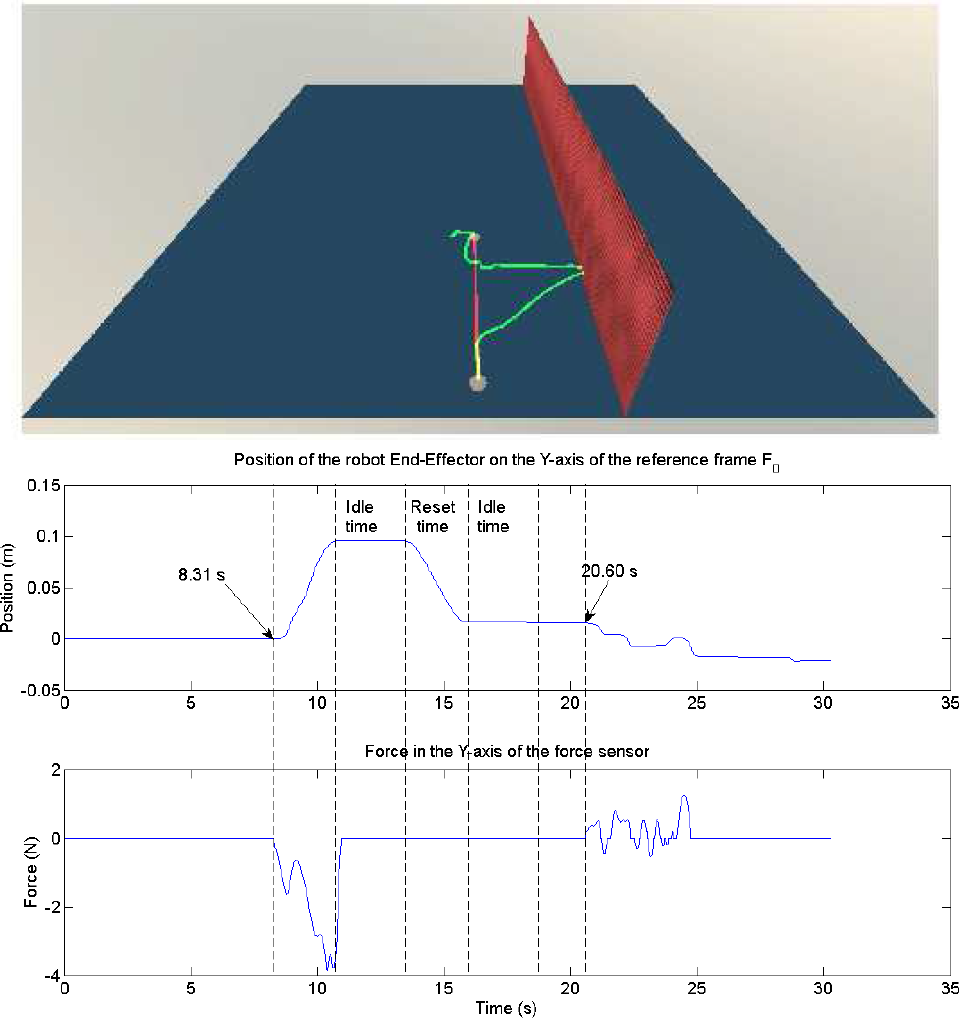
Virtual walls as obstacle and starting point for robotic assistance in active rehabilitation
The experimental results confirm that the present work can actively help in different rehabilitation scenarios. For active-assistive rehabilitation, with the guidance of the ETS-MARSE, a subject can accomplish a specified trajectory. The robot can vary the assistance provided according to the evolution and the needs of future patients. It is important to note that the robot will not produce forces that are beyond the capabilities of the subject in order to fulfil a trajectory. A qualified therapist must adjust the limits according to the user's requirements. The amount of variation of the trajectory can be quantified as an excellent measurement of progression of the subject. In the case of active rehabilitation, it is shown how by means of the same admittance function, the system can work in a free movement mode. This rehabilitation mode, combined with limits (virtual walls), could indicate when patients will need assistance from the robot to complete their rehabilitation tasks. As the next step for active rehabilitation, the system will incorporate the use of electromyographic signals in order to complete the readings of the force sensor and to provide better tracking of the subject's movement intentions, and will be used on its own for subjects where the force sensor may be not enough to determine the intended movement.
Footnotes
7.
Cristóbal Ochoa Luna would like to thank the National Council on Science and Technology of Mexico (CONACYT) for the support under grant No. 211951.
This article is a revised and expanded version of a paper titled “Robotic assisted trajectory tracking for human arm rehabilitation,” presented at the 2014 International Conference on Mechatronics and Robotics, Structural Analysis (MEROSTA 2014) in the session: Advances in Robotics, Mechatronics and Circuits. Santorini, Greece, 2014.
Appendix A
The motors and harmonic drives specifications are listed in Table 3:
Appendix B
The 13 elements of parameter vectors θ A ℝ13 are listed as:
where mA is the mass;