
Abstract
Several factors may prevent post-stroke subjects from participating in rehabilitation protocols, for example, geographical location of rehabilitation centres, socioeconomic status, economic burden and lack of logistics surrounding transportation. Early supported discharge from hospitals with continued rehabilitation at home represents a well-defined regimen of post-stroke treatment. Information-based technologies coupled with robotics have promoted the development of new technologies for telerehabilitation. In this article, the design and development of a modular architecture for delivering upper limb robotic telerehabilitation with the CBM-Motus, a planar unilateral robotic machine that allows performing state-of-the-art rehabilitation tasks, have been presented. The proposed architecture allows a therapist to set a therapy session on his or her side and send it to the patient’s side with a standardized communication protocol; the user interacts with the robot that provides an adaptive assistance during the rehabilitation tasks. Patient’s performance is evaluated by means of performance indicators, which are also used to update robot behaviour during assistance. The implementation of the architecture is described and a set of validation tests on seven healthy subjects are presented. Results show the reliability of the novel architecture and the capability to be easily tailored to the user’s needs with the chosen robotic device.
Introduction
Stroke is one of the main causes of disability in adults worldwide, 1 and its rapid growth 2 has revealed the need of new technologies for promoting effective, cost-efficient stroke rehabilitation. Early supported discharge (ESD) from hospitals with continued rehabilitation at home is known to be a well-validated regimen for post-stroke rehabilitation. 3 It consists of services that aim to accelerate the discharge of patients after a stroke event and provide a comparable rehabilitation level at the patient’s home with conventional hospital care and discharge. 4
The application of this regimen to post-stroke rehabilitation has fostered a growing interest in the development of new technologies for telerehabilitation, able to provide remote delivery and monitoring of rehabilitation services over telecommunication networks and Internet. Furthermore, telerehabilitation can also benefit from the recent advancements of robot-aided rehabilitation, thus providing interactive, repetitive and task-specific activities that can be tailored to the user’s needs, and promote motor learning, exploiting neuroplasticity, without the continuous oversight by a therapist.5–7
Many studies have demonstrated the effective role of robots in upper limb robot-aided motor therapy;8–12 conversely, a few studies have investigated the feasibility and the efficacy of remote robot-aided rehabilitation.13–16 The concept of combining telerehabilitation and robot-assisted therapy represents a novel challenging approach in neurorehabilitation; such a concept shows the potential to provide cost-effective and consistently high-quality treatment to patients with limited access to rehabilitation clinics because of location or availability of treatment. 17 In particular, task-specific neurorehabilitation using robotics coupled with ESD approach can significantly improve the field of rehabilitation and yields considerable benefits for patients with stroke impairments.4,18
In the recent years, different telerehabilitation systems have been developed to improve patients’ activities of daily living in the attempt to increase their independent living at home.19–22 The systems for robot-aided telerehabilitation can be grouped into two different classes: systems in unilateral configuration and systems in bilateral configuration. 18
In unilateral configuration only the patient is connected to the robot, while the therapist can remotely communicate with the robot and the patient. The communication between patient and therapist is not required to be real time; after a predefined time-lapse, data are sent to the therapist interface in order to verify the therapy progress and, possibly, modify the treatment.
There are many examples of unilateral robotic systems; they are briefly reported in the following. TheraJoy and TheraDrive are a force reflecting joystick and force reflecting wheel, respectively, that are used together with UniTherapy, a customizable universal software platform for delivering upper limb robotic therapy. 23 The JavaTherapy system 13 is a wrist trainer system based on a low-cost commercial force feedback; it is designed for home therapy and is remotely monitored and managed by therapist via a low-cost web camera and teleconference software. The assisted movement with enhanced sensation (AMES) robotic device 24 enables wrist or ankle exercises in home settings; it is able to provide vibratory sensations to the antagonist muscle-stretching tendon, while the agonist muscle is performing the desired action. The Rutgers Master II (RMII), developed by Popescu et al., 25 is used to increase hand strength in stroke patients using teletherapy. The virtual driving environment 26 consists of an immersive virtual environment with which the patient can interact through various kinaesthetic interfaces, such as a commercial force feedback steering wheel used in gaming applications.
The Hand Mentor™ and Foot Mentor™ are unilateral configuration systems, developed by Kinetic Muscles Inc., that provide hand and foot in-home rehabilitation. The ReJoyce system, developed by Hometelemed Inc., represents an arm-hand workstation designed for clinic and home therapy. In addition, the Habilis platform developed within the Clinical Leading Environment for the Assessment and validation of Rehabilitation Protocols for home care (CLEAR) project 27 is a web-based interoperable platform allowing transmission of multimedia files to assign remotely telerehabilitation sessions to patients affected by stroke, spinal cord injury (SCI) and chronic diseases. Finally, the Hand Mentor Pro (HMP) has been validated through clinical studies;17,28,29 no significant differences were found between home robotic telerehabilitation and standard home exercise programme.
In the bilateral configuration, both the patient and therapist interact with a robot and communicate over the Internet through a shared virtual environment (SVE), normally using a client/server approach. The communication is real time and enables the therapist to modify the current exercise or apply corrective actions during the tasks.
In the work by Basdogan et al., 30 a cooperative ‘ring on a wire’ task over a local area network (LAN) using two PHANTOM™ haptic devices (SensAble Technologies Inc., Woburn, MA) has been performed. Similarly, a LAN-based system has been developed by Goncharenko et al. 31 in order to simulate a dual-arm haptic interaction with a steering wheel. Alternatively, researchers at the MIT Touch Lab and University College London used a peer-to-peer architecture to perform a ‘transatlantic’ touch experiment in which a virtual box was lifted using PHANTOM™ haptic devices. 32
Independent of the type of configuration, studies on ESD have showed the need of in-home rehabilitation delivery system because, when therapy is maintained constant and intense, an increase in the functional recovery can be significant. 33 However, robots for telerehabilitation have to address specific requirements related to the application, such as portability and, consequently, lightness, compactness, easiness to set up and ready to use both for therapists and patients. Furthermore, communication architecture has to be reliable guaranteeing robust and safe communication between the patient and the therapist side. In addition, system modularity is also required since different signals and modules could be employed.
This article intends to propose an architecture for upper limb robotic telerehabilitation in unilateral configuration. The architecture is designed to be modular and is conceived to be as general as possible, in order to be independent on the specific robotic platform employed for delivering the therapy. Moreover, the architecture is designed to work in a realistic telerehabilitation scenario where the patient and the therapist interact over the Internet, without a dedicated or special data interconnection.
The case study of a planar end-effector machine for upper limb rehabilitation named CBM-Motus 34 is presented; it is able to provide the patient with assistance as needed, thanks to a patient-tailored control that can monitor the patient’s motor performance and, accordingly, tune the therapy. The aforementioned architecture has been tested on seven healthy subjects performing a typical motor exercise for upper limb robot-aided rehabilitation (namely, the clock-game) in two different conditions, that is, healthy behaviour and simulated post-stroke behaviour. The article is structured as follows:
The modular architecture for upper limb robot-aided telerehabilitation is first presented;
Afterwards, the case study of application of the proposed architecture to the CBM-Motus is described;
The experimental validation on healthy subjects and results are reported and discussed in section ‘Results and Discussion’;
Conclusions and future work are finally reported.
Materials and methods
The proposed architecture for telerehabilitation systems
The purpose of outlining a general architecture for telerehabilitation systems is to provide a flexible model usable in several rehabilitation scenarios. In particular, reference applications include remotely controlled robotic systems that deliver in-home rehabilitation treatments and continuously control rehabilitation outcomes. In Figure 1, our proposed model is presented. It is composed of four subsystems: the Patient, the Therapist, the Manager and the Communication HUB.

The proposed general architecture for telerehabilitation robotic systems.
Each subsystem has a specific role and its own functionalities:
The Patient subsystem is the component that physically interacts with the patient. It includes the robotic system and implements control and communication functionalities.
The Therapist subsystem is the component that interacts directly with the therapist. It enables the remote monitoring and control of the patient.
The Manager subsystem is the component that interacts directly with one of the system managers. It enables the control and the configuration of other entities and the management of users.
The Communication HUB is a component that provides different services. In particular, it implements all the functionalities required for recognizing the users and allowing them to communicate.
The four subsystems interact to provide different services, as shown in Figure 2:
A.A.A.: Authentication, Authorization and Accounting services allow controlling the access to the system. In our model, the Communication HUB is in charge of maintaining information on users (Patients, Therapists and System Managers) and allowing them to log into the system. After logging in, users can interact with the system and, based on their authorization profile, access services. Historical information on services are recorded and associated with each user for clinical (Patients and Therapist) and system management (Patients, Therapist and Managers) reasons.
Communication: This service is required to enable the data transfer between subsystems. Our model assumes that communications are mediated by the Communication HUB. This choice is motivated by several advantages: (1) it simplifies the authorization of communications, (2) it disentangles the system from the Internet reachability problem (i.e. the behind network address translation (NAT) problem, when the system shares a public Internet protocol (IP) address with other devices and it is not directly accessible without an ad-hoc configuration of the router it connects to) and (3) it simplifies the monitoring of all the actions performed on the system. It is worth noting that drawbacks as Communication HUB overload can be easily solved, for instance, by means of system repetition and load balancing.
Exercise Execution: The execution of the rehabilitation exercise is performed by the patient and supported by the Patient subsystem. In our model this task can be performed under two execution models: (1) patient-alone and (2) patient-supervised. When executed alone, the patient is not required to access the A.A.A. and the Communication services. Conversely, when supervised, the patient has to identify himself or herself and communicate through the Communication HUB with the Therapist. Even though the patient-alone model does not require access to the A.A.A. and the Communication services for its execution, the dissemination of collected data through the Communication HUB needs them.
Exercise Execution, Monitoring and Control: In the supervised execution model, our system allows the therapist to interact with the patient. This interaction can be limited to the online visualization of the exercise during its execution or it may extend further, including the online adaptation and control of rehabilitation parameters. This service requires that both the patient and the therapist use their local subsystem, and pass through the A.A.A. and the Communication services.
Exercise Execution, Logging and Log Analysis: Data generated during exercises need to be collected and made available for offline patient performance assessment. In our model, the data are collected by the Communication HUB, which implements both a database for data collection and an interface and/or a set of application programming interfaces (APIs) for data retrieval. Using the Logging and Log Analysis service, it is possible to track the evolution of patient’s performance and to make global studies on the impact of rehabilitation therapies.
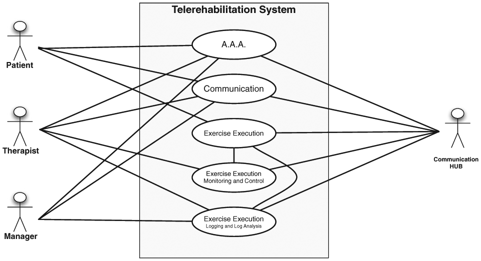
Telerehabilitation systems’ main services.
It is worth noting that the services presented above do not include maintenance services that involve a Manager, the Communication HUB and the Patient and/or the Therapist subsystems. These services enable a system manager to interact with the subsystems and, for instance, to change the configuration parameters of the local control in the Patient subsystem. These services will not be discussed in the following. Conversely, in the following, first we focus on the implementation of the proposed architecture combined with the CBM-Motus rehabilitation robot, including the Communication, the Exercise Execution and the Exercise Execution, Monitoring and Control services.
Implementation of subsystems
The general scheme for robot-aided telerehabilitation, previously presented in Figures 1 and 2, has been tailored to use the CBM-Motus robotic device. In particular, we used the Qt (https://www.qt.io) library to implement user interfaces (UIs), standard C libraries to manage transmission control protocol (TCP)/IP communications among subsystems and Aerotech libraries for the control of CBM-Motus motors. The libraries and the software have been tailored to run on cheap hardware settings and, indeed, all the systems developed in this work run seamlessly on Pentium 4 workstation equipped with less than 1 GB main memory.
Each subsystem presented in the previous subsection has been implemented as a software component. Hence, our telerehabilitation system based on the CBM-Motus robot is composed of Patient, Therapist, Manager and Communication HUB software components. The architecture of each software component is outlined hereafter.
Patient software component
The architecture of the patient software component is presented in Figure 3. Such a component implements the following functionalities:
It controls the robotic system;
It implements the UI for the patient;
It implements the data communication logic for patient/therapist interaction.
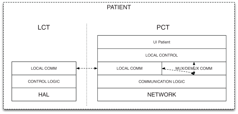
Patient component architecture.
The architecture of the software component is composed of two tiers: (1) the Local Control Tier (LCT) that controls the robotic rehabilitation end-point and (2) the Patient Control Tier (PCT) that manages the UI, the interaction with the first tier and the remote exchange of data.
The LCT is a multilayer software component for the direct control of the robotic system. The lowest layer abstracts the hardware and implements a general software interface (HAL – hardware abstraction layer); the second layer implements local and time-critical control functionalities for the robot management (Control logic), and the highest layer (Local comm.) provides a communication interface based on standard inter-process communication (IPC), to exchange messages (commands and data) with the other tier.
The PCT is a multilayer software component that implements rehabilitation exercises (Local control), the User Interface for the patient (UI Patient) and communication functionalities (Communication Logic and Local Communication). Local communication functionalities are based on standard IPC, whereas the interaction with other rehabilitation systems, mediated by the Communication HUB, is based on the TCP/IP network protocol.
Therapist software component
The Therapist software component architecture is shown in Figure 4. It implements the following functionalities:
It allows the therapist to monitor the execution of the patient’s exercises;
It allows the therapist to change exercise parameters online.

Therapist component architecture.
The architecture of the software component is composed of multiple layers. From bottom to top, the Network layer provides communication functionalities and, in particular, it is based on the TCP/IP protocol. The Communication Logic manages uplink (data) and downlink (control messages) flows, whereas the Remote Control layer maps therapist actions to commands for the patient software components. Eventually, the UI Therapist implements the graphical interface that the therapist uses to monitor and issue commands. Data messages to the therapist UI are sent by means of TCP packets at the same rate they are generated for the patient UI.
Manager software component
In the current implementation, the Manager software component allows monitoring the execution of exercises concurrently with the therapist. The architecture of the Manager software component, shown in Figure 5, is hence the same presented for the Therapist. Contrary to the Therapist, the Manager cannot issue control operation during exercises, but it is enabled to monitor exercises and command flows. Moreover, the manager manages hardware settings that are out of the scope of therapist’s actions.

Manager component architecture.
Communication HUB software component
The architecture of the Communication HUB software component is shown in Figure 6. Such a component provides the following functionalities:
It manages the authentication of users;
It manages communications among other software components;
It implements a local debug console for system monitoring.

Communication HUB architecture.
To implement these functionalities, the Communication HUB relies on a three-layer architecture. The Network and the Communication Logic layers implement a TCP/IP service to which all the other software components (Patient, Therapist and Manager) can connect. The Auth Logic sublayer controls if a given software component is allowed to connect and which role it has. The Hub Logic sublayer dispatches messages (data and commands) among the connected subsystems.
The CBM-Motus
The CBM-Motus is a planar end-effector machine for upper limb rehabilitation (Figure 7) conceived to address the following main requirements: low and isotropic inertia, simplicity in the mechanical structure, lightness and compactness in order to enable portability and low cost to favour home usage. 34 It has a Cartesian kinematic structure consisting of two modules connected by a double prismatic joint each corresponding to an actuated axis (i.e. x and y axes). Each module includes six pulleys with the same radius (25 mm) and two belts.35,36 The double prismatic joint ensures that only stretching (tensile) forces are transmitted to the belts. In this fashion, only the component of the force that is orthogonal to the same bar can be transmitted to each bar; consequently, the bar stretches the belts but it does not bend them. 35 The total mass of the robot (frame and motors included) is less than 30 kg. Further details on robot design and functionalities can be found in the work by Zollo et al. 34

Overview of CBM-Motus.
The robot control belongs to the category of assist-as-needed control paradigm;37,38 hence, it aims at providing the patient with the minimum level of assistance needed to accomplish the task, by monitoring the patient’s status by means of performance indicators. Therefore, an impedance control with adjustable parameters has been implemented. It can be written as follows

with

In equation (1),
The control is tailored to the subject’s motion abilities by updating stiffness matrix
The two control parameters (i.e.


They are weighted sums of a few of the aforementioned performance indicators where
A threshold strategy is then applied to set the value of control parameters. This takes into account that equations (3) and (4) continuously vary in the interval

where
The global system is shown in Figure 8. The scheme shows the main blocks involved in the integration of the CBM-Motus and the proposed architecture. Low latency controls are implemented in the LCT, while exercise-wide parameters (e.g. the activation of the feedback forces) are managed by the PCT. The PCT performs the update of exercise parameters directly or under the control of the Therapist. The exchange of data is mediated by the Communication HUB. The granularity of viable control depends on the latency and the bandwidth exhibited by the Patient-to-Therapist and Therapist-to-Patient communication channels.
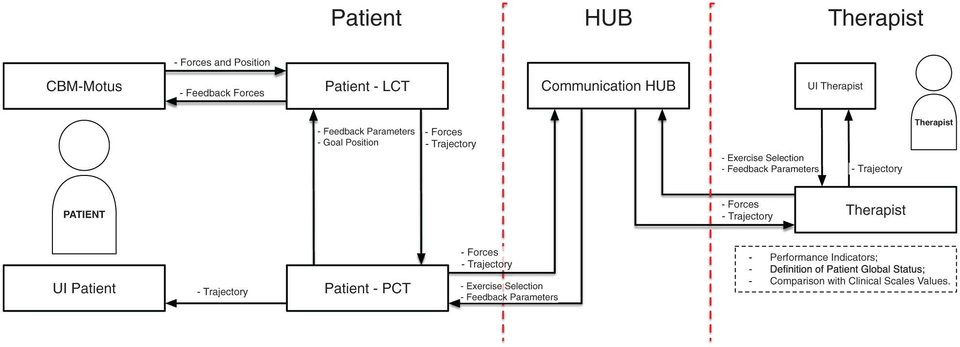
The modular architecture for telerehabilitation applied to the CBM-Motus rehabilitation robot. The patient side includes the robot and the patient–robot interaction modules; the therapist side includes evaluation and therapy modules, allowing therapy definition based on the evaluation of the patient, thanks to quantitative performance indicators and clinical scales.
Experimental trials
The patient-alone configuration of the Patient subsystem has been thoroughly evaluated. Seven healthy subjects have been asked to perform typical upper limb robotic exercises, for example, clock-game.8,10 Each session consists of 160 point-to-point movements in 8 different directions rotated at 45°. They are grouped into 80 trials performed without assistance, in order to measure subject performance and update control parameters, and 80 trials performed with a level of assistance tailored to the patient status (described through the computed performance indicators).39,40 The session of 160 point-to-point movements has been repeated under two different conditions, that are, (1) healthy behaviour and (2) simulated post-stroke behaviour.
In order to make the results comparable among the subjects and ensure repeatability of the performed trials, the simulated post-stroke behaviour was implemented by applying a constraint on the healthy subjects. It consists of an elastic sling applied on the subject’s arm between the forearm (12 cm below the elbow joint) of the ipsilateral arm and the axilla of the contralateral arm.
The resulting elastic force was not exactly quantified due to the unknown elastic constant of the sling. However, it is assumed to be in the range [15, 30] N. The proposed constraint intends to increase the difficulty of elbow flexion/extension movements, which are the most affected movements after a stroke event.
Moreover, elastic force of the band strictly depends on its length and the length of user arm. No adjustments regarding arm-length or subject-based strength have been performed; such an aspect might have introduced an appropriate amount of uncertainty.
Hence, subjects were asked to perform 80 point-to-point movements without robot assistance (
The performance indicators have a twofold purpose: (1) evaluation of the therapy progress; (2) adaptation of the level of assistance to the patient condition, by updating control parameters through equations (3) and (4). Afterwards, control parameters
Limits of the proposed architecture in Internet scenarios were investigated by means of modelling. Real data obtained from tests were used to fill the model and characterize the system. In particular, we focused on the assessment of the Patient-Therapist-Patient control loop. The aim was to quantify the level of control that can be applied under realistic communication constraints. We measured the computation time required to calculate performance indicators in the following three different conditions:
For the single point-to-point movement;
For a block of 16 movements (i.e. one repetition of the whole clock-game);
For a block of 80 movements (i.e. five repetitions of the clock-game).
Furthermore, we extracted the time required for transmitting data and commands between the Patient and Therapist. These times can be used to compute closed-loop communication delays and characterize applicable control strategies. In particular, a single control loop requires the following:
The generation of patient’s data:
The full transmission of such data to the Communication HUB:
Reception and decoding of the patient’s data:
The full forwarding of data to the therapist:
The computation of performance indicators and updated parameters:
The full transmission of updated parameters to the Communication HUB:
Reception and decoding of the therapist’s data:
The full forwarding of data to the patient:
The application of new parameters:
Assuming that (1)

This time has to be lower than the maximum waiting time that the patient can accept during exercise phases involved in parameters update.
Results and discussion
In this section, results obtained from the experimental validation of the proposed telerehabilitation architecture are reported. First, the results of the assist-as-needed exercises performed with the CBM-Motus are shown and then the results of the communication tests between patient and therapy sides are reported.
As regards the experimental trials carried out with the CBM-Motus, hand trajectories and velocities in the Cartesian space of one subject are shown for unassisted healthy, unassisted simulated post-stroke condition and assisted simulated post-stroke behaviour (Figures 9–11). As expected, after adaptation of control parameters, simulated post-stroke behaviour tends to the healthy one in terms of trajectories as well as of velocity and smoothness. Moreover, since post-stroke subjects typically have higher motion difficulty in directions requiring elbow extension, it has been chosen to show NW (NorthWest) hand velocity trajectories to highlight performance improvement after control parameters update.
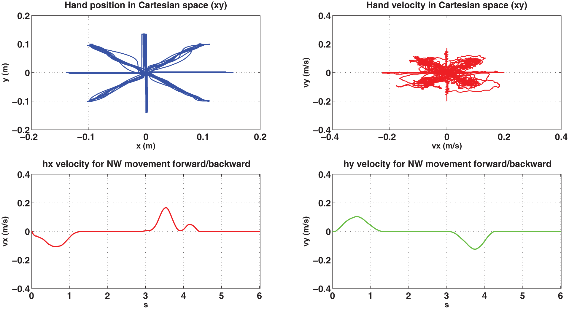
Subject 1 performing 80 repetitions of the clock-game in healthy condition: Cartesian position (upper left side), Cartesian velocity (right upper side), x component of hand velocity over time during NW forward/backward movement (lower left side) and y component of hand velocity over time during NW forward/backward movement (lower right side).
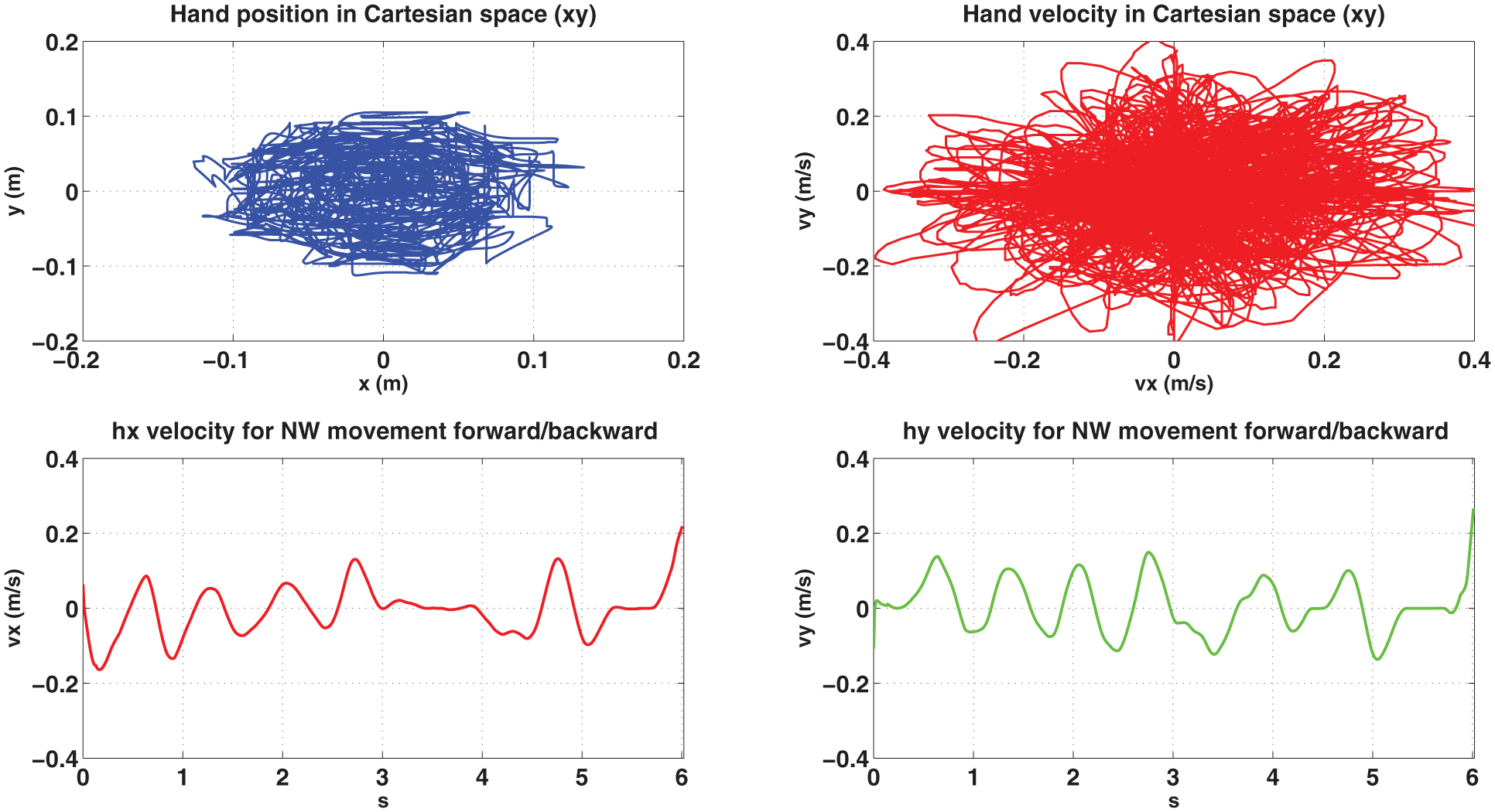
Subject 1 performing 80 repetitions of the clock-game in unassisted simulated post-stroke condition: Cartesian position (upper left side), Cartesian velocity (right upper side), x component of hand velocity over time during NW forward/backward movement (lower left side) and y component of hand velocity over time during NW forward/backward movement (lower right side).

Subject 1 performing 80 repetitions of the clock-game in assisted simulated post-stroke condition: Cartesian position (upper left side), Cartesian velocity (right upper side), x component of hand velocity over time during NW forward/backward movement (lower left side) and y component of hand velocity over time during NW forward/backward movement (lower right side).
In Figure 12, a bar plot of the selected performance indicators is shown for both unassisted and assisted movements taking into account mean values and standard deviation. Even though no clinical considerations can be extracted from these data, the indicator trend confirms the expected improvements between unassisted and assisted tasks, especially observing the simulated post-stroke behaviour. Moreover, it shows the efficacy of the control modulated by the therapist side and the functioning of the proposed telerehabilitation architecture.

Mean values and standard deviations of performance indicators for all the subjects before and after updating control parameters. They are reported both for healthy (left) and simulated post-stroke condition (right).
The characterization of the Patient-Communication HUB-Therapist control loop is based on data reported in Table 1. The table presents mean and standard deviations of computation times required to update control parameters, and the size of data transferred between the patient and the therapist in order to perform this computation and to apply results back into the Patient subsystem. In particular, we extracted these data considering an update operating between the following three groups of elementary actions: (1) the single movement scenario, (2) the 16 movements scenario and (3) 80 movements scenario. Based on these data, we can compute an upper bound of the closed-loop time for parameters update as

where we used equation (5) assuming that each direct data exchange is composed of two components:
Architecture validation: computational time for updating control parameters (mean and standard deviation (SD)) and file size of the information exchanged throughout the architecture blocks.

SD: standard deviation.
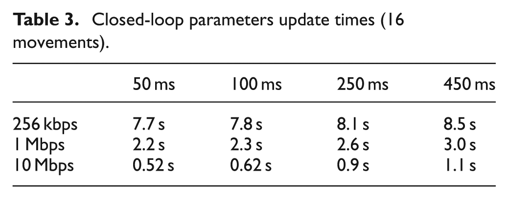
Tables 2–4 present values of the time required for the closed-loop update of parameters in the case of the configurations of Table 1 and considering different values of
Closed-loop parameters update times (single movement).

Closed-loop parameters update times (16 movements).
Closed-loop parameters update times (80 movements).
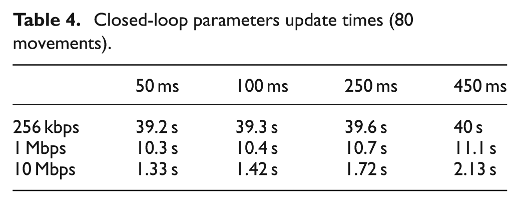
When the amount of data communicated between systems increases, the results change and the most critical parameter is the transmission rate. If we assume that the maximum waiting time acceptable between 16 movements (80 movements) is 2 s (20 s), all the configurations having a communication rate equal to 10 Mbps (1 or 10 Mbps) are valid, independent of the
Results demonstrate the feasibility and limits of the proposed architecture for upper limb robotic telerehabilitation. The implemented system is able to send data and compute performance indicators in a safe and reliable way. In this condition, the subject who is performing the robot-aided exercise has enough time to accomplish the required task being involved also by means of visual feedback.
Being a preliminary phase, the computation of performance indicators has been executed in an offline modality and therefore communication stability has been proved by the aforementioned tests. Obvious extension of the proposed architecture will be the computation of the performance indicators and the update of control parameters in a real-time environment. This will allow the therapist to monitor and evaluate the therapy in a simultaneous way by setting the type of exercise, the level of difficulty and the needed robot assistance depending on the specific patient’s condition.
Conclusion
This article has presented a novel modular architecture for telerehabilitation. The architecture has been conceived to be as general as possible in order to be adapted to different telerehabilitation scenarios, including or not including the robot. The modular architecture has been applied to the CBM-Motus, a planar robot for upper limb rehabilitation previously developed by the authors, controlled through an assist-as-needed control. The experimental validation on healthy subjects simulating a post-stroke behaviour has demonstrated the functioning and reliability of the novel architecture, as well as the modularity of the proposed system able to be tailored to different unilateral robot systems. Tests performed with the CBM-Motus encourage the potential use of the implemented system in a clinical scenario. To this purpose, future studies on post-stroke subjects’ in-home telerehabilitation programmes will be taken into account in order to enhance patients’ independence and encourage faster recovery from stroke.
Footnotes
Academic Editor: Nicolas Garcia-Aracil
Declaration of conflicting interests
The author(s) declared no potential conflicts of interest with respect to the research, authorship, and/or publication of this article.
Funding
The author(s) disclosed receipt of the following financial support for the research, authorship, and/or publication of this article: This work was supported by the National Project Industria 2015 – DAHMS (Distributed Architecture Home Modular Multifunctional Systems), CUP B85E10003020008 and by European Project H2020/AIDE: Multimodal and Natural Computer Interaction Adaptive Multimodal Interfaces to Assist Disabled People in Daily Activities, CUP J42I15000030006.