
Abstract
Recently, the preservation and survey of cultural heritage goods is attracting increasing interest from the media. Several famous historical sites seem to require an increased effort to maintain their preservation. Nevertheless, it is very difficult to find sufficient funds and human resources to fulfil these needs. Accordingly, this paper outlines a specific application of service robotics to cultural heritage, with the aim to reduce the required time and costs for surveying and maintaining cultural heritage goods. These applications require careful attention paid to the proper design of a robotic mobile platform with the features necessary to fulfil tasks of architectonic survey and preservation. To this end, specific operation scenarios have been carefully described in order to identify the specific design requirements and constraints that are raised by, for example, the necessity of operation over delicate surfaces, or the presence of unevenness or obstacles. The authors then propose a design solution for a service robot fit for the analysis, survey and conservation of historical sites, as based on the characteristics of the outlined scenarios. A preliminary prototype is also described herewith, in order to show its engineering feasibility in relation to the simulated operation scenarios.
Introduction
Cultural heritage may be defined as “the entire corpus of material signs – either artistic or symbolic – handed on by the past to each culture and, therefore, to the whole of humankind” [1]. The term “cultural heritage” includes tangible culture, intangible culture and natural heritage [2], and encompasses several main categories [3]: movable cultural heritage (such as paintings, sculptures and manuscripts); immovable cultural heritage (such as monuments, buildings, archaeological sites, etc.); underwater cultural heritage (such as shipwrecks and underwater ruins); intangible cultural heritage (such as traditions and rituals); and natural heritage (such as landscapes, physical, biological or geological formations).
Recently, a number of research projects have attempted to develop mobile robotic platforms in the field of cultural heritage (for example, in museums [4–6]), with the aim to supply remote access to distant users, to allow people to be virtually guided around a museum, or to survey certain restricted areas. In terms of immovable cultural heritage, many references in the literature propose the use of mobile robots for environment-modelling tasks. In fact, mobile robots can be equipped with sensors, such as cameras and laser rangefinders, which can acquire and process various kinds of data while navigating around the environment, with minimum human interaction [7]. Despite the high number of proposed solutions, only a few authors (such as [8–10]) have explicitly suggested the use of service robots for field test applications in the domain of cultural heritage. Most of the proposed applications have focused their approach on wheeled solutions, which have well-known drawbacks in terms of mobility.
One new challenge in the field of architectonical survey involves approaches to the analysis and safeguarding of immovable cultural heritage, through the use of mobile robots performing complex tasks on various types of surface.
Hexapod robots can be suitable for survey operations, since they have the ability to overcome obstacles that are comparable with the size of their legs [11]. Hexapod walking robots also benefit from a low impact on the terrain and have great mobility in natural surroundings. This is especially important in applications where it is essential to keep the terrain largely undisturbed, such as the surveying of historical sites [12]. Hexapod robots can establish a static equilibrium easily while moving. In addition, they can move forward with many different kinds of gait, to adapt to different speeds and loads. Hexapod robot architecture can easily allow for the operation of a 3D scanning system. This innovative technology allows for the creation of virtual 3D models of large and complex objects with remarkable levels of definition. Despite the above-referenced aspects, many challenges remain to be tackled before hexapod walking robots can have a more widespread use. Some of their current open design issues include high complexity, high cost, low energy efficiency [13], and relatively low speed. Walking robots usually require a high number of specific skills in order to manage the many necessary actuators, sensors, transmissions and supporting hardware/software.
Service tasks in cultural heritage
Analysis and survey activity on immovable cultural heritage is generally carried out through manual operations with a few assisting devices. Usually, the activity consists of a series of related tasks, which can often be repetitive, to acquire data from the historic works, both in terms of dimensions and detailed figures [14]. Those repetitive tasks can be enhanced with the assistance of suitable robotic devices. In addition, a certain automation of current manual operations as part of the survey can help in the obtaining of more accurate results in a shorter time. Moreover, there are several cases and situations in which these measuring and figure acquisition activities cannot be performed by human operators, as, for example, in the case inaccessible sites, but also just in order to obtain an adequate resolution of results.
Typical on-field architectural survey activities can be recognized as including measuring the dimensions of the goods, detecting their general figures in term of shape and volume, acquiring images or videos to monitor both their general status and details, and inspecting the structure of the goods [15]. Most of these activities can be assisted with the use of robotic devices, by which they can be made even more successful, both in terms of productivity and quality of results, as well as by shortening the operation time. In most cases, the survey activity requires closing the historical goods to public visitation. The possibility of having assisting robotic devices that can operate within a short time, even without requiring large frames that might obscure the historical goods, is a strong demand. The main tasks inviting solutions using robots can be identified as:

Basic step for robotics application in survey activity
high-resolution image acquisition of surfaces, with the aim of a detailed graphical reconstruction and interpretation;
identification of details and their location within the plan of the structure in which they are located; representation and reconstruction of designs that appear on curved or hidden surfaces; acquisition of images with suitable static mechanisms that are not available with current photographic means, both due to light sources and camera location with respect to the orthogonality of structural surfaces; possible use of additional instrumentation, even within a single survey campaign/activity; possible use of the robot's abilities for additional evaluation and computation of structural characteristics.
According to [16], a general methodology for the application of robotic systems to surveying can be described as a sequence of steps, as shown in Fig. 1.
The above-mentioned considerations and concepts have been applied to the case study of the ancient Cosmatesque pavement at the Basilica of Montecassino. The Abbey of Montecassino was founded by St. Benedict in 529 C.E. and survived through a prestigious period in history. On 15 February 1944, the Abbey was completely destroyed; reconstruction started the following year and was officially completed in 1964 [17]. Fig. 2 shows the reconstruction plans of the abbey library at Montecassino. A first virtual simulation was conducted by assuming a possible access through an impervious interspace in the ancient medieval flooring of the Montecassino Cathedral [18]. The pavement's survey details and current status are unknown; the floor is now located under the current basilica pavement. Its positioning can be identified in the cross section (Fig. 2a) and planimetric view (Fig. 2b) of the abbey complex. Thus, given the lack of light and air, inspections and other operations concerning the Cosmatesque mosaic would be unsafe and unsuitable work for humans. For this reason, after the reconstruction of the new basilica, the floor was never inspected to analyse its state of health or to carry out stylistic analyses of its decoration. This case study demonstrates the impossibility of using human operators, and is therefore well-suited to experimentation with the application of robotics to this branch of the study and conservation of architectural heritage in general, and historical pavements in particular. Fig. 3 shows an example of a SolidWorks simulation of survey activity on the Cosmatesque floor.

a) Cross-section of the reconstruction design for Montecassino Abbey; b) Planimetric view (the blue area indicates the location of the ancient pavement)

A simulated example of the survey activity
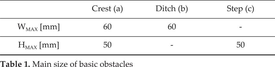
The first step of the process involves defining the requirements and operation characteristics that are suitable for an automation or improvement using robotic devices. Since the variety of irregular terrains is unlimited, it has been difficult to cover all the different cases of walking over irregular terrain. In order to study this problem, the underlying features have been schematized into basic geometric forms. Fig. 4 shows the geometric features and related parameters that have been considered: crest, ditch and vertical step. One survey activity carried out by DART laboratory estimated the operating scenario to be a flat surface with max 1% slope, 1 cm unevenness, and a resolution of survey equal to or lower than 0.5 cm. The size of the overall surface to be surveyed is assumed to be about 20 m2. Table 1 shows the main size of the basic obstacles in Fig. 4. The above numbers have been validated by referring to a study on the Cosmatesque pavements at Montecassino Abbey [19].

Basic obstacle for robotics application in survey a) crest b) ditch c) vertical step
The second step concerns the development of the survey methodologies. The design of the survey activity has been carried out through simulations and experiences, in order to define the analytical procedures and to conceive operational strategies for the systems and their use within the survey activity. Attention has been paid to operational features, in terms of user-oriented facilities and human-machine interfaces that can determine successful user-oriented results for survey operators.
Main size of basic obstacles
In the third step, the design process is focused on system architectures that are able to perform the required survey strategies. Design algorithms have therefore been formulated for the design of these robotic systems, by approaching the problems of structure type, dimensional synthesis, mechanical design of parts, and endowment of suitable internal and external instrumentation. A SolidWorks environment has been used, due to the convenience of its features for structure analysis and the operational study of multi-body systems, in order to check the feasibility of a real prototype. Simulations have been used for investigating basic robot performances in order to check the design feasibility before prototyping.
The fourth step deals with the methodology for survey operations using a robotic system. SolidWorks simulations have been carried out in order to validate the proposed operation strategies. In this elaboration process, significant effort has been put into the activity of analysing and simulating proposed solutions and operations. These simulations can be summarized as follows: the robot's primary characteristic is its capacity to move within the area under examination and to carry image-capturing equipment in order to perform the first analyses of the object. Attention has mainly been focused on walking gaits and basic operations such as climbing steps, and overcoming crests and ditches. At the same time, since the surfaces in historical sites are extremely irregular, in addition to performing forward motion, the robot must also ensure that the image-capturing equipment remains parallel to the floor.
To begin testing the suitability of the elements proposed, these operations were verified with SolidWorks simulations that provide virtual 3D models, allowing a reduction in time and costs in the planning phase. The SolidWorks environment allows for the thorough evaluation and testing of a model from the initial design stages, while also simulating the environment in which the robot will work.
In the fifth design step, the results of the previous step were applied to the construction of a prototype. In the final step, results were validated using tests carried out with the prototype in laboratory experiences and finally in preliminary tests of survey activity.
The Cassino Hexapod III was developed at the LARM and DART laboratories with the aim of designing a walking robot for the surveying, analysis and conservation of historical sites. The main characteristics of the robotic system can be outlined in terms of a mobile platform carrying several instruments, which include image-capturing instruments (in terms of photos and videos), thermal-inspection instruments, laser scanners, and other sensors for distance and orientation measurements. Thus, a certain volume and payload will need to be available on board the robotic system. Careful motion is expected from the robotic system, in order to ensure optimal image capturing of the surface and its environment, and to avoid damage to the terrain itself or other components of the environment under exploration.
Other characteristics of the proposed robot were selected by considering previous experiments at LARM, and can be summarized as follows:
low-cost, both in design and operation (< 1000 Euros); user-friendly operation, including for non-expert users; wireless operation in environments that cannot be reached by, or are unsafe for, human operators; operating speed on regular terrain of > 0.1 m/s; operating speed on uneven terrain of > 0.05 m/s.
After considering the above-mentioned conditions and constraints, it was thought necessary to design a multileg-ged robot with a suitably large body and powered wheeled feet. Further details of the analysis of design requirements of the Cassino Hexapod III can be found in [20]. In particular, reference [20] reports the Cassino hexapod design procedure in detail, starting from the identification of the design requirements and constraints. The specifically identified design requirements and constraints were then used for identifying the most convenient architecture among the many possible choices. A structure with six legs was chosen in order to ensure contact of at least three feet with the ground at all times, so that a plane can be easily determined by the robot body. Powered wheeled feet were installed on the legs in order to afford the possibility of smoothing and regulating the contact force during the robot's walking motion. This choice is useful in order to prevent damage to the pavement surface and to improve stability. An axi-symmetrical configuration with a rectangular shape was adopted. The overall robot configuration is presented in Fig. 5 [21]. The robot can fit into a cube of 0.4m × 0.3m × 0.3m. The main body, made in Delrin, can carry on-board control cards, sensors and a battery. Overall, the robot weighs about 30N. Kinematic configuration is based on relatively few components with a fairly simple mechanical design, which consists of two links connected through a knee joint. This assembly solution was designed based on previous experiences that are reported in [22].

A Solid Works model of the Cassino Hexapod III
The proposed robotic leg has the function of positioning the wheel in proper contact with the ground. Its specific architecture can be assimilated to a 2R robotic arm. Considering the peculiarities of the proposed architecture and its operation, a 1mm accuracy can be considered suitable. Each of the legs has three DoFs: two of these have a movement with a range of between −90° and 90°, that allows the robot to pass over obstacles and to walk without moving its wheels. The third motor allows the wheels to move in a full rotational range. An exploded view of the leg is shown in Fig. 6a) to make the assembly scheme clear. The leg measures 160mm in length, 45mm in width and 20mm in depth. Its total weight is about 2.5 N. The diameter of the omni-wheels is 60mm. They allow the robots to be steered in a wheeled operation. Fig. 6b) shows a simulated detail of the obstacle avoidance capability of a single leg. The proposed design allows it to pass over a step of 80mm. The robotic arm shown in Fig. 5 is attached above the robot's main body and allows it to manipulate objects [23] and perform 3D laser scanner operations.
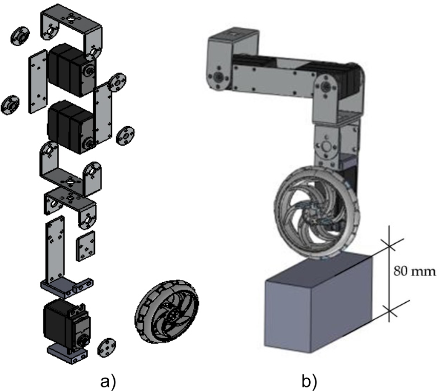
Robotic leg: a) exploded view, b) Solid Works simulation of its obstacle avoidance capability
The Cassino Hexapod III is powered by 18 servomotors, 12 of which are digital servos (Model DS RDS3115MG) that give mobility to legs, while the other six actuators are continuous rotation servos (Model DS AS3103PG), used for wheeled operation. A commercial low-cost control board (Arduino Mega 2560) was adopted as the control unit. A customized software has been developed to allow the walking gaits and wheeled operation of the hexapod. A wireless communication link allows the exchange of information between the robot and a remote controller.
Fig. 7 shows a schematic view of the control and sensor architecture, and Fig. 8 shows an assembly detail. A remote Wi-Fi interface has been achieved by means of an Arduino Yun control card. The degree of autonomy of the path-planning layer includes active human-robot interaction. A high level of remote control can be established using a PC or smart device that can send a task plan to the robot using the Wi-Fi network. At this stage, obstacles and ditches are detected by means of the camera feedback. The pattern switching is done through the user interface. However, additional sensors can be included to increase the degree of operation autonomy. The prototype has been equipped with an LPMS-B OEM sensor, a wireless inertial measurement unit [24–25]. The unit can measure orientation about all three global axes. The IMU sensory feedback can be used for remote robot levelling, as shown in Fig. 9.

Control and sensor architecture scheme for the Cassino Hexapod III: a) Arduino Yun card, b) Arduino Mega 2560 card, c) servo shield, d) voltage regulator, e) IMU sensor, f) Wi-Fi camera, g) 3D laser scanner, h) servomotors, i) PC, 1) smartphone

A detail from the assembled control architecture: a) LiPo battery, b) Arduino Yun control card, c) LPMS-B OEM sensor, d) Arduino Mega 2560 and servo interface

An example of IMU sensor feedback [27]
A commercial Wi-Fi camera with a high resolution has been attached to the robot's main body in order to provide environment feedback, and to acquire images and videos. A suitable light source can be conveniently obtained by means of high-power LEDs that will have a limited power consumption. Further details of sensors and actuators can be found in [26]. The kinematics and dynamics of the Cassino Hexapod are presented in [27–28–29]. A LiPo battery (7.4V, 2600mAh) provides the power supply to the control cards and actuators. The payload of the hexapod is 1kg. Fig. 10 shows the built prototype of the Cassino Hexapod III, while Fig. 11 shows the prototype of the robotic arm for laser-scanner operations.
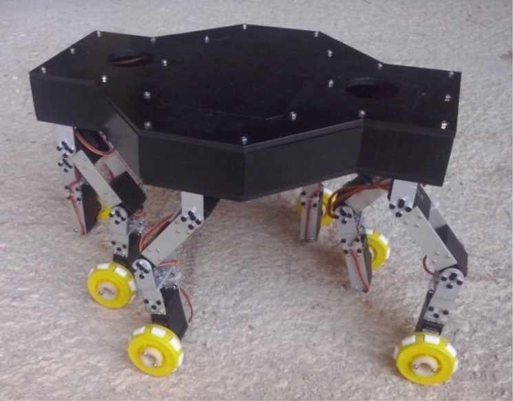
A built prototype for the Cassino Hexapod III

The built robot arm for laser-scanner operations
The operation of the servomotors was achieved by developing an appropriate software on the Arduino Mega control board, as well as by using the Arduino Servo library. In particular, the Arduino Servo library provides features for a user-friendly operation of standard servomotors and continuous rotation servos. Fig. 12 shows the correlation between the control signal and the output shaft position for a digital servomotor. Further details on servo operation can be found in [26].

Control signal for joint servo operation
Walking with a tripod gait was simulated in virtual environments. Fig. 13 illustrates a tripod gait, in particular showing frames of the main steps in a simulated walking strategy with the related qualitative cyclogram. Tripod gait is a regular, periodic gait, where the front and back legs on one side lift at the same time as the contralateral middle leg, forming alternating tripods. In Figs. 13 and 14, ϑ1 is the hip joint and ϑ2 the knee joint. For each tripod, the legs are lifted, lowered, and moved forwards and backwards at the same time. Tripod gait is suitable for relatively high-speed walking over relatively flat ground. Further details of path planning for the Cassino Hexapod III can be found in [29].

Walking strategy a) SolidWorks simulations of a tripod gait b) qualitative cyclogram for the legs
In order to study a step-climbing strategy, we here define the two legs closest to the step as the “front legs”. The second two legs are defined as the “mid legs” and the third two legs are the “back legs”. It is assumed that the robot is initially near the step. The flow for climbing a high step is as follows: in Fig. 14a) the robot raises its front legs sideways to match the height of the step. The robot supports its body with its mid and back legs, and moves forward as much as possible without hitting the step (Fig. 14b). Then, in Fig. 14c), the robot puts its front legs over the step and raises its middle legs backwards to match the height of the step; the robot then supports its body with its front and back legs, moves forward as much as possible, and puts its mid legs on the step. Fig. 14d) shows the robot raising its back legs backwards to match the height of the step. Then the robot puts its back legs on the step and move forward with all its legs. Fig. 14e) shows the qualitative cyclogram for the robot legs.

Step climbing strategy; a-d) SolidWorks simulations, e) qualitative cyclogram for the legs
In order to study a ditch-overcoming strategy, we must define the max operation sizes by referring to a terrain depression of which the robot leg cannot touch the bottom and which it cannot step across (Fig. 15). A SolidWorks simulation allow to find the max operation depth, which is H= 80mm, and the max operation width, which is W= 85mm [30].

Max operation sizes in a ditch-overcoming strategy
Fig. 16 shows several frames that have been collected during a tripod gait operation involving the Cassino Hexapod III, similar to the simulation that was shown in Fig. 13. Specifically, Fig. 16a) shows the first tripod step, as depicted in Fig. 13, while Fig. 16b) shows the next set of frames concerning the second tripod set.

Main steps in a walking strategy: a) first tripod, b) second tripod
Fig. 17 shows frames taken from an experimental test involving step-climbing. Specifically, Fig. 17a) shows the robot raising its front leg sideways to match the height of the step; Fig. 17b) shows the robot raising its other front leg and placing it onto the step; Fig. 17c) shows the robot moving forward as much as possible in wheeled mode; in Fig. 17d), the robot is raising its middle legs backwards to match the height of the step, moving its body forward using its wheels, and then placing its middle legs onto the step; and in Fig. 17e), the robot is moving forward using its wheels, before raising its back legs and placing them onto the step. Finally, the robot is able to support its body using all its legs and it moves forward. Fig. 18 shows frames that have been taken during a crest-overcoming test. Specifically, Fig. 18a) shows the robot as it approaches the crest; Fig. 18b) shows the robot raising its front leg sideways to match the height of the crest, and then moving forward using its wheels; Fig. 18c) shows the robot that placing its front leg on the ground; Fig. 18d) shows the robot raising its other front leg backwards to match the height of the crest; and Fig. 18e) shows the robot leaning its front legs on the ground and thereby overcoming the crest.

Main steps in a step-climbing strategy: a) first step, b) second step, c) third step, d) fourth step, e) fifth step

Main steps in a crest-climbing strategy: a) first step, b) second step, c) third step, d) fourth step, e) fifth step
Fig. 19 shows frames that have been taken during a ditch-overcoming test. Specifically, Fig. 19a) shows the robot approaching the ditch; Fig. 19b) shows the robot raising its front leg sideways to overcome the ditch and then moving forward as much as possible using its wheels; Fig. 19c) shows the robot placing its front leg on the other side of the ditch; Fig. 19d) shows the robot raising its other front leg; and Fig. 19e) shows the robot leaning both its front legs on the other side and thereby overcoming the ditch.

Main steps in a ditch-overcoming strategy: a) first step, b) second step, c) third step, d) fourth step, e) fifth step
The authors have proposed a novel application for service robotics, in surveying and maintaining cultural heritage goods. This specific application has been investigated with reference to a case study at Montecassino Abbey, Cassino, Italy. The main features of the proposed application were outlined in relation to a specific scenario, in order to identify the specific design requirements and constraints. Then, a design solution was proposed such as a novel robotic hexapod walking platform. Simulation tests were carried out under various operation conditions, aiming to verify the feasibility of the proposed design solution for the proposed tasks. A prototype was built and preliminary tests were reported in order to show the main characteristics and operation features of the built robotic platform within a typical cultural heritage-like environment.